EP1028449A1 - Röntgenröhre - Google Patents
Röntgenröhre Download PDFInfo
- Publication number
- EP1028449A1 EP1028449A1 EP00200428A EP00200428A EP1028449A1 EP 1028449 A1 EP1028449 A1 EP 1028449A1 EP 00200428 A EP00200428 A EP 00200428A EP 00200428 A EP00200428 A EP 00200428A EP 1028449 A1 EP1028449 A1 EP 1028449A1
- Authority
- EP
- European Patent Office
- Prior art keywords
- ray tube
- tube according
- electron beam
- anode
- ray
- Prior art date
- Legal status (The legal status is an assumption and is not a legal conclusion. Google has not performed a legal analysis and makes no representation as to the accuracy of the status listed.)
- Granted
Links
- 239000000463 material Substances 0.000 claims abstract description 5
- QSHDDOUJBYECFT-UHFFFAOYSA-N mercury Chemical compound [Hg] QSHDDOUJBYECFT-UHFFFAOYSA-N 0.000 claims abstract description 5
- 230000005855 radiation Effects 0.000 claims abstract description 5
- 229910001385 heavy metal Inorganic materials 0.000 claims abstract description 4
- 238000010894 electron beam technology Methods 0.000 claims description 9
- 239000010432 diamond Substances 0.000 claims description 7
- 229910003460 diamond Inorganic materials 0.000 claims description 7
- BASFCYQUMIYNBI-UHFFFAOYSA-N platinum Chemical compound [Pt] BASFCYQUMIYNBI-UHFFFAOYSA-N 0.000 claims description 4
- 229910052753 mercury Inorganic materials 0.000 claims description 3
- 229910052751 metal Inorganic materials 0.000 claims description 3
- 239000002184 metal Substances 0.000 claims description 3
- RTAQQCXQSZGOHL-UHFFFAOYSA-N Titanium Chemical compound [Ti] RTAQQCXQSZGOHL-UHFFFAOYSA-N 0.000 claims description 2
- 229910052697 platinum Inorganic materials 0.000 claims description 2
- 229910052719 titanium Inorganic materials 0.000 claims description 2
- 239000010936 titanium Substances 0.000 claims description 2
- VYPSYNLAJGMNEJ-UHFFFAOYSA-N Silicium dioxide Chemical compound O=[Si]=O VYPSYNLAJGMNEJ-UHFFFAOYSA-N 0.000 claims 1
- 239000013077 target material Substances 0.000 abstract description 2
- 238000001816 cooling Methods 0.000 description 5
- 239000010405 anode material Substances 0.000 description 3
- 230000007423 decrease Effects 0.000 description 2
- 230000005684 electric field Effects 0.000 description 2
- 238000002844 melting Methods 0.000 description 2
- 230000008018 melting Effects 0.000 description 2
- OKTJSMMVPCPJKN-UHFFFAOYSA-N Carbon Chemical compound [C] OKTJSMMVPCPJKN-UHFFFAOYSA-N 0.000 description 1
- 229910052799 carbon Inorganic materials 0.000 description 1
- 238000006243 chemical reaction Methods 0.000 description 1
- 239000011248 coating agent Substances 0.000 description 1
- 238000000576 coating method Methods 0.000 description 1
- 239000012141 concentrate Substances 0.000 description 1
- 239000002826 coolant Substances 0.000 description 1
- 230000006378 damage Effects 0.000 description 1
- 230000000694 effects Effects 0.000 description 1
- 238000010438 heat treatment Methods 0.000 description 1
- 239000007788 liquid Substances 0.000 description 1
- 229910052756 noble gas Inorganic materials 0.000 description 1
- XLYOFNOQVPJJNP-UHFFFAOYSA-N water Substances O XLYOFNOQVPJJNP-UHFFFAOYSA-N 0.000 description 1
- 229910052724 xenon Inorganic materials 0.000 description 1
- FHNFHKCVQCLJFQ-UHFFFAOYSA-N xenon atom Chemical compound [Xe] FHNFHKCVQCLJFQ-UHFFFAOYSA-N 0.000 description 1
Images
Classifications
-
- H—ELECTRICITY
- H01—ELECTRIC ELEMENTS
- H01J—ELECTRIC DISCHARGE TUBES OR DISCHARGE LAMPS
- H01J35/00—X-ray tubes
- H01J35/02—Details
- H01J35/04—Electrodes ; Mutual position thereof; Constructional adaptations therefor
- H01J35/08—Anodes; Anti cathodes
- H01J35/112—Non-rotating anodes
-
- H—ELECTRICITY
- H01—ELECTRIC ELEMENTS
- H01J—ELECTRIC DISCHARGE TUBES OR DISCHARGE LAMPS
- H01J35/00—X-ray tubes
- H01J35/02—Details
- H01J35/14—Arrangements for concentrating, focusing, or directing the cathode ray
- H01J35/153—Spot position control
-
- H—ELECTRICITY
- H01—ELECTRIC ELEMENTS
- H01J—ELECTRIC DISCHARGE TUBES OR DISCHARGE LAMPS
- H01J2235/00—X-ray tubes
- H01J2235/08—Targets (anodes) and X-ray converters
- H01J2235/081—Target material
- H01J2235/082—Fluids, e.g. liquids, gases
Definitions
- the invention relates to an X-ray tube with a device for generating and Focusing an electron beam on a target.
- An X-ray tube of this type is known for example from DE 195 44 203.
- An electron source cathode
- An electron source cathode
- the electron beam is through this Arrangement with a very small focus and a relatively high electron density the target is directed so that X-rays are generated with high efficiency.
- the thermal conductivity of the anode decreases with increasing temperature. This in turn causes heat conduction from the electron focus in and through the anode material becomes lower and the temperature at the focal point continues increases so that the melting temperature of the anode material reaches even faster and can be exceeded. Destruction of the anode surface is then the immediate one Episode. For these reasons, it must be ensured that the focus temperature in X-ray tubes of this type does not exceed about 1500 ° C, so that in essence Dimensions without the possible further increase in the x-ray density must become.
- This measure can raise the focus temperature to approximately 2200 ° C without damaging the anode. Because the one emitted by thermal emission Energy is proportional to the fourth power of the anode surface temperature such rotating anode tubes operate essentially with radiation cooling. However, the measures mentioned are either relatively complex or only of limited effect.
- the invention is therefore based on the object of an X-ray tube of the type mentioned To create a way that produces a much higher X-ray density can be.
- This object is achieved according to claim 1 in such an X-ray tube by that the target is gaseous or vaporous at least in the operating state of the X-ray tube Contains material that is under pressure in one for electron and x-rays at least partially permeable chamber is included.
- the electron density at the focal point of the electron beam can be increased significantly, so that a much higher X-ray density can be achieved without the anode temperature takes impermissibly high values.
- a noble gas with a sufficiently high atomic number could be used as the material in the chamber be present, e.g. Xenon, both in the operating state and in the Breaks are gaseous.
- claim 2 describes the use of a Heavy metal that solidifies during the breaks (i.e. at around room temperature) can be liquid, and that in the operating state (i.e. at comparatively high temperatures) is in a vapor-like physical state.
- An advantageous embodiment is specified in claim 3.
- the entry window according to claim 4 and in particular according to its dimensioning Claim 5 has the advantage that on the one hand the passing electrons lose energy suffer from only about five percent, and that, on the other hand, the window pressure differences can withstand up to 100 bar.
- a coating of the entrance window according to claim 6 or 7 has the advantage that it even in the event of an unintentional increase in the operating pressure within the Chamber is not attacked and clouded by the high temperature plasma.
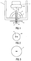
- an X-ray tube 1 has a cathode 2 and an anode 3.
- the cathode essentially comprises a cathode head 20 with a filament 21 (FIG. 2), by a power supply device (not shown) with a corresponding one Heating current is applied.
- the anode 3 opposite the cathode 2 is essentially semicircular, so that between the cathode 2 and the anode 3 a radial electric field is generated.
- a channel 4 with an inlet opening 41 for the electrons runs through the anode 3, which is opposite the cathode 2.
- the channel 4 is on with its outlet opening 42 Diamond window 7 directed a chamber 6, which contains the target.
- the inlet opening 41 of the channel 4 is larger than the outlet opening 42.
- the channel narrows in the direction of the outlet opening (conical course) and is preferred arranged and designed such that the electrons entering the channel below meet a surface of the channel at an angle of maximum 1 °. In this case the electrons are reflected elastically towards the exit opening 42 without that X-rays are already generated by this impact and significant energy losses occur. This also helps to increase the efficiency of the X-ray tube increase as well as those electrons that are tangential to the filament of the cathode Have speed component in the focus 51 are scattered.
- the cathode 2 In the operating state, the cathode 2 emits electrons in a known manner radial electrical field of the anode are accelerated towards and through this the inlet opening 41 enter the channel 4.
- Channel 4 acts as a collimator and concentrates the electrons in the form of an electron beam 5 into a focal point 51.
- This focal point lies within the chamber 6, so that the target material located there (for example mercury) evaporates and the pressure in the chamber at the Operating temperature of the X-ray tube is essentially that of a high-pressure gas relief lamp (about 50 bar).
- the path length of the electrons in a mercury vapor is at a pressure of 50 bar several millimeters. This creates a line-like pattern directly behind the diamond window Focal point with a length of about 5 mm in the direction of propagation of the electrons and a width of about 2 mm perpendicular to it.
- the operating pressure within the chamber 6 should be optimized taking into account the following boundary values: if the pressure is too low, the electrons diffuse too far out of the focal point area, so that the focal point becomes relatively large. On the other hand, if the pressure is too high, the inside of the diamond window is too close to the high temperature plasma so that it may be attacked and conversion to carbon occurs. The operating pressure should therefore be between these two values.
- the diamond window can also be coated with one or more thin metal layers, for example made of titanium and / or platinum, in order in this way to provide protection against the plasma.
- Figure 2 shows a plan view of the cathode 2 according to arrow "A" in Figure 1 and leaves the recognize actual filament 21.
- Figure 3 is finally a plan view of the Anode 3 shown according to arrow ⁇ B '', in the center of which the inlet opening 41 of channel 4 lies.
- a significantly higher X-ray density can be achieved can be achieved without the anode being heated to impermissibly high values.
- the heat generated in the chamber 6 is dissipated exclusively by radiation cooling.
Landscapes
- X-Ray Techniques (AREA)
Abstract
Description
Als zusätzliche Maßnahme kann das Diamantfenster auch mir einer oder mehreren dünnen Metallschichten zum Beispiel aus Titan und/oder Platin beschichtet werden, um auf diese Weise einen Schutz vor dem Plasma zu schaffen.
Claims (8)
- Röntgenröhre mir einer Einrichtung zur Erzeugung und Fokussierung eines Elektronenstrahls auf ein Target,
dadurch gekennzeichnet, daß das Target ein zumindest im Betriebszustand der Röntgenröhre gas- oder dampfförmiges Material enthält, das unter Überdruck in einer für Elektronen- und Röntgenstrahlung zumindest teilweise durchlässigen Kammer (6) eingeschlossen ist. - Röntgenröhre nach Anspruch 1,
dadurch gekennzeichnet, daß das Target ein Schwermetall enthält. - Röntgenröhre nach Anspruch 2,
dadurch gekennzeichnet, daß das Schwermetall Quecksilber ist, dessen Menge so gewählt ist, daß es unter Einwirkung des Elektronenstrahls (5) verdampft und ein Gas mit einem Druck von etwa 50 bar bildet. - Röntgenröhre nach Anspruch 1,
dadurch gekennzeichnet, daß die Kammer (6) aus Quarzglas ist und ein Eintrittsfenster (7) für den Elektronenstrahl (5) aus Diamant aufweist. - Röntgenröhre nach Anspruch 4,
dadurch gekennzeichnet, daß das Eintrittsfenster (7) eine Dicke von etwa 10 µm und einen Durchmesser von etwa 10 mm aufweist. - Röntgenröhre nach Anspruch 4,
dadurch gekennzeichnet, daß das Eintrittsfenster (7) mit mindestens einer Metallschicht beschichtet ist. - Röntgenröhre nach Anspruch 6,
dadurch gekennzeichnet, daß die Metallschicht Titan oder Platin enthält. - Röntgenröhre nach Anspruch 1,
dadurch gekennzeichnet, daß die Einrichtung zur Erzeugung und Fokussierung eines Elektronenstrahls eine Kathode (2) und eine Anode (3) mit einem konischen Durchtrittskanal (4) aufweist, dessen der Kathode zugewandte Eintrittsöffnung (41) größer ist als seine Austrittsöffnung (42), und der so angeordnet und ausgebildet ist, daß die Elektronen unter einem Winkel von maximal etwa 1 Grad auf eine Oberfläche des Durchtrittskanals (4) treffen.
Applications Claiming Priority (2)
| Application Number | Priority Date | Filing Date | Title |
|---|---|---|---|
| DE19905802 | 1999-02-12 | ||
| DE19905802A DE19905802A1 (de) | 1999-02-12 | 1999-02-12 | Röntgenröhre |
Publications (2)
| Publication Number | Publication Date |
|---|---|
| EP1028449A1 true EP1028449A1 (de) | 2000-08-16 |
| EP1028449B1 EP1028449B1 (de) | 2005-01-26 |
Family
ID=7897245
Family Applications (1)
| Application Number | Title | Priority Date | Filing Date |
|---|---|---|---|
| EP00200428A Expired - Lifetime EP1028449B1 (de) | 1999-02-12 | 2000-02-03 | Röntgenröhre |
Country Status (4)
| Country | Link |
|---|---|
| US (1) | US6359968B1 (de) |
| EP (1) | EP1028449B1 (de) |
| JP (1) | JP2000243332A (de) |
| DE (2) | DE19905802A1 (de) |
Cited By (1)
| Publication number | Priority date | Publication date | Assignee | Title |
|---|---|---|---|---|
| WO2013185840A1 (de) * | 2012-06-15 | 2013-12-19 | Siemens Aktiengesellschaft | Röntgenstrahlungsquelle und deren verwendung und verfahren zum erzeugen von röntgenstrahlung |
Families Citing this family (4)
| Publication number | Priority date | Publication date | Assignee | Title |
|---|---|---|---|---|
| DE19934987B4 (de) * | 1999-07-26 | 2004-11-11 | Fraunhofer-Gesellschaft zur Förderung der angewandten Forschung e.V. | Röntgenanode und ihre Verwendung |
| DE10129463A1 (de) * | 2001-06-19 | 2003-01-02 | Philips Corp Intellectual Pty | Röntgenstrahler mit einem Flüssigmetall-Target |
| SE530094C2 (sv) * | 2006-05-11 | 2008-02-26 | Jettec Ab | Metod för alstring av röntgenstrålning genom elektronbestrålning av en flytande substans |
| DE102013209447A1 (de) * | 2013-05-22 | 2014-11-27 | Siemens Aktiengesellschaft | Röntgenquelle und Verfahren zur Erzeugung von Röntgenstrahlung |
Citations (11)
| Publication number | Priority date | Publication date | Assignee | Title |
|---|---|---|---|---|
| FR741148A (de) * | 1931-11-05 | 1933-02-04 | ||
| US1946336A (en) * | 1929-03-25 | 1934-02-06 | Raytheon Mfg Co | Gaseous discharge device |
| DE890246C (de) * | 1940-03-03 | 1953-09-17 | Heinrich Dr Med Chantraine | Roentgenroehre mit einer aus einer umlaufenden metallischen Fluessigkeit, z. B. Quecksilber, bestehenden Anode |
| US2665390A (en) * | 1951-08-18 | 1954-01-05 | Gen Electric | Anode target |
| US2923852A (en) * | 1957-10-21 | 1960-02-02 | Scott Franklin Robert | Apparatus for producing high velocity shock waves and gases |
| JPS5929331A (ja) * | 1982-08-12 | 1984-02-16 | Fujitsu Ltd | エツクス線発生装置 |
| US4538291A (en) * | 1981-11-09 | 1985-08-27 | Kabushiki Kaisha Suwa Seikosha | X-ray source |
| EP0239882A1 (de) * | 1986-03-31 | 1987-10-07 | Siemens Aktiengesellschaft | Probenanordnung für einen Elektronenstrahlbeschleuniger |
| SU1368924A1 (ru) * | 1985-06-24 | 1988-01-23 | Воронежский государственный университет им.Ленинского комсомола | Способ получени ренгеновского излучени |
| EP0777255A1 (de) * | 1995-11-28 | 1997-06-04 | Philips Patentverwaltung GmbH | Röntgenröhre, insbesondere Mikrofokusröntgenröhre |
| EP0957506A1 (de) * | 1998-05-15 | 1999-11-17 | Philips Patentverwaltung GmbH | Röntgenstrahler mit einem Flüssigmetall-Target |
Family Cites Families (10)
| Publication number | Priority date | Publication date | Assignee | Title |
|---|---|---|---|---|
| US3525228A (en) * | 1969-02-04 | 1970-08-25 | Atomic Energy Commission | Nonboiling liquid target for a high-energy particle beam |
| DE3586244T2 (de) * | 1984-12-26 | 2000-04-20 | Kabushiki Kaisha Toshiba | Vorrichtung zur Erzeugung von Weich-Röntgenstrahlen durch ein Hochenergiebündel. |
| US4953191A (en) * | 1989-07-24 | 1990-08-28 | The United States Of America As Represented By The United States Department Of Energy | High intensity x-ray source using liquid gallium target |
| US5052034A (en) * | 1989-10-30 | 1991-09-24 | Siemens Aktiengesellschaft | X-ray generator |
| DE4017002A1 (de) * | 1990-05-26 | 1991-11-28 | Philips Patentverwaltung | Strahlenquelle fuer quasimonochromatische roentgenstrahlung |
| US5243638A (en) * | 1992-03-10 | 1993-09-07 | Hui Wang | Apparatus and method for generating a plasma x-ray source |
| US5459771A (en) * | 1994-04-01 | 1995-10-17 | University Of Central Florida | Water laser plasma x-ray point source and apparatus |
| US5577091A (en) * | 1994-04-01 | 1996-11-19 | University Of Central Florida | Water laser plasma x-ray point sources |
| US5577092A (en) * | 1995-01-25 | 1996-11-19 | Kublak; Glenn D. | Cluster beam targets for laser plasma extreme ultraviolet and soft x-ray sources |
| JPH10221499A (ja) * | 1997-02-07 | 1998-08-21 | Hitachi Ltd | レーザプラズマx線源およびそれを用いた半導体露光装置並びに半導体露光方法 |
-
1999
- 1999-02-12 DE DE19905802A patent/DE19905802A1/de not_active Withdrawn
-
2000
- 2000-02-03 DE DE50009314T patent/DE50009314D1/de not_active Expired - Lifetime
- 2000-02-03 EP EP00200428A patent/EP1028449B1/de not_active Expired - Lifetime
- 2000-02-07 JP JP2000029564A patent/JP2000243332A/ja active Pending
- 2000-02-10 US US09/501,895 patent/US6359968B1/en not_active Expired - Lifetime
Patent Citations (12)
| Publication number | Priority date | Publication date | Assignee | Title |
|---|---|---|---|---|
| US1946336A (en) * | 1929-03-25 | 1934-02-06 | Raytheon Mfg Co | Gaseous discharge device |
| FR741148A (de) * | 1931-11-05 | 1933-02-04 | ||
| DE890246C (de) * | 1940-03-03 | 1953-09-17 | Heinrich Dr Med Chantraine | Roentgenroehre mit einer aus einer umlaufenden metallischen Fluessigkeit, z. B. Quecksilber, bestehenden Anode |
| US2665390A (en) * | 1951-08-18 | 1954-01-05 | Gen Electric | Anode target |
| US2923852A (en) * | 1957-10-21 | 1960-02-02 | Scott Franklin Robert | Apparatus for producing high velocity shock waves and gases |
| US4538291A (en) * | 1981-11-09 | 1985-08-27 | Kabushiki Kaisha Suwa Seikosha | X-ray source |
| JPS5929331A (ja) * | 1982-08-12 | 1984-02-16 | Fujitsu Ltd | エツクス線発生装置 |
| SU1368924A1 (ru) * | 1985-06-24 | 1988-01-23 | Воронежский государственный университет им.Ленинского комсомола | Способ получени ренгеновского излучени |
| EP0239882A1 (de) * | 1986-03-31 | 1987-10-07 | Siemens Aktiengesellschaft | Probenanordnung für einen Elektronenstrahlbeschleuniger |
| EP0777255A1 (de) * | 1995-11-28 | 1997-06-04 | Philips Patentverwaltung GmbH | Röntgenröhre, insbesondere Mikrofokusröntgenröhre |
| DE19544203A1 (de) * | 1995-11-28 | 1997-06-05 | Philips Patentverwaltung | Röntgenröhre, insbesondere Mikrofokusröntgenröhre |
| EP0957506A1 (de) * | 1998-05-15 | 1999-11-17 | Philips Patentverwaltung GmbH | Röntgenstrahler mit einem Flüssigmetall-Target |
Non-Patent Citations (2)
| Title |
|---|
| J.A.BEARDEN ET AL.: "design of a mercury vapor target x-ray tube", THE REVIEW OF SCIENTIFIC INSTRUMENTS, vol. 35, no. 12, December 1964 (1964-12-01), pages 1681 - 1683, XP002133830 * |
| PATENT ABSTRACTS OF JAPAN vol. 008, no. 115 (E - 247) 29 May 1984 (1984-05-29) * |
Cited By (2)
| Publication number | Priority date | Publication date | Assignee | Title |
|---|---|---|---|---|
| WO2013185840A1 (de) * | 2012-06-15 | 2013-12-19 | Siemens Aktiengesellschaft | Röntgenstrahlungsquelle und deren verwendung und verfahren zum erzeugen von röntgenstrahlung |
| US9659738B2 (en) | 2012-06-15 | 2017-05-23 | Siemens Aktiengesellschaft | X-ray source and the use thereof and method for producing X-rays |
Also Published As
| Publication number | Publication date |
|---|---|
| DE50009314D1 (de) | 2005-03-03 |
| DE19905802A1 (de) | 2000-08-17 |
| EP1028449B1 (de) | 2005-01-26 |
| US6359968B1 (en) | 2002-03-19 |
| JP2000243332A (ja) | 2000-09-08 |
Similar Documents
| Publication | Publication Date | Title |
|---|---|---|
| DE69814574T2 (de) | Einrichtung zur Vermeidung einer Überhitzung des Fensters einer Röntgenröhre | |
| DE102013004297B4 (de) | Target für Röntgenstrahlgenerator, Verfahren zum Herstellen desselben und Röntgenstrahlgenerator | |
| EP0584871B1 (de) | Röntgenröhre mit einer Transmissionsanode | |
| DE69125591T2 (de) | Röntgen-röhre | |
| DE60007852T2 (de) | Verfahren und vorrichtung zum verlängern der lebenszeit einer röntgenanode | |
| DE112010002512B4 (de) | Röntgenstrahlerzeugungsvorrichtung und Untersuchungsvorrichtung, die diese verwendet | |
| DE10120336C2 (de) | Ionenmobilitätsspektrometer mit nicht-radioaktiver Ionenquelle | |
| DE112009001604B4 (de) | Thermionenemitter zur Steuerung des Elektronenstrahlprofils in zwei Dimensionen | |
| DE19957559A1 (de) | Wärmeenergiespeicher- und Übertragungsvorrichtung | |
| DE19513291C2 (de) | Röntgenröhre | |
| EP0777255A1 (de) | Röntgenröhre, insbesondere Mikrofokusröntgenröhre | |
| DE102013209447A1 (de) | Röntgenquelle und Verfahren zur Erzeugung von Röntgenstrahlung | |
| DE8713042U1 (de) | Röntgenröhre | |
| EP2283508B1 (de) | Strahlungsquelle und verfahren zum erzeugen von röntgenstrahlung | |
| DE102013220189A1 (de) | Röntgenquelle und Verfahren zur Erzeugung von Röntgenstrahlung | |
| DE19905802A1 (de) | Röntgenröhre | |
| DE3514700A1 (de) | Roentgenroehre | |
| DE102006060135A1 (de) | Struktur zum Einfangen von gestreuten Elektronen | |
| EP0002688B1 (de) | Apparat zur Bestahlung einer Auffangfläche mit Ionen | |
| WO2005096341A1 (de) | Anodenmodul für eine flüssigmetallanoden-röntgenquelle sowie röntgenstrahler mit einem anodenmodul | |
| WO2014177308A1 (de) | Röntgenquelle und bildgebendes system | |
| DE483337C (de) | Gluehkathodenroehre, insbesondere Roentgenroehre | |
| DE2833093A1 (de) | Roentgenroehre | |
| DE69621894T2 (de) | Röntgenröhre und Barrierevorrichtung dafür | |
| DE619621C (de) | Roentgenroehre mit durchlochter Hohlanode |
Legal Events
| Date | Code | Title | Description |
|---|---|---|---|
| PUAI | Public reference made under article 153(3) epc to a published international application that has entered the european phase |
Free format text: ORIGINAL CODE: 0009012 |
|
| AK | Designated contracting states |
Kind code of ref document: A1 Designated state(s): DE FR GB NL |
|
| AX | Request for extension of the european patent |
Free format text: AL;LT;LV;MK;RO;SI |
|
| 17P | Request for examination filed |
Effective date: 20010216 |
|
| AKX | Designation fees paid |
Free format text: DE FR GB NL |
|
| RAP1 | Party data changed (applicant data changed or rights of an application transferred) |
Owner name: PHILIPS CORPORATE INTELLECTUAL PROPERTY GMBH Owner name: KONINKLIJKE PHILIPS ELECTRONICS N.V. |
|
| RAP1 | Party data changed (applicant data changed or rights of an application transferred) |
Owner name: PHILIPS INTELLECTUAL PROPERTY & STANDARDS GMBH Owner name: KONINKLIJKE PHILIPS ELECTRONICS N.V. |
|
| 17Q | First examination report despatched |
Effective date: 20031020 |
|
| GRAP | Despatch of communication of intention to grant a patent |
Free format text: ORIGINAL CODE: EPIDOSNIGR1 |
|
| RAP1 | Party data changed (applicant data changed or rights of an application transferred) |
Owner name: PHILIPS INTELLECTUAL PROPERTY & STANDARDS GMBH Owner name: KONINKLIJKE PHILIPS ELECTRONICS N.V. |
|
| GRAS | Grant fee paid |
Free format text: ORIGINAL CODE: EPIDOSNIGR3 |
|
| GRAA | (expected) grant |
Free format text: ORIGINAL CODE: 0009210 |
|
| AK | Designated contracting states |
Kind code of ref document: B1 Designated state(s): DE FR GB NL |
|
| PG25 | Lapsed in a contracting state [announced via postgrant information from national office to epo] |
Ref country code: NL Free format text: LAPSE BECAUSE OF FAILURE TO SUBMIT A TRANSLATION OF THE DESCRIPTION OR TO PAY THE FEE WITHIN THE PRESCRIBED TIME-LIMIT Effective date: 20050126 |
|
| REG | Reference to a national code |
Ref country code: GB Ref legal event code: FG4D Free format text: NOT ENGLISH |
|
| REF | Corresponds to: |
Ref document number: 50009314 Country of ref document: DE Date of ref document: 20050303 Kind code of ref document: P |
|
| GBT | Gb: translation of ep patent filed (gb section 77(6)(a)/1977) |
Effective date: 20050412 |
|
| REG | Reference to a national code |
Ref country code: GB Ref legal event code: 746 Effective date: 20050427 |
|
| NLV1 | Nl: lapsed or annulled due to failure to fulfill the requirements of art. 29p and 29m of the patents act | ||
| PLBE | No opposition filed within time limit |
Free format text: ORIGINAL CODE: 0009261 |
|
| STAA | Information on the status of an ep patent application or granted ep patent |
Free format text: STATUS: NO OPPOSITION FILED WITHIN TIME LIMIT |
|
| 26N | No opposition filed |
Effective date: 20051027 |
|
| ET | Fr: translation filed | ||
| REG | Reference to a national code |
Ref country code: GB Ref legal event code: 732E |
|
| REG | Reference to a national code |
Ref country code: FR Ref legal event code: TP |
|
| PG25 | Lapsed in a contracting state [announced via postgrant information from national office to epo] |
Ref country code: DE Free format text: LAPSE BECAUSE OF NON-PAYMENT OF DUE FEES Effective date: 20080902 |
|
| PGRI | Patent reinstated in contracting state [announced from national office to epo] |
Ref country code: DE Effective date: 20090202 |
|
| PGFP | Annual fee paid to national office [announced via postgrant information from national office to epo] |
Ref country code: DE Payment date: 20110211 Year of fee payment: 12 Ref country code: FR Payment date: 20110302 Year of fee payment: 12 |
|
| PGFP | Annual fee paid to national office [announced via postgrant information from national office to epo] |
Ref country code: GB Payment date: 20110209 Year of fee payment: 12 |
|
| GBPC | Gb: european patent ceased through non-payment of renewal fee |
Effective date: 20120203 |
|
| REG | Reference to a national code |
Ref country code: FR Ref legal event code: ST Effective date: 20121031 |
|
| REG | Reference to a national code |
Ref country code: DE Ref legal event code: R119 Ref document number: 50009314 Country of ref document: DE Effective date: 20120901 |
|
| PG25 | Lapsed in a contracting state [announced via postgrant information from national office to epo] |
Ref country code: FR Free format text: LAPSE BECAUSE OF NON-PAYMENT OF DUE FEES Effective date: 20120229 Ref country code: GB Free format text: LAPSE BECAUSE OF NON-PAYMENT OF DUE FEES Effective date: 20120203 |
|
| PG25 | Lapsed in a contracting state [announced via postgrant information from national office to epo] |
Ref country code: DE Free format text: LAPSE BECAUSE OF NON-PAYMENT OF DUE FEES Effective date: 20120901 |