EP1028548A1 - Testing of the quality of an optical transmission signal - Google Patents
Testing of the quality of an optical transmission signal Download PDFInfo
- Publication number
- EP1028548A1 EP1028548A1 EP99810108A EP99810108A EP1028548A1 EP 1028548 A1 EP1028548 A1 EP 1028548A1 EP 99810108 A EP99810108 A EP 99810108A EP 99810108 A EP99810108 A EP 99810108A EP 1028548 A1 EP1028548 A1 EP 1028548A1
- Authority
- EP
- European Patent Office
- Prior art keywords
- dispersion
- test
- partial beams
- signal
- intensity values
- Prior art date
- Legal status (The legal status is an assumption and is not a legal conclusion. Google has not performed a legal analysis and makes no representation as to the accuracy of the status listed.)
- Granted
Links
- 230000005540 biological transmission Effects 0.000 title claims abstract description 58
- 230000003287 optical effect Effects 0.000 title claims abstract description 50
- 238000012360 testing method Methods 0.000 title claims abstract description 45
- 239000006185 dispersion Substances 0.000 claims abstract description 50
- 238000000034 method Methods 0.000 claims abstract description 31
- 230000002159 abnormal effect Effects 0.000 claims abstract description 7
- 238000004891 communication Methods 0.000 claims description 10
- 238000011156 evaluation Methods 0.000 claims description 10
- 239000013307 optical fiber Substances 0.000 claims description 9
- 238000012544 monitoring process Methods 0.000 claims description 5
- 230000010287 polarization Effects 0.000 claims description 5
- 238000012545 processing Methods 0.000 claims description 3
- 238000011084 recovery Methods 0.000 claims description 3
- 230000007774 longterm Effects 0.000 claims description 2
- 238000004364 calculation method Methods 0.000 claims 2
- 230000007547 defect Effects 0.000 claims 1
- 230000001934 delay Effects 0.000 claims 1
- 238000009795 derivation Methods 0.000 claims 1
- 238000001208 nuclear magnetic resonance pulse sequence Methods 0.000 claims 1
- 230000000737 periodic effect Effects 0.000 claims 1
- 238000012552 review Methods 0.000 claims 1
- 238000005070 sampling Methods 0.000 abstract description 6
- 239000000835 fiber Substances 0.000 description 14
- 238000010586 diagram Methods 0.000 description 7
- 238000005259 measurement Methods 0.000 description 4
- 239000000969 carrier Substances 0.000 description 3
- 238000013461 design Methods 0.000 description 3
- 238000001514 detection method Methods 0.000 description 3
- 230000000694 effects Effects 0.000 description 3
- 230000009022 nonlinear effect Effects 0.000 description 3
- 230000008054 signal transmission Effects 0.000 description 3
- 230000002238 attenuated effect Effects 0.000 description 2
- 230000003993 interaction Effects 0.000 description 2
- 238000011835 investigation Methods 0.000 description 2
- 239000007787 solid Substances 0.000 description 2
- 230000001360 synchronised effect Effects 0.000 description 2
- 241001136792 Alle Species 0.000 description 1
- 238000001069 Raman spectroscopy Methods 0.000 description 1
- 238000006243 chemical reaction Methods 0.000 description 1
- 238000005352 clarification Methods 0.000 description 1
- 238000012937 correction Methods 0.000 description 1
- 125000004122 cyclic group Chemical group 0.000 description 1
- 238000013016 damping Methods 0.000 description 1
- 230000001419 dependent effect Effects 0.000 description 1
- 238000005516 engineering process Methods 0.000 description 1
- 238000003780 insertion Methods 0.000 description 1
- 230000037431 insertion Effects 0.000 description 1
- 238000007689 inspection Methods 0.000 description 1
- 230000007257 malfunction Effects 0.000 description 1
- 238000007726 management method Methods 0.000 description 1
- 238000001303 quality assessment method Methods 0.000 description 1
- 230000008929 regeneration Effects 0.000 description 1
- 238000011069 regeneration method Methods 0.000 description 1
- 238000004088 simulation Methods 0.000 description 1
- 230000008080 stochastic effect Effects 0.000 description 1
- 230000009897 systematic effect Effects 0.000 description 1
- 230000002123 temporal effect Effects 0.000 description 1
- 230000007723 transport mechanism Effects 0.000 description 1
- 238000013024 troubleshooting Methods 0.000 description 1
Images




Classifications
-
- H—ELECTRICITY
- H04—ELECTRIC COMMUNICATION TECHNIQUE
- H04B—TRANSMISSION
- H04B10/00—Transmission systems employing electromagnetic waves other than radio-waves, e.g. infrared, visible or ultraviolet light, or employing corpuscular radiation, e.g. quantum communication
- H04B10/07—Arrangements for monitoring or testing transmission systems; Arrangements for fault measurement of transmission systems
-
- H—ELECTRICITY
- H04—ELECTRIC COMMUNICATION TECHNIQUE
- H04B—TRANSMISSION
- H04B10/00—Transmission systems employing electromagnetic waves other than radio-waves, e.g. infrared, visible or ultraviolet light, or employing corpuscular radiation, e.g. quantum communication
- H04B10/25—Arrangements specific to fibre transmission
- H04B10/2507—Arrangements specific to fibre transmission for the reduction or elimination of distortion or dispersion
- H04B10/2513—Arrangements specific to fibre transmission for the reduction or elimination of distortion or dispersion due to chromatic dispersion
- H04B10/2519—Arrangements specific to fibre transmission for the reduction or elimination of distortion or dispersion due to chromatic dispersion using Bragg gratings
-
- H—ELECTRICITY
- H04—ELECTRIC COMMUNICATION TECHNIQUE
- H04B—TRANSMISSION
- H04B2210/00—Indexing scheme relating to optical transmission systems
- H04B2210/25—Distortion or dispersion compensation
- H04B2210/252—Distortion or dispersion compensation after the transmission line, i.e. post-compensation
Definitions
- the invention relates to a device for checking the quality of a Transmission signal that a running over an optical fiber Carrier beam is modulated, according to the preamble of claim 1.
- the invention further relates to a method for checking the quality of a such transmission signal and the use of the device or Procedure according to the preamble of the other, independent Expectations.
- TDM time division multiplexing
- WDM wavelength division multiplexing
- Criteria are also known, such as the quality or quality of Transmission lines are quantifiable. This is especially the Bit error ratio (BER) to be mentioned by sending and receiving a known bit pattern, i. H. a known episode of "Ones” and “zeros" is easy to determine. The Q factor should also be mentioned , with the probability density function of the signals superimposed Noise is related.
- BER Bit error ratio
- the present invention has for its object a Specify device or an improved method, with the help of a The most complete and reliable possible inspection of any optical Optical fiber transmitted signals is feasible. This is supposed to Signal quality in any optical network, especially in fully optical networks, can be monitored properly and comprehensively. This Device or this method should be such that in the case of Faults that can quickly and securely locate fault points in the network.
- Fiber lines in fully optical networks are relatively simple and allow one quantitative recording of all known types of distortion, in particular also of distortions based on induced phase changes. This Detection is possible with both digital and analog signals, so that the fully optical network can be operated transparently for all network participants. A network-wide monitoring system can therefore be built on this with whose help quantifying values can be provided for Long-term examinations, evaluations, comparisons, etc.
- FIG. 1 shows schematically and as an example the structure of a very simple, fully optical communication network 101 for long-distance traffic between five different regions, for example. All are shown four different transmitters 102 to 105 (Tx: transmitter) from a larger one Plurality of transmitters and four different receivers 106 to 109 (Rx: receiver) from an equally large number of receivers.
- the transmitters 102, 103 and 105 are outgoing via regional multiplexers 112 and 115, respectively Lines 122 and 125 connected, the transmitter 104 directly to one outgoing line 124.
- the receivers 106, 107 and 108, 109 are accordingly via regional demultiplexers 116 and 118 with incoming Lines 126 and 128 connected.
- the outgoing 122, 124, 125 and the incoming lines 126, 128 are via an optical switching unit 119 (OXC: optical cross connect) can be connected with each other as required.
- OXC optical cross connect
- the term "fully optical" for the network 101 means that in addition to the Transmitters 102-105 and receivers 106-109 all other elements function purely optically; in particular, necessary amplifiers work as optical amplifiers that reflect the respective input signal level lift. Likewise, the optical switching unit 119 functions purely optically. Wavelength converters can also be present in the network. This means, that in the actual network there are no optoelectric or electro-optical Transducers are present.
- the lines 122, 124, 125, 126, 128 are optical fiber lines, preferably single-mode fibers. As an example, lines 122 and 125 each a length of 90 km and are dispersion shifted (DSF: dispersion shifted fiber). Line 124 is relatively short and does not cause signal distortion. The Lines 126, 128 consist of standard fibers (SSMF: standard single mode fiber) and each have a length of 50 km. The signal power on these incoming lines 126, 128 are assumed to be so low that any nonlinear effects that may occur remain negligible.
- SSMF standard single mode fiber
- Two carrier beams serve as signal carriers on line 122 different frequencies with “blue” (solid arrows) and “red” (dashed arrows). These carrier beams are for Transmission of signals modulated arbitrarily, for example intensity-modulated and digital at a specified rate.
- On line 125 serve two carrier beams with further frequencies as signal carriers, from which only the carrier beam “green” (dash-dotted arrows) is shown.
- On the Line 124 finally becomes a fifth carrier beam "yellow” (dotted arrows) used.
- the signal carriers and the arranged signals pass Switching unit 119 is largely independent of one another.
- the "red” and The “green” beam reaches the demultiplexer 118 via line 128, the "blue” and “yellow” beam over line 126 demultiplexer 116.
- beam here any optical transport mechanism to be understood that is on a any optical transmission medium can be used, especially on an optical fiber in the form of a single-mode optical fiber.
- the Color names "red”, “blue” etc. serve as optical wavelength or Frequency information for the respective beam.
- exemplary Network 101 all wavelengths in the third transmission window are 1550 mm.
- the rays themselves are for the purpose of information or signal transmission modulated, the type of modulation can be arbitrary, especially digital or analog.
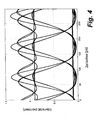
- FIG. 1 shows an example of eye diagrams showing the Associated with receivers 107, 108 and 109 in Fig. 1, respectively 2 the receiver 107, the eye diagram 3 the receiver 108 and the eye diagram according to FIG. 4 is assigned to the receiver 109.
- the differences are obvious and represent different signal qualities, which in turn cause different bit error ratios (BER: bit error ratio).
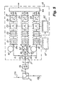
- FIG. 5 shows a block diagram of a test device 10 for Quality assessment of signals, for example in a fully optical Network 101 can be transmitted in any way.
- This test device 10 should, for example, directly behind the optical switching unit 119 (FIG. 1) in the Line 126 inserted.
- the insertion takes place by means of a beam splitter 11, which is a small fraction of that on line 126 Derives carrier beam on the branch 13, e.g. 1% of his performance.
- the branched partial beam passes through a filter 14 that the unwanted Filtered out portions, for example the "yellow” (dotted arrows) carrier beam (corresponding to Fig. 1), so that only the "blue” (solid arrows) Test beam S remains for the test.
- the test device 10 in the embodiment shown comprises one (Further) beam splitter 21 with three outputs 22, 23, 24 for the same sharing Splitting the test beam S, three identically constructed receivers 31, 32, 33, two different transmission elements 41, 42, an attenuator 43, one Logic circuit 62 for controlling the receivers 31, 32, 33 and one Outputs 37, 38, 39 of the receivers 31, 32, 33 downstream Evaluation computer 44.
- a digital signal can be added to this Clock recovery unit 61 come.
- the transmission element 41 is connected between the first output 22 of the beam splitter 21 and the input 34 of the first receiver 31.
- the element 41 is, for example, an abnormal dispersion fiber. This means that the second term of the Taylor series of the propagation constant ⁇ of the carrier frequency responsible for the distortion of the signals is less than zero ( ⁇ 2 ⁇ 0). As a result, the transmission element 41 specifically causes (first) signal distortion of the respective beam S 1 passing through.
- the second transmission element 42 is connected between the second output 23 of the beam splitter 21 and the input 35 of the second receiver 32.
- Element 42 is also a fiber, but with normal dispersion ( ⁇ 2 > 0). Element 42 thus causes a second, different type of signal distortion of the passing beam S 2 . It is preferably required that the total dispersion through the two transmission elements 41 and 42 assume the same values.
- the transmission elements 41, 42 formed as fibers, each have, in addition to the different dispersions described, damping.
- the attenuator 43 is connected between the third output 24 of the beam splitter 21 and the input 36 of the third receiver 33. This weakens the intensity of the respective beam S 0 passing through by an adjustable amount, in particular to the same extent as the two fibers 41, 42. This has the effect that the partial beams S 1 , S 2 , S 0 are largely attenuated to the same extent. This can be exactly ensured if necessary by additional attenuators in the paths of the partial beams S 1 and / or S 2 .
- the attenuator 43 does not cause any dispersion of the signal and thus does not produce any signal distortion.
- the identically constructed receivers 31, 32, 33 each have one optoelectric converter 51, in particular a photodiode, optionally one Low pass filter 52, a signal sampler 53 and an analog / digital converter 54. These units are connected in series.
- the low pass filter 52 is not mandatory and can therefore be omitted; also other receiver variations are conceivable.
- the downstream of the receiver outputs 37, 38, 39 Evaluation computer 44 is any digital working computer unit Design type.
- the logic unit 62 is a control device for any Switching through the signal samplers 53. The sampling takes place with digital Signals preferably in synchronism with the signal clock. If this is not available, it can Sampling can also be done asynchronously.
- the test device 10 is both for suitable for digital as well as for analog signals. This will make the Transparency of the communication network 101 with regard to the used Bit rates and the types of modulation are taken into account.
- the test device 10 described so far works as follows:
- the test beam S coming from the filter 14 is divided by the beam splitter 21 into three partial beams S 1 , S 2 , S 0 each with approximately the same intensity and other properties.
- These partial beams pass through the transmission element 41, the transmission element 42 or the attenuator 43.
- they are deliberately differently distorted or not distorted.
- a sequence of assigned electrical intensity signals I 1 , I 2 , I 0 is obtained from the partial beams S 1 , S 2 , S 0 by the receivers 31, 32, 33.
- the partial beams arriving at the inputs 34, 35, 36 are converted into proportional electrical currents or voltages with the aid of the optoelectric converter 51.
- the currents or voltages are sampled in terms of pulses by the signal samplers 53, with each pulse being significantly shorter than the length of a bit in digital signals.
- the integral of the respective charge quantity is then output by the converters 54 at the outputs 37, 38, 39 as digital values of the respective beam intensity I 1 , I 2 , I 0 at the associated sampling times.
- the difference size 2B characterizes the influence of the Test beam S present at the input 15 of the test device 10 Phase changes. These phase changes can be from the modulator of the each associated transmitter (102 in the example of FIG. 1) originate from Non-linearities on the transmission lines already traversed, i.e. the Line 122 (in the example of Fig. 1).
- the sum size 2A supplies Statements about the "susceptibility" of the beam splitter 11 present waveform against dispersion-related distortions further lines to be run through.
- the test device 10 enables thus the determination of test variables on the quality of the transmission signals at any point in an optical transmission network (101), in particular also in the area of switching units 119. With earlier, known methods this was previously not possible.
- test devices 10 can be summarized in whole or in part in such a way that the test quantities accruing from these (10) are managed centrally as data and are evaluable. This can be used, for example, to provide statistical information about gain network behavior, or information about gradual changes. In the event of malfunctions or inadequate behavior, you can go on the targeted comparison of the existing data with the known structure of the Network 101 quickly identify the triggering weak points or errors.
- the invention enables simple and effective evaluation and monitoring of optical networks by anywhere in the Netzes quantitative statements about the quality of the available there Transmission signals can be determined.
- the type of these signals does not matter Role.
- the signals can be analog or digital, with any frequencies.
- the method according to the invention is thus suitable for any optical Participants transparent networks possible. Due to the possibility of Obtaining and comparing data on the signal qualities different parts of the network need to be localized if necessary Errors or weak points in the network are easily possible. This results in a Behavior that far exceeds that of previously known methods with similar Objective goes beyond.
Landscapes
- Physics & Mathematics (AREA)
- Electromagnetism (AREA)
- Engineering & Computer Science (AREA)
- Computer Networks & Wireless Communication (AREA)
- Signal Processing (AREA)
- Optical Communication System (AREA)
- Testing Of Optical Devices Or Fibers (AREA)
Abstract
Description
Die Erfindung betrifft eine Vorrichtung zur Prüfung der Qualität eines Übertragungssignals, das einem über einen Lichtwellenleiter laufenden Trägerstrahl aufmoduliert ist, entsprechend dem Oberbegriff von Anspruch 1. Die Erfindung betrifft ferner ein Verfahren zur Prüfung der Qualität eines solchen Übertragungssignals und die Verwendung der Vorrichtung bzw. des Verfahrens entsprechend dem Oberbegriff der anderen, unabhängigen Ansprüche.The invention relates to a device for checking the quality of a Transmission signal that a running over an optical fiber Carrier beam is modulated, according to the preamble of claim 1. The invention further relates to a method for checking the quality of a such transmission signal and the use of the device or Procedure according to the preamble of the other, independent Expectations.
Es sind optische Netze für Kommunikationszwecke und deren Bauelemente bekannt. Bei solchen Netzen konventioneller Bauart arbeiten nur die Übertragungsstrecken optisch, während die Knoten elektrisch aufgebaute Einrichtungen enthalten. Solche Netze benötigen zahlreiche optoelektrische und elektro-optische Wandler, was aufwendig ist. Andererseits ermöglicht diese Technik einen Ausgleich von auf den Übertragungsstrecken entstehenden Signalverzerrungen. Insbesondere bei digitalen Signalen ist eine exakte Signal-Regenerierung möglich.They are optical networks for communication purposes and their Components known. In such networks of conventional design only work the transmission links optically, while the nodes are built electrically Facilities included. Such networks require numerous optoelectric ones and electro-optical converters, which is expensive. On the other hand, this enables Technology to compensate for those arising on the transmission links Signal distortion. Precise signal regeneration is particularly important with digital signals possible.
Es sind ferner diverse Multiplexierungs-Techniken bekannt, durch die mehrere Übertragungskanäle auf einer gemeinsamen Leitung installierbar sind. Explizit genannt seien das Zeitmultiplex-Verfahren (TDM: time division multiplexing) und das Wellenlängen-Multiplex-Verfahren (WDM: wavelength division multiplexing). Diese Techniken erlauben eine mehrfache Ausnützung der vorhandenen Übertragungsleitungen. Dem steht ein erhöhter Aufwand für das Multiplexieren und Demultiplexieren gegenüber. Es besteht ferner die Gefahr unerwünschter Wechselwirkungen zwischen den verschiedenen Multiplex-Kanälen. Zur Verbesserung der allgemeinen Situation wurde normenmässig die sogenannte Synchrone Digitale Hierarchie (SDH) eingeführt, durch die eine Vielzahl von Überwachungsmöglichkeiten in Weitverkehrsnetzen ermöglicht wird.Various multiplexing techniques are also known, through which multiple transmission channels can be installed on a common line. Time division multiplexing (TDM: time division multiplexing) and the wavelength division multiplexing method (WDM: wavelength division multiplexing). These techniques allow multiple uses the existing transmission lines. This represents an increased effort for versus multiplexing and demultiplexing. There is also the Risk of undesirable interactions between the different Multiplex channels. To improve the general situation the so-called Synchronous Digital Hierarchy (SDH) was introduced as standard, through the multitude of monitoring options in wide area networks is made possible.
Es sind weiter die Einflüsse bekannt, die auf optischen Übertragungsstrecken die maximal erreichbaren Reichweiten beeinflussen bzw. begrenzen. Solche Einflüsse sind insbesondere:
- Die Faserdämpfung, welche die optische Leistung exponentiell mit der Streckenlänge reduziert.
- Die chromatische Dispersion (GVD: Group-Velocity Dispersion) und der stochastische Effekt der Polarisationsdispersion (PMD: Polarization Mode Dispersion), welche die Signalformen verändern, ohne dabei die mittlere Leistung pro Übertragungskanal zu beeinflussen.
- Die stimulierte Brillouin-Streuung (SBS), welche bei unidirektionalem Betrieb die Wellen zusätzlich, und zwar nichtlinear, dämpft.
- Die stimulierte Raman-Streuung (SRS), welche einige Lichtwellen zu Lasten anderer, ebenfalls nichtlinear, verstärkt .
- Die Selbstphasenmodulation (SPM: Self-Phase Modulation) und die Kreuzphasenmodulation (XPM: Cross-Phase Modulation), welche, wie auch die chromatische Dispersion GVD, die Phase der jeweiligen Lichtwelle verändern, was bei einem Direktempfang (DD: Direct Detection) jedoch keinen direkten Einfluss auf den Signalverlauf hat.
- The fiber attenuation, which reduces the optical power exponentially with the track length.
- The chromatic dispersion (GVD: Group Velocity Dispersion) and the stochastic effect of the polarization dispersion (PMD: Polarization Mode Dispersion), which change the signal shapes without affecting the average power per transmission channel.
- The stimulated Brillouin scattering (SBS), which additionally dampens the waves in unidirectional operation, namely non-linearly.
- The stimulated Raman scattering (SRS), which amplifies some light waves at the expense of others, also non-linear.
- The self-phase modulation (SPM: Self-Phase Modulation) and the cross-phase modulation (XPM: Cross-Phase Modulation), which, like the chromatic dispersion GVD, change the phase of the respective light wave, but none with direct reception (DD: Direct Detection) has a direct influence on the signal curve.
Es sind weiter auch Kriterien bekannt, wie die Qualität bzw. Güte von Übertragungsstrecken quantifizierbar sind. Hierzu ist vor allem die Bitfehlerwahrscheinlichkeit (BER: Bit Error Ratio) zu nennen, die durch Senden und Empfangen eines bekannten Bitmusters, d. h. einer bekannten Folge von "Einsen" und "Nullen", leicht ermittelbar ist. Weiter ist der Q-Faktor zu erwähnen , der mit der Wahrscheinlichkeitsdichte-Funktion des die Signale überlagernden Rauschens zusammenhängt.Criteria are also known, such as the quality or quality of Transmission lines are quantifiable. This is especially the Bit error ratio (BER) to be mentioned by sending and receiving a known bit pattern, i. H. a known episode of "Ones" and "zeros" is easy to determine. The Q factor should also be mentioned , with the probability density function of the signals superimposed Noise is related.
Die Publikation von L. Rapp, "Freie Fahrt auf der Datenautobahn", Computerworld, Nr. 22, 25. Mai 1998 gibt einen guten Überblick über die wichtigsten Aspekte zukünftiger, volloptischer Weitverkehrsnetze. Diese Netze stehen demnächst den erwähnten konventionellen, optischen Netzen gegenüber, wobei optische Verstärker die bisherigen elektronischen Verstärker ersetzen. The publication by L. Rapp, "Free travel on the information superhighway", Computerworld, No. 22, May 25, 1998 gives a good overview of the most important aspects of future, fully optical long-distance networks. These networks will soon be the conventional optical networks mentioned opposite, optical amplifiers being the previous electronic amplifiers replace.
Weiter sei die Publikation von K. Müller et al, "Application of Amplitude Histograms for Quality of Service Measurements of Optical Channels and Fault Identification", ECOC'98, pp. 707-708, 20.-24. September 1998, Madrid, Spain, genannt. Diese Schrift behandelt eine Methode zum Charakterisieren der Qualität von Übertragungskanälen auf optischen Leitungen. Diese Methode basiert auf der Ermittlung von Amplituden-Histogrammen, die durch asynchrones Abtasten gewonnen werden. Sie erlaubt allerdings nur Angaben über die zu erwartende Bitfehlerwahrscheinlichkeit, die erzielbar wäre, wenn sich der Empfänger am Ort der Messung befände. Für die Lokalisierung von Fehlerquellen ist die Methode jedoch kaum geeignet.Furthermore, the publication by K. Müller et al, "Application of Amplitude Histograms for Quality of Service Measurements of Optical Channels and Fault Identification ", ECOC'98, pp. 707-708, September 20-24, 1998, Madrid, Spain. This document deals with a method for Characterize the quality of transmission channels on optical Cables. This method is based on the determination of amplitude histograms, which are obtained by asynchronous sampling. she allows however, only information about the expected bit error probability, the would be achievable if the receiver were at the location of the measurement. For the However, the method is hardly suitable for localizing sources of error.
Insgesamt zeigt sich, dass mit den Methoden des dargelegten Standes der Technik eine einwandfreie Überwachung der Qualität optischer Netze kaum möglich ist. Insbesondere sind die Einflüsse von Selbstphasen- und Kreuzphasenmodulationen kaum zu erfassen. Damit bleiben solche Einflüsse leicht unbemerkt und können damit sehr heimtückische Störquellen bilden. Dies kann in volloptischen Netzen (aber auch auf Punkt-zu-Punkt-Verbindungen) zu echten Problemen führen. Zu diesem Aspekt wird auf die Publikation von L. Rapp, "Distortion of SCM Signals due to cross-phase modulation in transparent optical networks", Proc. Workshop on All-Optical Networks, Zagreb, Kroatien, S. 143 - 151, 6. bis 8. Mai 1998, hingewiesen. Weiter ergibt sich aus dem Stand der Technik und der Existenz der genannten, nicht erfassbaren Störquellen, dass eine systematische Fehlersuche beim Auftreten von Störungen kaum möglich ist.Overall, it is shown that with the methods of the State of the art proper monitoring of the quality of optical Networks is hardly possible. In particular, the influences of self-phase and cross-phase modulations can hardly be detected. That leaves them Influences easily go unnoticed and can be very insidious sources of interference form. This can be done in fully optical networks (but also on point-to-point connections) lead to real problems. On this aspect, the Publication by L. Rapp, "Distortion of SCM Signals due to cross-phase modulation in transparent optical networks ", Proc. Workshop on All-Optical Networks, Zagreb, Croatia, pp. 143-151, May 6-8, 1998. Furthermore, the state of the art and the existence of the named unrecognizable sources of interference that a systematic troubleshooting of the Disruption is hardly possible.
Der vorliegenden Erfindung liegt die Aufgabe zugrunde, eine Vorrichtung bzw. ein verbessertes Verfahren anzugeben, mit deren Hilfe eine möglichst vollständige und zuverlässige Prüfung von optisch über beliebige Lichtwellenleiter übertragenen Signalen durchführbar ist. Hierdurch soll die Signalqualität in beliebigen optischen Netzen, insbesondere auch in volloptischen Netzen, einwandfrei und umfassend überwachbar werden. Diese Vorrichtung bzw. dieses Verfahren sollen so geartet sein, dass im Falle von Störungen die Fehlerstellen im Netz rasch und sicher lokalisierbar sind. The present invention has for its object a Specify device or an improved method, with the help of a The most complete and reliable possible inspection of any optical Optical fiber transmitted signals is feasible. This is supposed to Signal quality in any optical network, especially in fully optical networks, can be monitored properly and comprehensively. This Device or this method should be such that in the case of Faults that can quickly and securely locate fault points in the network.
Die erfindungsgemässe Lösung dieser Aufgabe wird durch die unabhängigen Patentansprüche definiert. Die abhängigen Patentansprüche geben bevorzugte Ausgestaltungen der Erfindung an.The inventive solution to this problem is achieved by independent claims defined. The dependent claims give preferred embodiments of the invention.
Die erfindungsgemässe Vorrichtung bzw. das erfindungsgemässe Verfahren zur Prüfung der Qualität von Übertragungssignalen auf Faserleitungen in volloptischen Netzen ist relativ einfach und erlaubt eine quantitative Erfassung sämtlicher bekannter Verzerrungsarten, insbesondere auch von Verzerrungen, die auf induzierten Phasenänderungen beruhen. Diese Erfassung ist sowohl bei digitalen als auch bei analogen Signalen möglich, so dass das volloptische Netz für alle Netzteilnehmer transparent betreibbar ist. Hierauf lässt sich daher ein netzweites Überwachungssystem aufbauen, mit dessen Hilfe quantifizierende Werte bereitgestellt werden können für Langzeituntersuchungen, Bewertungen, Vergleiche, usw.The device according to the invention or the device according to the invention Procedure for checking the quality of transmission signals Fiber lines in fully optical networks are relatively simple and allow one quantitative recording of all known types of distortion, in particular also of distortions based on induced phase changes. This Detection is possible with both digital and analog signals, so that the fully optical network can be operated transparently for all network participants. A network-wide monitoring system can therefore be built on this with whose help quantifying values can be provided for Long-term examinations, evaluations, comparisons, etc.
Ausführungsbeispiele der Erfindung werden nachstehend anhand der folgenden Figuren näher beschrieben.Embodiments of the invention are described below of the following figures.
Es zeigen:
Figur 1 zeigt schematisch und als Beispiel den Aufbau eines sehr
einfachen, volloptischen Kommunikationsnetzes 101 für den Weitverkehr
zwischen beispielsweise fünf verschiedenen Regionen. Gezeigt sind insgesamt
vier verschiedene Sender 102 bis 105 (Tx: transmitter) von einer grösseren
Mehrzahl von Sendern und vier verschiedene Empfänger 106 bis 109 (Rx:
receiver) von einer ebenfalls grösseren Anzahl von Empfängern. Die Sender
102, 103 und 105 sind über regionale Multiplexer 112 bzw. 115 mit abgehenden
Leitungen 122 bzw. 125 verbunden, der Sender 104 direkt mit einer
abgehenden Leitung 124. Die Empfänger106, 107 und 108, 109 sind
entsprechend über regionale Demultiplexer 116 bzw. 118 mit ankommenden
Leitungen 126 bzw. 128 verbunden. Die abgehenden 122, 124, 125 und die
ankommenden Leitungen 126, 128 sind über eine optische Schalteinheit 119
(OXC: optical cross connect) beliebig miteinander verbindbar.Figure 1 shows schematically and as an example the structure of a very
simple, fully optical communication network 101 for long-distance traffic
between five different regions, for example. All are shown
four
Der Begriff "volloptisch" für das Netz 101 bedeutet, dass ausser den Sendern 102 bis 105 und den Empfängern 106 bis 109 alle anderen Elemente rein optisch funktionieren; insbesondere arbeiten notwendige Verstärker als optische Verstärker, die den jeweiligen eingangsseitigen Signalpegel wieder anheben. Desgleichen funktioniert die optische Schalteinheit 119 rein optisch. Weiter können Wellenlängenkonverter im Netz vorhanden sein. Dies bedeutet, dass im eigentlichen Netz keine optoelektrischen oder elektro-optischen Wandler vorhanden sind.The term "fully optical" for the network 101 means that in addition to the Transmitters 102-105 and receivers 106-109 all other elements function purely optically; in particular, necessary amplifiers work as optical amplifiers that reflect the respective input signal level lift. Likewise, the optical switching unit 119 functions purely optically. Wavelength converters can also be present in the network. This means, that in the actual network there are no optoelectric or electro-optical Transducers are present.
Die Leitungen 122, 124, 125, 126, 128 sind optische Faserleitungen,
bevorzugt Einmoden-Fasern. Als Beispiel haben die Leitungen 122 und 125 je
eine Länge von 90 km und sind dispersionsverschoben (DSF: dispersion shifted
fiber). Die Leitung 124 ist relativ kurz und bewirkt keine Signalverzerrungen. Die
Leitungen 126, 128 bestehen aus Standardfasern (SSMF: standard single
mode fiber) und haben jeweils eine Länge von 50 km. Die Signalleistung auf
diesen ankommenden Leitungen 126, 128 wird als so gering angenommen,
dass eventuell auftretende nichtlineare Effekte vernachlässigbar bleiben.The
Als Signalträger dienen auf der Leitung 122 zwei Trägerstrahlen
unterschiedlicher Frequenzen, die mit "blau" (durchgezogene Pfeile) und "rot"
(gestrichelte Pfeile) bezeichnet seien. Diese Trägerstrahlen sind zur
Übermittlung von Signalen beliebig moduliert, beispielsweise
intensitätsmoduliert und digital mit vorgegebenem Takt. Auf der Leitung 125
dienen zwei Trägerstrahlen mit weiteren Frequenzen als Signalträger, von
denen nur der Trägerstrahl "grün" (strichpunktierte Pfeile) gezeigt ist. Auf der
Leitung 124 wird schliesslich ein fünfter Trägerstrahl "gelb" (punktierte Pfeile)
verwendet. Two carrier beams serve as signal carriers on
Die Signalträger und die angeordneten Signale passieren
weitgehend unabhängig voneinander die Schalteinheit 119. Der "rote" und
"grüne" Strahl erreichen über Leitung 128 den Demultiplexer 118, der "blaue"
und "gelbe" Strahl über die Leitung 126 den Demultiplexer 116.The signal carriers and the arranged signals pass
Switching unit 119 is largely independent of one another. The "red" and
The "green" beam reaches the
Zur Klarstellung sei betont, dass unter dem Begriff "Strahl" hier jeglicher optische Transportmechanismus zu verstehen ist, der auf einem beliebigen, optischen Übertragungsmedium einsetzbar ist, insbesondere auf einem Lichtwellenleiter in der Form einer Einmoden-Lichtleitfaser. Die Farbbezeichnungen "rot", "blau" usw. dienen als optische Wellenlängen- bzw. Frequenz-Angaben für den jeweiligen Strahl. Im betrachteten, beispielhaften Netz 101 liegen alle Wellenlängen im dritten Übertragungsfenster bei 1550 mm. Die Strahlen selbst sind zum Zwecke der Informations- bzw. Signalübertragung moduliert, wobei die Art der Modulation beliebig sein kann, insbesondere digital oder analog.For clarification it should be emphasized that under the term "beam" here any optical transport mechanism to be understood that is on a any optical transmission medium can be used, especially on an optical fiber in the form of a single-mode optical fiber. The Color names "red", "blue" etc. serve as optical wavelength or Frequency information for the respective beam. In the considered, exemplary Network 101 all wavelengths in the third transmission window are 1550 mm. The rays themselves are for the purpose of information or signal transmission modulated, the type of modulation can be arbitrary, especially digital or analog.
Insbesondere auf den langen, abgehenden Leitungen 122, 125
treten wegen der notwendigen erheblichen Sendeleistungen auf den Strahlen
nichtlineare Effekte auf. Auf der Leitung 122 beruhen diese auf
Phasenänderungen der Signale durch Selbstphasenmodulation (SPM) und
Kreuzphasenmodulation (XPM) zwischen den beiden aktiven Strahlen "rot" und
"blau". Auf der Leitung 125 tritt nur eine Selbstphasenmodulation (SPM) auf, da
nur der "grüne" Strahl aktiv ist.Especially on the long,
Durch alle Wechselwirkungen und Effekte im Netz 101 insgesamt
ergeben sich an den Empfängern 106 bis 109 unterschiedliche und im
allgemeinen ständig wechselnde Signalverzerrungen, die für digitale Signale
durch sogenannte Augendiagramme sichtbar gemacht werden können. Die
Figuren 2, 3, 4 zeigen Beispiele von Augendiagrammen, welche den
Empfängern107, 108 bzw. 109 in Fig. 1 zugeordnet sind, wobei das
Augendiagramm gemäss Fig. 2 dem Empfänger 107, das Augendiagramm
gemäss Fig. 3 dem Empfänger 108 und das Augendiagramm gemäss Fig. 4
dem Empfänger 109 zugeordnet ist. Die Unterschiede sind offensichtlich und
repräsentieren unterschiedliche Signal-Qualitäten, die wiederum
unterschiedliche Bitfehlerwahrscheinlichkeiten (BER: bit error ratio) bedingen. Through all interactions and effects in network 101 as a whole
result at the
Die gezeigten Unterschiede sind auf den unterschiedlichen Einfluss
nichtlinearer Effekte auf den Leitungen 122, 124 und 125 zurückzuführen.
Durch Messungen können diese Störeinflüsse aber nur lokalisiert werden, wenn
an den Eingängen oder Ausgängen der optischen Schalteinheit 119 registriert
wird, dass relevante Lichtwellenparameter, in diesem Falle die Phase,
unterschiedlich stark verändert wurden. Mit Hilfe der bekannten Verfahren, d.h.
Verfahren des Standes der Technik, sind jedoch an diesen Stellen keine
Unterschiede auszumachen. Die Störquellen werden daher fälschlicherweise
bei den nachfolgenden Leitungen 126 und 128 vermutet.The differences shown are due to the different influence
nonlinear effects on
Figur 5 zeigt ein Blockschaltbild einer Prüfvorrichtung 10 zur
Qualitätsbeurteilung von Signalen, die beispielsweise in einem volloptischen
Netz 101 über beliebige Wege übertragen werden. Diese Prüfvorrichtung 10
soll beispielsweise direkt hinter der optischen Schalteinheit 119 (Fig. 1) in die
Leitung 126 eingefügt sein. Das Einfügen erfolgt mittels eines Strahlteilers 11,
der einen geringen Anteil von dem auf der Leitung 126 vorhandenen
Trägerstrahl auf den Abzweig 13 ableitet, z.B. 1 % seiner Leistung. Der
abgezweigte Teilstrahl durchläuft ein Filter 14, das die nicht gewünschten
Anteile herausfiltert, beispielsweise den "gelben" (punktierte Pfeile) Trägerstrahl
(entsprechend Fig. 1), so dass allein der "blaue" (durchgezogene Pfeile)
Prüfstrahl S für die Prüfung übrig bleibt.FIG. 5 shows a block diagram of a
Die Prüfvorrichtung 10 in der gezeigten Ausgestaltung umfasst einen
(weiteren) Strahlteiler 21 mit drei Ausgängen 22, 23, 24 zum gleichteiligen
Aufteilen des Prüfstrahles S, drei gleich aufgebaute Empfänger 31, 32, 33, zwei
unterschiedliche Übertragungselemente 41, 42, ein Dämpfungsglied 43, eine
Logikschaltung 62 zum Steuern der Empfänger 31, 32, 33 und einen den
Ausgängen 37, 38, 39 der Empfänger 31, 32, 33 nachgeschalteten
Auswerterechner 44. Hierzu kann ergänzend für digitale Signale eine
Taktrückgewinnungseinheit 61 kommen.The
Das Übertragungselement 41 ist zwischen den ersten Ausgang 22
des Strahlteilers 21 und den Eingang 34 des ersten Empfängers 31 geschaltet.
Das Element 41 ist beispielsweise eine Faser mit anormaler Dispersion. Dies
bedeutet, dass der für die Verzerrung der Signale verantwortliche zweite Term
der Taylor-Reihe der Ausbreitungskonstante β der Trägerfrequenz kleiner Null
ist (β2 < 0). Hierdurch bewirkt das Übertragungselement 41 gezielt eine (erste)
Signalverzerrung des durchlaufenden, jeweiligen Strahls S1.The
Das zweite Übertragungselement 42 ist zwischen den zweiten
Ausgang 23 des Strahlteilers 21 und den Eingang 35 des zweiten Empfängers
32 geschaltet. Das Element 42 ist ebenfalls eine Faser, jedoch mit normaler
Dispersion (β2 > 0). Damit bewirkt das Element 42 gezielt eine zweite, anders
geartete Signalverzerrung des durchlaufenden, jeweiligen Strahls S2. Bevorzugt
wird dabei verlangt, dass die Gesamtdispersion durch die beiden
Übertragungselemente 41 und 42 die gleichen Werte annehmen.The
Die Übertragungselemente 41, 42, ausgebildet als Fasern, weisen
neben den beschriebenen, unterschiedlichen Dispersionen jeweils auch eine
Dämpfung auf. Aus diesem Grund ist zwischen den dritten Ausgang 24 des
Strahlteilers 21 und den Eingang 36 des dritten Empfängers 33 das
Dämpfungsglied 43 geschaltet. Dieses schwächt die Intensität des
durchlaufenden, jeweiligen Strahls S0 um einen einstellbaren Betrag,
insbesondere gleich stark wie die beiden Fasern 41, 42. Hierdurch wird bewirkt,
dass die Teilstrahlen S1, S2, S0 weitgehend gleich stark gedämpft werden.
Durch weitere Dämpfungsglieder in den Pfaden der Teilstrahlen S1 und/oder S2
kann dies notfalls exakt sichergestellt werden. Das Dämpfungsglied 43 bewirkt
keine Dispersion des Signals und erzeugt damit keine Signalverzerrung.The
Die gleich aufgebauten Empfänger 31, 32, 33 weisen jeweils einen
optoelektrischen Wandler 51 auf, insbesondere eine Fotodiode, wahlweise ein
Tiefpassfilter 52, einen Signalabtaster 53 und einen Analog-/Digital-Wandler 54.
Diese Einheiten sind in Serie geschaltet. Das Tiefpassfilter 52 ist nicht
zwingend und kann somit weggelassen werden; auch andere Empfänger-Variationen
sind denkbar.The identically constructed
Der den Empfängerausgängen 37, 38, 39 nachgeschaltete
Auswerterechner 44 ist eine digital arbeitende Computereinheit beliebiger
Bauart. Die Logikeinheit 62 ist eine Steuerungsvorrichtung zum beliebigen
Durchschalten der Signalabtaster 53. Die Abtastung erfolgt bei digitalen
Signalen bevorzugt synchron zum Signaltakt. Liegt dieser nicht vor, kann die
Abtastung aber auch asynchron erfolgen.The downstream of the receiver outputs 37, 38, 39
Durch das asynchrone Abtasten ist die Prüfvorrichtung 10 sowohl für
digitale als auch für analoge Signale geeignet. Hierdurch wird der genannten
Transparenz des Kommunikationsnetzes 101 bezüglich der eingesetzten
Bitraten und der Modulationsarten Rechnung getragen. Liegen digitale Signale
vor, dann kann mit Hilfe der Taktrückgewinnungseinheit 61 stichprobenartig zu
den potentiellen Signalabtastzeitpunkten bei den Empfängern 106 bis 109
gearbeitet werden. Der Takt für diese Stichproben kann dann wesentlich
langsamer sein als die Taktfrequenz des Signals. Allerdings ist dafür zu sorgen,
dass bei den Empfängern 31, 32, 33 die jeweiligen Gruppenlaufzeiten alle
gleich sind.Due to the asynchronous scanning, the
Die bisher beschriebene Prüfvorrichtung 10 arbeitet wie folgt: Der
vom Filter 14 herkommende Prüfstrahl S wird durch den Strahlteiler 21 in drei
Teilstrahlen S1, S2, S0 jeweils etwa gleicher Intensität und sonstiger
Eigenschaften aufgeteilt. Diese Teilstrahlen durchlaufen das
Übertragungselement 41, das Übertragungselement 42 bzw. das
Dämpfungsglied 43. Hierbei werden sie gezielt unterschiedlich verzerrt bzw.
nicht verzerrt.The
Durch die Empfänger 31, 32, 33 wird aus den Teilstrahlen S1, S2, S0
eine Folge zugeordneter, elektrischer Intensitätssignale I1, I2, I0 gewonnen.
Hierzu werden die an den Eingängen 34, 35, 36 ankommenden Teilstrahlen mit
Hilfe der optoelektrischen Wandler 51 in proportionale elektrische Ströme bzw.
Spannungen gewandelt. Nach dem Eliminieren eventuell vorhandener
Störfrequenzen durch die Filter 52 werden die Ströme bzw. Spannungen durch
die Signalabtaster 53 impulsmässig abgetastet, wobei jeder Puls wesentlich
kürzer ist als die Länge eines Bits bei digitalen Signalen. Das Integral der
jeweiligen Ladungsmenge wird dann nach Analog/Digital-Wandlung durch die
Wandler 54 an den Ausgängen 37, 38, 39 als Digitalwerte der jeweiligen
Strahlintensität I1, I2, I0 zu den zugehörigen Abtastzeitpunkten ausgegeben. A sequence of assigned electrical intensity signals I 1 , I 2 , I 0 is obtained from the partial beams S 1 , S 2 , S 0 by the
Der Auswerterechner 44 ermittelt aus den jeweils drei zeitlich
zusammengehörenden Intensitätswerten I1, I2, I0 jeweils zwei Grössen als Mass
für die Qualität der Signalübertragung an der Stelle des Strahlteilers 11. Diese
Grössen sind bevorzugt:
Mathematisch bzw. theoretisch ergeben sich diese Grössen aus den
physikalischen Gegebenheiten der Lichtwellen-Ausbreitung in den
unterschiedlichen Medien der Übertragungselemente 41, 42, des
Dämpfungsgliedes 43, und unter den bereits genannten Einschränkungen der
Prüfvorrichtung von Figur 5 wie Gleichheit der Teilstrahlen S1, S2, S0 usw.Mathematically or theoretically, these quantities result from the physical conditions of the light wave propagation in the different media of the
Die Differenz-Grösse 2B kennzeichnet den Einfluss der bereits im
Prüfstrahl S am Eingang 15 der Prüfvorrichtung 10 vorhandenen
Phasenänderungen. Diese Phasenänderungen können vom Modulator des
jeweils zugeordneten Senders (102 im Beispiel von Fig. 1) herrühren oder von
Nichtlinearitäten auf den bereits durchlaufenen Übertragungsleitungen, d.h. der
Leitung 122 (im Beispiel von Fig. 1). Die Summen-Grösse 2A liefert hingegen
Aussagen über die "Anfälligkeit" der an der Stelle des Strahlteilers 11
vorliegenden Signalform gegenüber dispersionsbedingten Verzerrungen auf
weiteren, noch zu durchlaufenden Leitungen. Die Prüfvorrichtung 10 ermöglicht
damit die Ermittlung von Prüfgrössen über die Qualität der Übertragungssignale
an beliebigen Stellen eines optischen Übertragungsnetzes (101), insbesondere
auch im Bereich von Schalteinheiten 119. Mit früheren, bekannten Methoden
war dies bisher nicht möglich.The difference size 2B characterizes the influence of the
Test beam S present at the
Es ist nun sinnvoll, durch laufend wiederholte Messungen eine
Datensammlung für die Signalqualitäten am jeweiligen Messort zu gewinnen.
Diese Sammlung ermöglicht Aussagen über die Statistik von
Signalverzerrungen, über schleichende Veränderungen auf den zugeordneten
Übertragungsleitungen, den optischen Schalteinheiten 119 usw. Weiter lässt
sich durch den koordinierten Einsatz mehrerer, über das ganze Netz 101
geeignet verteilter Prüfvorrichtungen 10 dieses Netz vorübergehend oder auch
dauernd überwachen. Durch eine computergestützte Managementanordnung
lassen sich die Prüfvorrichtungen 10 ganz oder teilweise so zusammenfassen,
dass die bei diesen (10) anfallenden Prüfgrössen als Daten zentral verwalt- und
auswertbar sind. Hiermit lassen sich beispielsweise statistische Angaben über
das Netzverhalten gewinnen, oder Angaben über schleichende Veränderungen.
Im Fall von Störungen oder ungenügendem Verhalten lassen sich weiter durch
den gezielten Vergleich der vorhandenen Daten bei bekanntem Aufbau des
Netzes 101 die auslösenden Schwach- oder Fehlerstellen schnell eruieren.It now makes sense to carry out a repeated measurement
To collect data for the signal qualities at the respective measuring location.
This collection enables statements about the statistics of
Signal distortion, via gradual changes on the assigned
Transmission lines, the optical switching units 119, etc. lets
through the coordinated use of several, over the entire network 101
suitably distributed
Ausser den bereits genannten Variationen des vorstehend beschriebenen Ausführungsbeispiels der Erfindung gibt es eine erhebliche Anzahl weiterer Möglichkeiten von Änderungen, die innerhalb des Erfindungsgedankens liegen. Nachfolgend werden einige dieser Variationen explizit genannt:
Die Prüfvorrichtung 10 lässt sich in beliebig aufgebauten, optischen Kommunikationsnetzen 101 einsetzen. Solche Netze können eine Mehrzahl von Schalteinheiten 119, eine Vielzahl von Sendern 102 - 105 und Empfängern 106 - 109, und unterschiedliche Arten von Lichtleitfasern aufweisen. Im Minimum kann unter einem solchen Netz 101 aber auch eine einzige Punkt-zu-Punkt-Verbindung verstanden werden. Weiter ist es nicht notwendig, dass das Netz 101 "volloptisch" ist; (einzelne) elektro-optische und/oder optoelektrische Wandler innerhalb des Netzes 101 schaden nicht und haben keinen Einfluss auf die beschriebene Art der Signalqualitäten-Ermittlung.Die Übertragungselemente der Prüfvorrichtung 10 wurden anhand von Figur 5 als Fasern mit anormaler Dispersion bzw. mit normaler Dispersion beschrieben. Anstelle dieser Fasern lassen sich auch ähnlich wirkende, andere Elemente einsetzen. Solche Elemente sind beispielsweise dispersionsbehaftete "Chirped Gratings" oder Elemente mit Polarisationsdispersion (PMD). Grundsätzlich kommt es darauf an, eine Frequenzabhängigkeit der Gruppenlaufzeit der Signale zu nutzen, d.h. unterschiedliche chromatische Dispersionen.
- The
test device 10 can be used in optical communication networks 101 of any design. Such networks can have a plurality of switching units 119, a plurality of transmitters 102-105 and receivers 106-109, and different types of optical fibers. Such a network 101 can also be understood as a minimum of a single point-to-point connection. Furthermore, it is not necessary for the network 101 to be “fully optical”; (Individual) electro-optical and / or optoelectric converters within the network 101 do no harm and have no influence on the described type of signal quality determination. - The
transmission elements test device 10 have been described with reference to FIG. 5 as fibers with abnormal dispersion or with normal dispersion. Instead of these fibers, other elements with a similar effect can also be used. Such elements are, for example, dispersion-based "chirped gratings" or elements with polarization dispersion (PMD). Basically, it is important to use a frequency dependence of the group delay of the signals, ie different chromatic dispersions.
Sind die Übertragungselemente 41, 42 Fasern, dann bilden sie mit ihrer jeweiligen Dispersion und Dämpfung die Art und Weise nach, wie die Signale durch die Lichtwellenleiter im Netz 101 abgeschwächt werden und unerwünschte Verzerrungen erleiden. Sind die Übertragungselemente 41, 42 optische Filter, dann ist die Nachbildung der signalverzerrenden Elemente des Netzes nicht so offensichtlich. Sie ist aber durchaus geeignet, die Phase und die Intensität der beeinflussten Signale zu beurteilen.
Die Prüfvorrichtung 10 wurde anhand von Fig. 5 mit drei Teilstrahlen S1, S2, S0 und drei Empfängern 31bis 33 beschrieben. Dies ist die bevorzugte Konfiguration, die es erlaubt, die untersuchten Signale vollständig zu charakterisieren.
- The
test device 10 was described with reference to FIG. 5 with three partial beams S 1 , S 2 , S 0 and threereceivers 31 to 33. This is the preferred configuration that allows the signals under investigation to be fully characterized.
Es ist nun grundsätzlich möglich, auf einen der Teilstrahlen S2 oder
S0 und die zugeordneten Empfänger 32 bzw. 33 zu verzichten. Im Fall des
Wegfalls von S2 ergibt sich im Auswerterechner 44 ein Resultat, welches keine
Unterscheidung der Verzerrungsursachen "Phasenverlauf' und "zeitlicher
Verlauf der Intensität" ermöglicht. Dieses Resultat kann für gewisse Zwecke
genügen und Auskunft geben über die Anfälligkeit des untersuchten Signals
gegenüber dem Einfluss der chromatischen Dispersion.In principle, it is now possible to dispense with one of the partial beams S 2 or S 0 and the associated
Im Fall des Wegfalls von S0 liefert der Vergleich der verbleibenden
elektrischen Intensitätswerte I1 und I2 im Auswerterechner 44 weiterhin die
Differenzgrösse 2B,
Hiermit ist weiterhin eine exakte Aussage über den Phasenverlauf möglich. Da jedoch die Summengrösse 2A nicht anfällt, kann nicht beurteilt werden, wie gross die Verzerrungen sind, die nur vom Intensitätsverlauf abhängen.
- Bei einer weiteren Variante können mehr als drei Teilstrahlen S1,
S2, S0 verwendet werden (allgemein eine Mehrzahl N). Sinnvoll ist es
beispielsweise, in den verschiedenen
Signalpfaden Fasern - In Figur 5 wurde der Strahlteiler 21 so beschrieben, dass er drei
etwa gleich starke Teilstrahlen S1, S2, S0 erzeugt, und dass diese Teilstrahlen
jeweils etwa gleich stark gedämpft werden durch die
Elemente durch den Strahlteiler 21 können ungleich starke Dämpfungen durch dieElemente das Dämpfungsglied 43 eingespart werden, indem der Teilstrahl S0 wesentlich intensitätsschwächer gemacht wird als die Teilstrahlen S1, S2. - Mittels rechnerischer Korrekturen lassen sich Unterschiede in der Stärke der Teilstrahlen S1, S2, S0, im Verhalten der Empfänger 31, 32, 33, usw. ausgleichen. Es ist damit möglich, eine physikalisch nicht optimal abgestimmte Prüfvorrichtung für die Gewinnung der gewünschten Prüfgrössen, insbesondere 2A, 2B, rechnerisch zu verbessern. Theoretisch lässt sich sogar mit unterschiedlich aufgebauten Empfängern 31, 32, 33 operieren.
- Während die bisher beschriebenen Varianten alle im wesentlichen
auf einer parallelen Verarbeitung der Teilstrahlen S1, S2, S0 entsprechend Fig. 5
basieren, kann die Verarbeitung jedoch grundsätzlich auch seriell erfolgen. Dies
wird anhand von Fig. 6 beschrieben: Der Prüfstrahl S wird hierbei nicht geteilt,
sondern durch einen ersten optischen
Schalter 71 sequentiell, insbesondere zyklisch mit kontinuierlichem Periodentakt, auf diedrei Ausgänge 72, 73, 74 geleitet und hierbei in Teilstrahl S1', S2' bzw. S0' umbenannt. Diese Teilstrahlen durchlaufen analog zu Fig. 5ein erstes Übertragungselement 41 mit anormaler Dispersion,ein zweites Übertragungselement 42 mit normaler Dispersion undein Dämpfungsglied 43 ohne Dispersionseigenschaften. Hiernach werden sie durch einen zweiten optischenSchalter 75 seriell einem einzigen Empfänger 31' zugeführt, der identisch zuden Empfängern vom Auswerterechner 44 übernommen werden. Der Empfänger 31' wird durch dieSteuereinheit 62 gesteuert, der gleichzeitig auch die synchrone Steuerung derSchalter - Fig. 7 zeigt eine Variante des Ausführungsbeispiels gemäss Fig.
6. Der wesentliche Unterschied zwischen beiden Ausführungen besteht darin,
dass bei der Variante gemäss Fig. 7
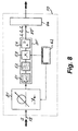
der optische Schalter 71 in der Vorrichtung gemäss Fig. 6 durch einen Strahlteiler 21 ersetzt wird, welcher die gleiche Funktion wie der Strahlteiler 21 in der Vorrichtung gemäss Fig. 5 hat. Ansonsten sind der Aufbau und die Funktionsweise der Variante gemäss Fig. 7 und des Ausführungsbeispiels gemäss Fig. 6 gleich. - Fig. 8 zeigt eine weitere Variante mit zyklischer Abtastung. Bei
dieser Variante sind die
Übertragungselemente Dieses Übertragungselement 81 kann beispielsweise realisiert sein durch mehrere optische Fasern mit unterschiedlichen Eigenschaften, die beliebig zusammenschaltbar sind und damit dem jeweils durchlaufenden Lichtstrahl S je nach Schaltstellung unterschiedliche Dispersion aufzwingen. Es kann sich aber auch um ein Element handeln, dessen Eigenschaften sich kontinuierlich verändern lassen.Die Steuereinheit 62steuert das Übertragungselement 81 und den nachgeschalteten Empfänger 31'. An dessen Ausgang 37' sinddann vom Auswerterechner 44 periodisch die der jeweiligen Einstellung des Übertragungselementes 81 zugeordneten, beispielsweise zyklisch auftretenden, elektrischen Intensitätswerte I1, I2, I0 und/oder eventuelle weitere Werte abgreifbar.
- In a further variant, more than three partial beams S 1 , S 2 , S 0 can be used (generally a plurality N). For example, it makes sense to use
fibers - In FIG. 5, the
beam splitter 21 was described in such a way that it generates three partial beams S 1 , S 2 , S 0 of approximately the same strength, and that these partial beams are each attenuated approximately equally by theelements beam splitter 21 unevenly strong attenuations can be compensated for by theelements attenuator 43 can be saved by making the partial beam S 0 much weaker in intensity than the partial beams S 1 , S 2 . - Computational corrections can be used to compensate for differences in the strength of the partial beams S 1 , S 2 , S 0 , in the behavior of the
receivers receivers - While the variants described so far are all essentially based on parallel processing of the partial beams S 1 , S 2 , S 0 according to FIG. 5, the processing can in principle also be carried out serially. This is described with reference to FIG. 6: the test beam S is not divided here, but is guided sequentially, in particular cyclically with a continuous period cycle, to the three
outputs 72, 73, 74 by a firstoptical switch 71 and in this case in partial beam S 1 ′, S 2 'or S 0 ' renamed. Analogously to FIG. 5, these partial beams pass through afirst transmission element 41 with abnormal dispersion, asecond transmission element 42 with normal dispersion and anattenuator 43 without dispersion properties. Thereafter, they are serially fed by a secondoptical switch 75 to a single receiver 31 ', which is identical to thereceivers evaluation computer 44, are then cyclically present in the output 37 '. The receiver 31 'is controlled by thecontrol unit 62, which at the same time also takes over the synchronous control of theswitches - FIG. 7 shows a variant of the exemplary embodiment according to FIG. 6. The essential difference between the two embodiments is that in the variant according to FIG. 7 the
optical switch 71 in the device according to FIG. 6 is replaced by abeam splitter 21 which has the same function as thebeam splitter 21 in the device according to FIG. 5. Otherwise, the structure and the mode of operation of the variant according to FIG. 7 and the exemplary embodiment according to FIG. 6 are the same. - 8 shows a further variant with cyclic scanning. In this variant, the
transmission elements transmission element 81 which is variable in its properties. This is shown by the combination of the symbols for optical fiber, adjustability and switch. Thistransmission element 81 can be realized, for example, by a plurality of optical fibers with different properties, which can be interconnected as desired and thus impose different dispersion on the light beam S passing through, depending on the switching position. However, it can also be an element whose properties can be changed continuously. Thecontrol unit 62 controls thetransmission element 81 and the downstream receiver 31 '. At its output 37 ', theevaluation computer 44 can then periodically tap the electrical intensity values I 1 , I 2 , I 0 and / or any further values associated with the respective setting of thetransmission element 81, for example cyclically.
Die Erfindung ermöglicht eine einfache und wirkungsvolle Bewertung und Überwachung von optischen Netzen, indem an beliebigen Orten des Netzes quantitative Aussagen über die Qualität der dort vorliegenden Übertragungssignale ermittelbar sind. Hierbei spielt die Art dieser Signale keine Rolle. Die Signale können analog oder digital sein, mit beliebigen Frequenzen. Damit ist die erfindungsgemässe Methode in beliebigen optischen, für die Teilnehmer transparenten Netzen möglich. Durch die Möglichkeit der Gewinnung und den Vergleich von Daten über die Signalqualitäten an unterschiedlichen Stellen des Netzes ist im Bedarfsfall eine Lokalisierung von Fehler- oder Schwachstellen des Netzes einfach möglich. Damit ergibt sich ein Verhalten, das weit über dasjenige vorbekannter Methoden mit ähnlicher Zielsetzung hinausgeht.The invention enables simple and effective evaluation and monitoring of optical networks by anywhere in the Netzes quantitative statements about the quality of the available there Transmission signals can be determined. The type of these signals does not matter Role. The signals can be analog or digital, with any frequencies. The method according to the invention is thus suitable for any optical Participants transparent networks possible. Due to the possibility of Obtaining and comparing data on the signal qualities different parts of the network need to be localized if necessary Errors or weak points in the network are easily possible. This results in a Behavior that far exceeds that of previously known methods with similar Objective goes beyond.
Claims (26)
wobei auf dem Lichtwellenleiter weitere Trägerstrahlen und/oder Übertragungssignale vorhanden sein können, und wobei Mittel (11, 14) vorgesehen sind zum verzerrungsfreien Abzweigen eines Prüfstrahls (S) vom genannten Trägerstrahl, dadurch gekennzeichnet, dass die Vorrichtung wenigstens folgende Einheiten umfasst,
wherein further carrier beams and / or transmission signals can be present on the optical waveguide, and wherein means (11, 14) are provided for the distortion-free branching of a test beam (S) from said carrier beam, characterized in that the device comprises at least the following units,
Priority Applications (4)
| Application Number | Priority Date | Filing Date | Title |
|---|---|---|---|
| ES99810108T ES2214002T3 (en) | 1999-02-09 | 1999-02-09 | QUALITY CONTROL OF AN OPTICAL TRANSMISSION SIGNAL. |
| EP99810108A EP1028548B1 (en) | 1999-02-09 | 1999-02-09 | Testing of the quality of an optical transmission signal |
| DE59908196T DE59908196D1 (en) | 1999-02-09 | 1999-02-09 | Checking the quality of an optical transmission signal |
| AT99810108T ATE257296T1 (en) | 1999-02-09 | 1999-02-09 | CHECKING THE QUALITY OF AN OPTICAL TRANSMISSION SIGNAL |
Applications Claiming Priority (1)
| Application Number | Priority Date | Filing Date | Title |
|---|---|---|---|
| EP99810108A EP1028548B1 (en) | 1999-02-09 | 1999-02-09 | Testing of the quality of an optical transmission signal |
Publications (2)
| Publication Number | Publication Date |
|---|---|
| EP1028548A1 true EP1028548A1 (en) | 2000-08-16 |
| EP1028548B1 EP1028548B1 (en) | 2004-01-02 |
Family
ID=8242668
Family Applications (1)
| Application Number | Title | Priority Date | Filing Date |
|---|---|---|---|
| EP99810108A Expired - Lifetime EP1028548B1 (en) | 1999-02-09 | 1999-02-09 | Testing of the quality of an optical transmission signal |
Country Status (4)
| Country | Link |
|---|---|
| EP (1) | EP1028548B1 (en) |
| AT (1) | ATE257296T1 (en) |
| DE (1) | DE59908196D1 (en) |
| ES (1) | ES2214002T3 (en) |
Citations (5)
| Publication number | Priority date | Publication date | Assignee | Title |
|---|---|---|---|---|
| EP0591961A1 (en) * | 1992-10-09 | 1994-04-13 | Matsushita Electric Industrial Co., Ltd. | Fiber optic communication terminal, fiber optic communication system, and its wavelength setting method |
| DE19504896A1 (en) * | 1995-02-14 | 1996-08-22 | Siemens Ag | Transparent optical network transmission quality monitoring |
| GB2315938A (en) * | 1996-08-01 | 1998-02-11 | Northern Telecom Ltd | Optical trasmission system fault analysis |
| GB2319419A (en) * | 1996-11-08 | 1998-05-20 | Kokusai Denshin Denwa Co Ltd | An efficient dispersion and loss compensating wavelength division demultiplexer |
| EP0863626A2 (en) * | 1997-02-05 | 1998-09-09 | Nortel Networks Corporation | Optical transmission system monitoring polarisation mode dispersion |
-
1999
- 1999-02-09 ES ES99810108T patent/ES2214002T3/en not_active Expired - Lifetime
- 1999-02-09 DE DE59908196T patent/DE59908196D1/en not_active Expired - Lifetime
- 1999-02-09 EP EP99810108A patent/EP1028548B1/en not_active Expired - Lifetime
- 1999-02-09 AT AT99810108T patent/ATE257296T1/en active
Patent Citations (5)
| Publication number | Priority date | Publication date | Assignee | Title |
|---|---|---|---|---|
| EP0591961A1 (en) * | 1992-10-09 | 1994-04-13 | Matsushita Electric Industrial Co., Ltd. | Fiber optic communication terminal, fiber optic communication system, and its wavelength setting method |
| DE19504896A1 (en) * | 1995-02-14 | 1996-08-22 | Siemens Ag | Transparent optical network transmission quality monitoring |
| GB2315938A (en) * | 1996-08-01 | 1998-02-11 | Northern Telecom Ltd | Optical trasmission system fault analysis |
| GB2319419A (en) * | 1996-11-08 | 1998-05-20 | Kokusai Denshin Denwa Co Ltd | An efficient dispersion and loss compensating wavelength division demultiplexer |
| EP0863626A2 (en) * | 1997-02-05 | 1998-09-09 | Nortel Networks Corporation | Optical transmission system monitoring polarisation mode dispersion |
Also Published As
| Publication number | Publication date |
|---|---|
| DE59908196D1 (en) | 2004-02-05 |
| ATE257296T1 (en) | 2004-01-15 |
| EP1028548B1 (en) | 2004-01-02 |
| ES2214002T3 (en) | 2004-09-01 |
Similar Documents
| Publication | Publication Date | Title |
|---|---|---|
| DE69736856T2 (en) | Monitoring nonlinear effects in an optical transmission system | |
| DE69523106T2 (en) | Device and method for compensating for chromatic dispersion caused by optical phase conjugation or other optical signal conversion | |
| DE69811801T2 (en) | Transmission system with cross-phase and / or self-phase modulation compensation | |
| DE60226190T2 (en) | Method and device for measuring and determining the optical signal-to-noise ratio in optical networks | |
| DE69935054T2 (en) | Transmission system for a time division multiplexed optical signal | |
| DE69834999T2 (en) | Quality monitoring system of optical signals with different bit rates | |
| DE69736560T2 (en) | MONITORING SYSTEM USING AN OPTICAL BACK-UP SIGNAL AS A TEST SIGNAL | |
| DE19732568C1 (en) | Optic transmission system with dispersion compensation | |
| DE69232475T2 (en) | Optical transmission system | |
| DE69806874T2 (en) | Distortion penalty measurement method in optical systems with noise pollution | |
| DE69806875T2 (en) | Distortion penalty measurement method in optical systems based on signal level adjustment | |
| DE19529376A1 (en) | Optical TDMA ring network with a central transmitting and receiving device | |
| DE69319970T2 (en) | Method and device for the optical transmission of solitons over long distances | |
| DE69531511T2 (en) | System and method for transmitting optical soliton pulse signals through an optical fiber link | |
| DE10001388B4 (en) | AWG (Arrayed Waveguide Grating) module and device for monitoring a light signal using it | |
| WO2004034611A1 (en) | Method and arrangement for determining signal degradations in the presence of signal distortions | |
| EP1796295A1 (en) | Method for detection and location of faults on an optical transmission path and optical transmission system | |
| DE10111497B4 (en) | Method for determining the signal quality in optical transmission systems | |
| EP1153488A1 (en) | Method for monitoring the transmission quality of an optical transmission system, notably an optical wavelength-division multiplex network | |
| DE69912366T2 (en) | Method and device for monitoring dispersive wave energy to optimize soliton transmission performance | |
| EP1224754B1 (en) | Method and device for continuously monitoring an optical transmission path | |
| EP1210785B1 (en) | Device and method for optical transmission of information | |
| EP1063793B1 (en) | Optical data signal quality measurement method | |
| EP1028548B1 (en) | Testing of the quality of an optical transmission signal | |
| DE10132584B4 (en) | Method and arrangement for determining and separating single-channel effects in the optical transmission of a wavelength division multiplex (-WDM) signal |
Legal Events
| Date | Code | Title | Description |
|---|---|---|---|
| PUAI | Public reference made under article 153(3) epc to a published international application that has entered the european phase |
Free format text: ORIGINAL CODE: 0009012 |
|
| AK | Designated contracting states |
Kind code of ref document: A1 Designated state(s): AT CH DE ES FR GB IT LI NL SE |
|
| AX | Request for extension of the european patent |
Free format text: AL;LT;LV;MK;RO;SI |
|
| AKX | Designation fees paid |
Free format text: AT CH DE ES FR GB IT LI NL SE |
|
| 17P | Request for examination filed |
Effective date: 20010112 |
|
| GRAH | Despatch of communication of intention to grant a patent |
Free format text: ORIGINAL CODE: EPIDOS IGRA |
|
| GRAS | Grant fee paid |
Free format text: ORIGINAL CODE: EPIDOSNIGR3 |
|
| GRAA | (expected) grant |
Free format text: ORIGINAL CODE: 0009210 |
|
| AK | Designated contracting states |
Kind code of ref document: B1 Designated state(s): AT CH DE ES FR GB IT LI NL SE |
|
| PG25 | Lapsed in a contracting state [announced via postgrant information from national office to epo] |
Ref country code: GB Free format text: LAPSE BECAUSE OF FAILURE TO SUBMIT A TRANSLATION OF THE DESCRIPTION OR TO PAY THE FEE WITHIN THE PRESCRIBED TIME-LIMIT Effective date: 20040102 |
|
| REG | Reference to a national code |
Ref country code: GB Ref legal event code: FG4D Free format text: NOT ENGLISH |
|
| REG | Reference to a national code |
Ref country code: CH Ref legal event code: EP |
|
| REF | Corresponds to: |
Ref document number: 59908196 Country of ref document: DE Date of ref document: 20040205 Kind code of ref document: P |
|
| REG | Reference to a national code |
Ref country code: CH Ref legal event code: NV Representative=s name: BOVARD AG PATENTANWAELTE |
|
| REG | Reference to a national code |
Ref country code: SE Ref legal event code: TRGR |
|
| GBT | Gb: translation of ep patent filed (gb section 77(6)(a)/1977) |
Effective date: 20040609 |
|
| REG | Reference to a national code |
Ref country code: ES Ref legal event code: FG2A Ref document number: 2214002 Country of ref document: ES Kind code of ref document: T3 |
|
| ET | Fr: translation filed | ||
| PLBE | No opposition filed within time limit |
Free format text: ORIGINAL CODE: 0009261 |
|
| STAA | Information on the status of an ep patent application or granted ep patent |
Free format text: STATUS: NO OPPOSITION FILED WITHIN TIME LIMIT |
|
| 26N | No opposition filed |
Effective date: 20041005 |
|
| REG | Reference to a national code |
Ref country code: CH Ref legal event code: PFA Free format text: SWISSCOM AG; OSTERMUNDIGENSTRASSE 93; 3000 BERN 29 (CH) -TRANSFER TO- SWISSCOM AG; ALTE TIEFENAUSTRASSE 6 WORBLAUFEN / ITTIGEN; 3050 BERN (CH) |
|
| REG | Reference to a national code |
Ref country code: FR Ref legal event code: CA |
|
| REG | Reference to a national code |
Ref country code: CH Ref legal event code: PFA Owner name: SWISSCOM AG Free format text: SWISSCOM AG#ALTE TIEFENAUSTRASSE 6 WORBLAUFEN / ITTIGEN#3050 BERN (CH) -TRANSFER TO- SWISSCOM AG#ALTE TIEFENAUSTRASSE 6 WORBLAUFEN / ITTIGEN#3050 BERN (CH) |
|
| PGFP | Annual fee paid to national office [announced via postgrant information from national office to epo] |
Ref country code: AT Payment date: 20140212 Year of fee payment: 16 |
|
| PGFP | Annual fee paid to national office [announced via postgrant information from national office to epo] |
Ref country code: IT Payment date: 20150223 Year of fee payment: 17 |
|
| REG | Reference to a national code |
Ref country code: AT Ref legal event code: MM01 Ref document number: 257296 Country of ref document: AT Kind code of ref document: T Effective date: 20150209 |
|
| PG25 | Lapsed in a contracting state [announced via postgrant information from national office to epo] |
Ref country code: AT Free format text: LAPSE BECAUSE OF NON-PAYMENT OF DUE FEES Effective date: 20150209 |
|
| REG | Reference to a national code |
Ref country code: FR Ref legal event code: PLFP Year of fee payment: 18 |
|
| PG25 | Lapsed in a contracting state [announced via postgrant information from national office to epo] |
Ref country code: IT Free format text: LAPSE BECAUSE OF NON-PAYMENT OF DUE FEES Effective date: 20160209 |
|
| REG | Reference to a national code |
Ref country code: FR Ref legal event code: PLFP Year of fee payment: 19 |
|
| REG | Reference to a national code |
Ref country code: FR Ref legal event code: PLFP Year of fee payment: 20 |
|
| PGFP | Annual fee paid to national office [announced via postgrant information from national office to epo] |
Ref country code: NL Payment date: 20180216 Year of fee payment: 20 |
|
| PGFP | Annual fee paid to national office [announced via postgrant information from national office to epo] |
Ref country code: DE Payment date: 20180219 Year of fee payment: 20 Ref country code: CH Payment date: 20180216 Year of fee payment: 20 Ref country code: ES Payment date: 20180327 Year of fee payment: 20 Ref country code: GB Payment date: 20180216 Year of fee payment: 20 |
|
| PGFP | Annual fee paid to national office [announced via postgrant information from national office to epo] |
Ref country code: SE Payment date: 20180227 Year of fee payment: 20 Ref country code: FR Payment date: 20180222 Year of fee payment: 20 |
|
| REG | Reference to a national code |
Ref country code: DE Ref legal event code: R071 Ref document number: 59908196 Country of ref document: DE |
|
| REG | Reference to a national code |
Ref country code: NL Ref legal event code: MK Effective date: 20190208 |
|
| REG | Reference to a national code |
Ref country code: CH Ref legal event code: PL |
|
| REG | Reference to a national code |
Ref country code: GB Ref legal event code: PE20 Expiry date: 20190208 |
|
| REG | Reference to a national code |
Ref country code: SE Ref legal event code: EUG |
|
| PG25 | Lapsed in a contracting state [announced via postgrant information from national office to epo] |
Ref country code: GB Free format text: LAPSE BECAUSE OF EXPIRATION OF PROTECTION Effective date: 20190208 |
|
| REG | Reference to a national code |
Ref country code: ES Ref legal event code: FD2A Effective date: 20201106 |
|
| PG25 | Lapsed in a contracting state [announced via postgrant information from national office to epo] |
Ref country code: ES Free format text: LAPSE BECAUSE OF EXPIRATION OF PROTECTION Effective date: 20190210 |