EP1028548A1 - Contrôle de qualité d'un signal optique de transmission - Google Patents
Contrôle de qualité d'un signal optique de transmission Download PDFInfo
- Publication number
- EP1028548A1 EP1028548A1 EP99810108A EP99810108A EP1028548A1 EP 1028548 A1 EP1028548 A1 EP 1028548A1 EP 99810108 A EP99810108 A EP 99810108A EP 99810108 A EP99810108 A EP 99810108A EP 1028548 A1 EP1028548 A1 EP 1028548A1
- Authority
- EP
- European Patent Office
- Prior art keywords
- dispersion
- test
- partial beams
- signal
- intensity values
- Prior art date
- Legal status (The legal status is an assumption and is not a legal conclusion. Google has not performed a legal analysis and makes no representation as to the accuracy of the status listed.)
- Granted
Links
- 230000005540 biological transmission Effects 0.000 title claims abstract description 58
- 230000003287 optical effect Effects 0.000 title claims abstract description 50
- 238000012360 testing method Methods 0.000 title claims abstract description 45
- 239000006185 dispersion Substances 0.000 claims abstract description 50
- 238000000034 method Methods 0.000 claims abstract description 31
- 230000002159 abnormal effect Effects 0.000 claims abstract description 7
- 238000004891 communication Methods 0.000 claims description 10
- 238000011156 evaluation Methods 0.000 claims description 10
- 239000013307 optical fiber Substances 0.000 claims description 9
- 238000012544 monitoring process Methods 0.000 claims description 5
- 230000010287 polarization Effects 0.000 claims description 5
- 238000012545 processing Methods 0.000 claims description 3
- 238000011084 recovery Methods 0.000 claims description 3
- 230000007774 longterm Effects 0.000 claims description 2
- 238000004364 calculation method Methods 0.000 claims 2
- 230000007547 defect Effects 0.000 claims 1
- 230000001934 delay Effects 0.000 claims 1
- 238000009795 derivation Methods 0.000 claims 1
- 238000001208 nuclear magnetic resonance pulse sequence Methods 0.000 claims 1
- 230000000737 periodic effect Effects 0.000 claims 1
- 238000012552 review Methods 0.000 claims 1
- 238000005070 sampling Methods 0.000 abstract description 6
- 239000000835 fiber Substances 0.000 description 14
- 238000010586 diagram Methods 0.000 description 7
- 238000005259 measurement Methods 0.000 description 4
- 239000000969 carrier Substances 0.000 description 3
- 238000013461 design Methods 0.000 description 3
- 238000001514 detection method Methods 0.000 description 3
- 230000000694 effects Effects 0.000 description 3
- 230000009022 nonlinear effect Effects 0.000 description 3
- 230000008054 signal transmission Effects 0.000 description 3
- 230000002238 attenuated effect Effects 0.000 description 2
- 230000003993 interaction Effects 0.000 description 2
- 238000011835 investigation Methods 0.000 description 2
- 239000007787 solid Substances 0.000 description 2
- 230000001360 synchronised effect Effects 0.000 description 2
- 241001136792 Alle Species 0.000 description 1
- 238000001069 Raman spectroscopy Methods 0.000 description 1
- 238000006243 chemical reaction Methods 0.000 description 1
- 238000005352 clarification Methods 0.000 description 1
- 238000012937 correction Methods 0.000 description 1
- 125000004122 cyclic group Chemical group 0.000 description 1
- 238000013016 damping Methods 0.000 description 1
- 230000001419 dependent effect Effects 0.000 description 1
- 238000005516 engineering process Methods 0.000 description 1
- 238000003780 insertion Methods 0.000 description 1
- 230000037431 insertion Effects 0.000 description 1
- 238000007689 inspection Methods 0.000 description 1
- 230000007257 malfunction Effects 0.000 description 1
- 238000007726 management method Methods 0.000 description 1
- 238000001303 quality assessment method Methods 0.000 description 1
- 230000008929 regeneration Effects 0.000 description 1
- 238000011069 regeneration method Methods 0.000 description 1
- 238000004088 simulation Methods 0.000 description 1
- 230000008080 stochastic effect Effects 0.000 description 1
- 230000009897 systematic effect Effects 0.000 description 1
- 230000002123 temporal effect Effects 0.000 description 1
- 230000007723 transport mechanism Effects 0.000 description 1
- 238000013024 troubleshooting Methods 0.000 description 1
Images




Classifications
-
- H—ELECTRICITY
- H04—ELECTRIC COMMUNICATION TECHNIQUE
- H04B—TRANSMISSION
- H04B10/00—Transmission systems employing electromagnetic waves other than radio-waves, e.g. infrared, visible or ultraviolet light, or employing corpuscular radiation, e.g. quantum communication
- H04B10/07—Arrangements for monitoring or testing transmission systems; Arrangements for fault measurement of transmission systems
-
- H—ELECTRICITY
- H04—ELECTRIC COMMUNICATION TECHNIQUE
- H04B—TRANSMISSION
- H04B10/00—Transmission systems employing electromagnetic waves other than radio-waves, e.g. infrared, visible or ultraviolet light, or employing corpuscular radiation, e.g. quantum communication
- H04B10/25—Arrangements specific to fibre transmission
- H04B10/2507—Arrangements specific to fibre transmission for the reduction or elimination of distortion or dispersion
- H04B10/2513—Arrangements specific to fibre transmission for the reduction or elimination of distortion or dispersion due to chromatic dispersion
- H04B10/2519—Arrangements specific to fibre transmission for the reduction or elimination of distortion or dispersion due to chromatic dispersion using Bragg gratings
-
- H—ELECTRICITY
- H04—ELECTRIC COMMUNICATION TECHNIQUE
- H04B—TRANSMISSION
- H04B2210/00—Indexing scheme relating to optical transmission systems
- H04B2210/25—Distortion or dispersion compensation
- H04B2210/252—Distortion or dispersion compensation after the transmission line, i.e. post-compensation
Definitions
- the invention relates to a device for checking the quality of a Transmission signal that a running over an optical fiber Carrier beam is modulated, according to the preamble of claim 1.
- the invention further relates to a method for checking the quality of a such transmission signal and the use of the device or Procedure according to the preamble of the other, independent Expectations.
- TDM time division multiplexing
- WDM wavelength division multiplexing
- Criteria are also known, such as the quality or quality of Transmission lines are quantifiable. This is especially the Bit error ratio (BER) to be mentioned by sending and receiving a known bit pattern, i. H. a known episode of "Ones” and “zeros" is easy to determine. The Q factor should also be mentioned , with the probability density function of the signals superimposed Noise is related.
- BER Bit error ratio
- the present invention has for its object a Specify device or an improved method, with the help of a The most complete and reliable possible inspection of any optical Optical fiber transmitted signals is feasible. This is supposed to Signal quality in any optical network, especially in fully optical networks, can be monitored properly and comprehensively. This Device or this method should be such that in the case of Faults that can quickly and securely locate fault points in the network.
- Fiber lines in fully optical networks are relatively simple and allow one quantitative recording of all known types of distortion, in particular also of distortions based on induced phase changes. This Detection is possible with both digital and analog signals, so that the fully optical network can be operated transparently for all network participants. A network-wide monitoring system can therefore be built on this with whose help quantifying values can be provided for Long-term examinations, evaluations, comparisons, etc.
- FIG. 1 shows schematically and as an example the structure of a very simple, fully optical communication network 101 for long-distance traffic between five different regions, for example. All are shown four different transmitters 102 to 105 (Tx: transmitter) from a larger one Plurality of transmitters and four different receivers 106 to 109 (Rx: receiver) from an equally large number of receivers.
- the transmitters 102, 103 and 105 are outgoing via regional multiplexers 112 and 115, respectively Lines 122 and 125 connected, the transmitter 104 directly to one outgoing line 124.
- the receivers 106, 107 and 108, 109 are accordingly via regional demultiplexers 116 and 118 with incoming Lines 126 and 128 connected.
- the outgoing 122, 124, 125 and the incoming lines 126, 128 are via an optical switching unit 119 (OXC: optical cross connect) can be connected with each other as required.
- OXC optical cross connect
- the term "fully optical" for the network 101 means that in addition to the Transmitters 102-105 and receivers 106-109 all other elements function purely optically; in particular, necessary amplifiers work as optical amplifiers that reflect the respective input signal level lift. Likewise, the optical switching unit 119 functions purely optically. Wavelength converters can also be present in the network. This means, that in the actual network there are no optoelectric or electro-optical Transducers are present.
- the lines 122, 124, 125, 126, 128 are optical fiber lines, preferably single-mode fibers. As an example, lines 122 and 125 each a length of 90 km and are dispersion shifted (DSF: dispersion shifted fiber). Line 124 is relatively short and does not cause signal distortion. The Lines 126, 128 consist of standard fibers (SSMF: standard single mode fiber) and each have a length of 50 km. The signal power on these incoming lines 126, 128 are assumed to be so low that any nonlinear effects that may occur remain negligible.
- SSMF standard single mode fiber
- Two carrier beams serve as signal carriers on line 122 different frequencies with “blue” (solid arrows) and “red” (dashed arrows). These carrier beams are for Transmission of signals modulated arbitrarily, for example intensity-modulated and digital at a specified rate.
- On line 125 serve two carrier beams with further frequencies as signal carriers, from which only the carrier beam “green” (dash-dotted arrows) is shown.
- On the Line 124 finally becomes a fifth carrier beam "yellow” (dotted arrows) used.
- the signal carriers and the arranged signals pass Switching unit 119 is largely independent of one another.
- the "red” and The “green” beam reaches the demultiplexer 118 via line 128, the "blue” and “yellow” beam over line 126 demultiplexer 116.
- beam here any optical transport mechanism to be understood that is on a any optical transmission medium can be used, especially on an optical fiber in the form of a single-mode optical fiber.
- the Color names "red”, “blue” etc. serve as optical wavelength or Frequency information for the respective beam.
- exemplary Network 101 all wavelengths in the third transmission window are 1550 mm.
- the rays themselves are for the purpose of information or signal transmission modulated, the type of modulation can be arbitrary, especially digital or analog.
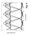
- FIG. 1 shows an example of eye diagrams showing the Associated with receivers 107, 108 and 109 in Fig. 1, respectively 2 the receiver 107, the eye diagram 3 the receiver 108 and the eye diagram according to FIG. 4 is assigned to the receiver 109.
- the differences are obvious and represent different signal qualities, which in turn cause different bit error ratios (BER: bit error ratio).
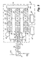
- FIG. 5 shows a block diagram of a test device 10 for Quality assessment of signals, for example in a fully optical Network 101 can be transmitted in any way.
- This test device 10 should, for example, directly behind the optical switching unit 119 (FIG. 1) in the Line 126 inserted.
- the insertion takes place by means of a beam splitter 11, which is a small fraction of that on line 126 Derives carrier beam on the branch 13, e.g. 1% of his performance.
- the branched partial beam passes through a filter 14 that the unwanted Filtered out portions, for example the "yellow” (dotted arrows) carrier beam (corresponding to Fig. 1), so that only the "blue” (solid arrows) Test beam S remains for the test.
- the test device 10 in the embodiment shown comprises one (Further) beam splitter 21 with three outputs 22, 23, 24 for the same sharing Splitting the test beam S, three identically constructed receivers 31, 32, 33, two different transmission elements 41, 42, an attenuator 43, one Logic circuit 62 for controlling the receivers 31, 32, 33 and one Outputs 37, 38, 39 of the receivers 31, 32, 33 downstream Evaluation computer 44.
- a digital signal can be added to this Clock recovery unit 61 come.
- the transmission element 41 is connected between the first output 22 of the beam splitter 21 and the input 34 of the first receiver 31.
- the element 41 is, for example, an abnormal dispersion fiber. This means that the second term of the Taylor series of the propagation constant ⁇ of the carrier frequency responsible for the distortion of the signals is less than zero ( ⁇ 2 ⁇ 0). As a result, the transmission element 41 specifically causes (first) signal distortion of the respective beam S 1 passing through.
- the second transmission element 42 is connected between the second output 23 of the beam splitter 21 and the input 35 of the second receiver 32.
- Element 42 is also a fiber, but with normal dispersion ( ⁇ 2 > 0). Element 42 thus causes a second, different type of signal distortion of the passing beam S 2 . It is preferably required that the total dispersion through the two transmission elements 41 and 42 assume the same values.
- the transmission elements 41, 42 formed as fibers, each have, in addition to the different dispersions described, damping.
- the attenuator 43 is connected between the third output 24 of the beam splitter 21 and the input 36 of the third receiver 33. This weakens the intensity of the respective beam S 0 passing through by an adjustable amount, in particular to the same extent as the two fibers 41, 42. This has the effect that the partial beams S 1 , S 2 , S 0 are largely attenuated to the same extent. This can be exactly ensured if necessary by additional attenuators in the paths of the partial beams S 1 and / or S 2 .
- the attenuator 43 does not cause any dispersion of the signal and thus does not produce any signal distortion.
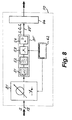
- the identically constructed receivers 31, 32, 33 each have one optoelectric converter 51, in particular a photodiode, optionally one Low pass filter 52, a signal sampler 53 and an analog / digital converter 54. These units are connected in series.
- the low pass filter 52 is not mandatory and can therefore be omitted; also other receiver variations are conceivable.
- the downstream of the receiver outputs 37, 38, 39 Evaluation computer 44 is any digital working computer unit Design type.
- the logic unit 62 is a control device for any Switching through the signal samplers 53. The sampling takes place with digital Signals preferably in synchronism with the signal clock. If this is not available, it can Sampling can also be done asynchronously.
- the test device 10 is both for suitable for digital as well as for analog signals. This will make the Transparency of the communication network 101 with regard to the used Bit rates and the types of modulation are taken into account.
- the test device 10 described so far works as follows:
- the test beam S coming from the filter 14 is divided by the beam splitter 21 into three partial beams S 1 , S 2 , S 0 each with approximately the same intensity and other properties.
- These partial beams pass through the transmission element 41, the transmission element 42 or the attenuator 43.
- they are deliberately differently distorted or not distorted.
- a sequence of assigned electrical intensity signals I 1 , I 2 , I 0 is obtained from the partial beams S 1 , S 2 , S 0 by the receivers 31, 32, 33.
- the partial beams arriving at the inputs 34, 35, 36 are converted into proportional electrical currents or voltages with the aid of the optoelectric converter 51.
- the currents or voltages are sampled in terms of pulses by the signal samplers 53, with each pulse being significantly shorter than the length of a bit in digital signals.
- the integral of the respective charge quantity is then output by the converters 54 at the outputs 37, 38, 39 as digital values of the respective beam intensity I 1 , I 2 , I 0 at the associated sampling times.
- the difference size 2B characterizes the influence of the Test beam S present at the input 15 of the test device 10 Phase changes. These phase changes can be from the modulator of the each associated transmitter (102 in the example of FIG. 1) originate from Non-linearities on the transmission lines already traversed, i.e. the Line 122 (in the example of Fig. 1).
- the sum size 2A supplies Statements about the "susceptibility" of the beam splitter 11 present waveform against dispersion-related distortions further lines to be run through.
- the test device 10 enables thus the determination of test variables on the quality of the transmission signals at any point in an optical transmission network (101), in particular also in the area of switching units 119. With earlier, known methods this was previously not possible.
- test devices 10 can be summarized in whole or in part in such a way that the test quantities accruing from these (10) are managed centrally as data and are evaluable. This can be used, for example, to provide statistical information about gain network behavior, or information about gradual changes. In the event of malfunctions or inadequate behavior, you can go on the targeted comparison of the existing data with the known structure of the Network 101 quickly identify the triggering weak points or errors.
- the invention enables simple and effective evaluation and monitoring of optical networks by anywhere in the Netzes quantitative statements about the quality of the available there Transmission signals can be determined.
- the type of these signals does not matter Role.
- the signals can be analog or digital, with any frequencies.
- the method according to the invention is thus suitable for any optical Participants transparent networks possible. Due to the possibility of Obtaining and comparing data on the signal qualities different parts of the network need to be localized if necessary Errors or weak points in the network are easily possible. This results in a Behavior that far exceeds that of previously known methods with similar Objective goes beyond.
Landscapes
- Physics & Mathematics (AREA)
- Electromagnetism (AREA)
- Engineering & Computer Science (AREA)
- Computer Networks & Wireless Communication (AREA)
- Signal Processing (AREA)
- Optical Communication System (AREA)
- Testing Of Optical Devices Or Fibers (AREA)
Priority Applications (4)
| Application Number | Priority Date | Filing Date | Title |
|---|---|---|---|
| ES99810108T ES2214002T3 (es) | 1999-02-09 | 1999-02-09 | Control de calidad de una señal de transmision optica. |
| EP99810108A EP1028548B1 (fr) | 1999-02-09 | 1999-02-09 | Contrôle de qualité d'un signal optique de transmission |
| DE59908196T DE59908196D1 (de) | 1999-02-09 | 1999-02-09 | Prüfung der Qualität eines optischen Übertragungssignals |
| AT99810108T ATE257296T1 (de) | 1999-02-09 | 1999-02-09 | Prüfung der qualität eines optischen übertragungssignals |
Applications Claiming Priority (1)
| Application Number | Priority Date | Filing Date | Title |
|---|---|---|---|
| EP99810108A EP1028548B1 (fr) | 1999-02-09 | 1999-02-09 | Contrôle de qualité d'un signal optique de transmission |
Publications (2)
| Publication Number | Publication Date |
|---|---|
| EP1028548A1 true EP1028548A1 (fr) | 2000-08-16 |
| EP1028548B1 EP1028548B1 (fr) | 2004-01-02 |
Family
ID=8242668
Family Applications (1)
| Application Number | Title | Priority Date | Filing Date |
|---|---|---|---|
| EP99810108A Expired - Lifetime EP1028548B1 (fr) | 1999-02-09 | 1999-02-09 | Contrôle de qualité d'un signal optique de transmission |
Country Status (4)
| Country | Link |
|---|---|
| EP (1) | EP1028548B1 (fr) |
| AT (1) | ATE257296T1 (fr) |
| DE (1) | DE59908196D1 (fr) |
| ES (1) | ES2214002T3 (fr) |
Citations (5)
| Publication number | Priority date | Publication date | Assignee | Title |
|---|---|---|---|---|
| EP0591961A1 (fr) * | 1992-10-09 | 1994-04-13 | Matsushita Electric Industrial Co., Ltd. | Terminal de communication pour fibres optiques, système de communication par fibres optiques et méthode de réglage de sa longueur d'onde |
| DE19504896A1 (de) * | 1995-02-14 | 1996-08-22 | Siemens Ag | Überwachung der Übertragungsqualität transparenter optischer Netze |
| GB2315938A (en) * | 1996-08-01 | 1998-02-11 | Northern Telecom Ltd | Optical trasmission system fault analysis |
| GB2319419A (en) * | 1996-11-08 | 1998-05-20 | Kokusai Denshin Denwa Co Ltd | An efficient dispersion and loss compensating wavelength division demultiplexer |
| EP0863626A2 (fr) * | 1997-02-05 | 1998-09-09 | Nortel Networks Corporation | Système de transmission optique avec surveillance de la dispersion de modes de polarisation |
-
1999
- 1999-02-09 ES ES99810108T patent/ES2214002T3/es not_active Expired - Lifetime
- 1999-02-09 DE DE59908196T patent/DE59908196D1/de not_active Expired - Lifetime
- 1999-02-09 EP EP99810108A patent/EP1028548B1/fr not_active Expired - Lifetime
- 1999-02-09 AT AT99810108T patent/ATE257296T1/de active
Patent Citations (5)
| Publication number | Priority date | Publication date | Assignee | Title |
|---|---|---|---|---|
| EP0591961A1 (fr) * | 1992-10-09 | 1994-04-13 | Matsushita Electric Industrial Co., Ltd. | Terminal de communication pour fibres optiques, système de communication par fibres optiques et méthode de réglage de sa longueur d'onde |
| DE19504896A1 (de) * | 1995-02-14 | 1996-08-22 | Siemens Ag | Überwachung der Übertragungsqualität transparenter optischer Netze |
| GB2315938A (en) * | 1996-08-01 | 1998-02-11 | Northern Telecom Ltd | Optical trasmission system fault analysis |
| GB2319419A (en) * | 1996-11-08 | 1998-05-20 | Kokusai Denshin Denwa Co Ltd | An efficient dispersion and loss compensating wavelength division demultiplexer |
| EP0863626A2 (fr) * | 1997-02-05 | 1998-09-09 | Nortel Networks Corporation | Système de transmission optique avec surveillance de la dispersion de modes de polarisation |
Also Published As
| Publication number | Publication date |
|---|---|
| DE59908196D1 (de) | 2004-02-05 |
| ATE257296T1 (de) | 2004-01-15 |
| EP1028548B1 (fr) | 2004-01-02 |
| ES2214002T3 (es) | 2004-09-01 |
Similar Documents
| Publication | Publication Date | Title |
|---|---|---|
| DE69736856T2 (de) | Überwachung von nichtlinearen Effekten in einem optischen Übertragungssystem | |
| DE69523106T2 (de) | Vorrichtung und Verfahren zur Kompensation von durch optische Phaserkonjugierung oder andere optische Signalumwandlung verursachter chromatischer Dispersion | |
| DE69811801T2 (de) | Überttragungssystem mit Querphasen- und/oder Eigenphasenmodulationskompensierung | |
| DE60226190T2 (de) | Verfahren und Vorrichtung zur Messung und Bestimmung des optischen Signal-Rauschverhältnis in optischen Netzwerken | |
| DE69935054T2 (de) | Übertragungssystem für ein optisches Zeitmultiplexsignal | |
| DE69834999T2 (de) | Qualitätsüberwachungssystem von optischen Signalen mit verschiedenen Bitraten | |
| DE69736560T2 (de) | Überwachungssystem unter verwendung eines optischen rückhörsignals als testsignal | |
| DE19732568C1 (de) | Verfahren und optisches Übertragungssystem zur Kompensation von Dispersion in optischen Übertragungsstrecken | |
| DE69232475T2 (de) | Optisches Übertragungssystem | |
| DE69806874T2 (de) | Distortionsstrafemessverfahren in optischen Systemen mit Geräuschbelastung | |
| DE69806875T2 (de) | Distortionsstrafemessverfahren in optischen Systemen auf Basis von Signalpegeleinstellung | |
| DE19529376A1 (de) | Optisches TDMA-Ringnetz mit einer zentralen Sende- und Empfangseinrichtung | |
| DE69319970T2 (de) | Verfahren und Vorrichtung zur optischen Übertragung von Solitonen über lange Abstände | |
| DE69531511T2 (de) | System und Verfahren zur Übertragung von optischen Solitonimpulsesignalen durch eine optische Faserstrecke | |
| DE10001388B4 (de) | AWG-(Arrayed Waveguide Grating)-Modul und Vorrichtung zur Überwachung eines Lichtsignals, die dieses verwendet | |
| WO2004034611A1 (fr) | Procede et systeme pour determiner des degradations du signal en presence de distorsions du signal | |
| EP1796295A1 (fr) | Procédé destiné à la détection et à la localisation de perturbations sur un trajet de transmission optique et un système de transmission optique | |
| DE10111497B4 (de) | Verfahren zur Ermittlung der Signalqualität bei optischen Übertragungssystemen | |
| EP1153488A1 (fr) | Procede de surveillance de la qualite de transmission d'un systeme de transmission optique, notamment d'un reseau optique de multiplexage par repartition en longueur d'ondes | |
| DE69912366T2 (de) | Verfahren und Vorrichtung zur Überwachung von dispersiver Wellenenergie zum optimieren der Solitonübertragungsleistung | |
| EP1224754B1 (fr) | Procede et dispositif destines a la surveillance continue d'une liaison de transmission optique | |
| EP1210785B1 (fr) | Dispositif et procede de transmission optique d'informations | |
| EP1063793B1 (fr) | Méthode de mesure de la qualité d'un signal de données optique | |
| EP1028548B1 (fr) | Contrôle de qualité d'un signal optique de transmission | |
| DE10132584B4 (de) | Verfahren und Anordnung zur Ermittlung und Trennung von Einzelkanaleffekten bei der optischen Übertragung eines Wellenlängen-Multiplex(-WDM)-Signals |
Legal Events
| Date | Code | Title | Description |
|---|---|---|---|
| PUAI | Public reference made under article 153(3) epc to a published international application that has entered the european phase |
Free format text: ORIGINAL CODE: 0009012 |
|
| AK | Designated contracting states |
Kind code of ref document: A1 Designated state(s): AT CH DE ES FR GB IT LI NL SE |
|
| AX | Request for extension of the european patent |
Free format text: AL;LT;LV;MK;RO;SI |
|
| AKX | Designation fees paid |
Free format text: AT CH DE ES FR GB IT LI NL SE |
|
| 17P | Request for examination filed |
Effective date: 20010112 |
|
| GRAH | Despatch of communication of intention to grant a patent |
Free format text: ORIGINAL CODE: EPIDOS IGRA |
|
| GRAS | Grant fee paid |
Free format text: ORIGINAL CODE: EPIDOSNIGR3 |
|
| GRAA | (expected) grant |
Free format text: ORIGINAL CODE: 0009210 |
|
| AK | Designated contracting states |
Kind code of ref document: B1 Designated state(s): AT CH DE ES FR GB IT LI NL SE |
|
| PG25 | Lapsed in a contracting state [announced via postgrant information from national office to epo] |
Ref country code: GB Free format text: LAPSE BECAUSE OF FAILURE TO SUBMIT A TRANSLATION OF THE DESCRIPTION OR TO PAY THE FEE WITHIN THE PRESCRIBED TIME-LIMIT Effective date: 20040102 |
|
| REG | Reference to a national code |
Ref country code: GB Ref legal event code: FG4D Free format text: NOT ENGLISH |
|
| REG | Reference to a national code |
Ref country code: CH Ref legal event code: EP |
|
| REF | Corresponds to: |
Ref document number: 59908196 Country of ref document: DE Date of ref document: 20040205 Kind code of ref document: P |
|
| REG | Reference to a national code |
Ref country code: CH Ref legal event code: NV Representative=s name: BOVARD AG PATENTANWAELTE |
|
| REG | Reference to a national code |
Ref country code: SE Ref legal event code: TRGR |
|
| GBT | Gb: translation of ep patent filed (gb section 77(6)(a)/1977) |
Effective date: 20040609 |
|
| REG | Reference to a national code |
Ref country code: ES Ref legal event code: FG2A Ref document number: 2214002 Country of ref document: ES Kind code of ref document: T3 |
|
| ET | Fr: translation filed | ||
| PLBE | No opposition filed within time limit |
Free format text: ORIGINAL CODE: 0009261 |
|
| STAA | Information on the status of an ep patent application or granted ep patent |
Free format text: STATUS: NO OPPOSITION FILED WITHIN TIME LIMIT |
|
| 26N | No opposition filed |
Effective date: 20041005 |
|
| REG | Reference to a national code |
Ref country code: CH Ref legal event code: PFA Free format text: SWISSCOM AG; OSTERMUNDIGENSTRASSE 93; 3000 BERN 29 (CH) -TRANSFER TO- SWISSCOM AG; ALTE TIEFENAUSTRASSE 6 WORBLAUFEN / ITTIGEN; 3050 BERN (CH) |
|
| REG | Reference to a national code |
Ref country code: FR Ref legal event code: CA |
|
| REG | Reference to a national code |
Ref country code: CH Ref legal event code: PFA Owner name: SWISSCOM AG Free format text: SWISSCOM AG#ALTE TIEFENAUSTRASSE 6 WORBLAUFEN / ITTIGEN#3050 BERN (CH) -TRANSFER TO- SWISSCOM AG#ALTE TIEFENAUSTRASSE 6 WORBLAUFEN / ITTIGEN#3050 BERN (CH) |
|
| PGFP | Annual fee paid to national office [announced via postgrant information from national office to epo] |
Ref country code: AT Payment date: 20140212 Year of fee payment: 16 |
|
| PGFP | Annual fee paid to national office [announced via postgrant information from national office to epo] |
Ref country code: IT Payment date: 20150223 Year of fee payment: 17 |
|
| REG | Reference to a national code |
Ref country code: AT Ref legal event code: MM01 Ref document number: 257296 Country of ref document: AT Kind code of ref document: T Effective date: 20150209 |
|
| PG25 | Lapsed in a contracting state [announced via postgrant information from national office to epo] |
Ref country code: AT Free format text: LAPSE BECAUSE OF NON-PAYMENT OF DUE FEES Effective date: 20150209 |
|
| REG | Reference to a national code |
Ref country code: FR Ref legal event code: PLFP Year of fee payment: 18 |
|
| PG25 | Lapsed in a contracting state [announced via postgrant information from national office to epo] |
Ref country code: IT Free format text: LAPSE BECAUSE OF NON-PAYMENT OF DUE FEES Effective date: 20160209 |
|
| REG | Reference to a national code |
Ref country code: FR Ref legal event code: PLFP Year of fee payment: 19 |
|
| REG | Reference to a national code |
Ref country code: FR Ref legal event code: PLFP Year of fee payment: 20 |
|
| PGFP | Annual fee paid to national office [announced via postgrant information from national office to epo] |
Ref country code: NL Payment date: 20180216 Year of fee payment: 20 |
|
| PGFP | Annual fee paid to national office [announced via postgrant information from national office to epo] |
Ref country code: DE Payment date: 20180219 Year of fee payment: 20 Ref country code: CH Payment date: 20180216 Year of fee payment: 20 Ref country code: ES Payment date: 20180327 Year of fee payment: 20 Ref country code: GB Payment date: 20180216 Year of fee payment: 20 |
|
| PGFP | Annual fee paid to national office [announced via postgrant information from national office to epo] |
Ref country code: SE Payment date: 20180227 Year of fee payment: 20 Ref country code: FR Payment date: 20180222 Year of fee payment: 20 |
|
| REG | Reference to a national code |
Ref country code: DE Ref legal event code: R071 Ref document number: 59908196 Country of ref document: DE |
|
| REG | Reference to a national code |
Ref country code: NL Ref legal event code: MK Effective date: 20190208 |
|
| REG | Reference to a national code |
Ref country code: CH Ref legal event code: PL |
|
| REG | Reference to a national code |
Ref country code: GB Ref legal event code: PE20 Expiry date: 20190208 |
|
| REG | Reference to a national code |
Ref country code: SE Ref legal event code: EUG |
|
| PG25 | Lapsed in a contracting state [announced via postgrant information from national office to epo] |
Ref country code: GB Free format text: LAPSE BECAUSE OF EXPIRATION OF PROTECTION Effective date: 20190208 |
|
| REG | Reference to a national code |
Ref country code: ES Ref legal event code: FD2A Effective date: 20201106 |
|
| PG25 | Lapsed in a contracting state [announced via postgrant information from national office to epo] |
Ref country code: ES Free format text: LAPSE BECAUSE OF EXPIRATION OF PROTECTION Effective date: 20190210 |