EP1028610A2 - Flachbaugruppenträger und Leerbaugruppe - Google Patents
Flachbaugruppenträger und Leerbaugruppe Download PDFInfo
- Publication number
- EP1028610A2 EP1028610A2 EP00301012A EP00301012A EP1028610A2 EP 1028610 A2 EP1028610 A2 EP 1028610A2 EP 00301012 A EP00301012 A EP 00301012A EP 00301012 A EP00301012 A EP 00301012A EP 1028610 A2 EP1028610 A2 EP 1028610A2
- Authority
- EP
- European Patent Office
- Prior art keywords
- blank
- retention
- base
- shelf
- unequipped
- Prior art date
- Legal status (The legal status is an assumption and is not a legal conclusion. Google has not performed a legal analysis and makes no representation as to the accuracy of the status listed.)
- Granted
Links
Images




Classifications
-
- H—ELECTRICITY
- H05—ELECTRIC TECHNIQUES NOT OTHERWISE PROVIDED FOR
- H05K—PRINTED CIRCUITS; CASINGS OR CONSTRUCTIONAL DETAILS OF ELECTRIC APPARATUS; MANUFACTURE OF ASSEMBLAGES OF ELECTRICAL COMPONENTS
- H05K7/00—Constructional details common to different types of electric apparatus
- H05K7/20—Modifications to facilitate cooling, ventilating, or heating
- H05K7/20536—Modifications to facilitate cooling, ventilating, or heating for racks or cabinets of standardised dimensions, e.g. electronic racks for aircraft or telecommunication equipment
- H05K7/20554—Forced ventilation of a gaseous coolant
- H05K7/20563—Forced ventilation of a gaseous coolant within sub-racks for removing heat from electronic boards
Definitions
- This invention relates to the packaging of electronic apparatus in an equipment shelf. More particularly, the invention relates to the use of a blank in an unequipped shelf position to equalize airflow back pressure in the shelf, and to retain optical cables provided for future use at the unequipped position.
- Circuit packs circuit boards
- Collections of interconnected circuit packs are often contained in housings referred to as equipment shelves.
- circuit packs are positioned vertically with sufficient spacing to allow for airflow between adjacent packs. Airflow is generated by fans located above or below the shelf, and directed past the packs by enclosing the sides, rear and front of the shelf to be relatively airtight. Air flowing past the boards carries heat away from the electronic devices on the boards, and is then exhausted from the shelf. Ambient air is drawn into the shelf by the fans to refresh and continue the airflow.
- Uniform airflow backpressure is substantially maintained across airflow paths in partially-equipped equipment shelves through use of a novel circuit pack blank for unequipped positions.
- Each blank includes a base for retaining the blank in an unequipped position, and one or more diffuser blades attached to the base to create resistance in an adjacent air plenum.
- the diffuser blade is designed to generate a backpressure in the adjacent air plenum that is substantially equivalent to backpressures generated in air plenums adjacent to the equipped positions.
- two diffuser blades are attached to the base to provide resistance both at the entrance and exit of the adjacent airflow path.
- the blank incorporates a faceplate that supports insertion and removal, and that contains a novel tray for retaining associated cables in position for future use.
- the blank is inserted into an unequipped position in the shelf via an apparatus guide and positioned so that an air plenum is formed between the blank and an adjacent equipped position.
- the diffuser blades attached to the blank effectively reduce the cross-sectional area of this air plenum, so that a backpressure generated by air flow in the air plenum is substantially equivalent to a backpressure generated by air flow in an air plenum adjacent to the equipped position.
- FIG. 1 An illustrative embodiment of the circuit pack apparatus blank 100 is shown in FIG. 1.
- the blank 100 includes a diffuser blade 104 that is perpendicularly attached to a base 102 , in such manner that it faces a lower edge 111 .
- the blank includes a diffuser blade 105 perpendicularly attached to base 102 , in such manner that it faces an upper edge 109.
- diffuser blades 104 and 105 When inserted into an unequipped position in an equipment shelf, diffuser blades 104 and 105 serve to reduce the effective cross-sectional area of an airflow path over the blank 100 , and thereby generate an increased airflow backpressure.
- Diffuser blades 104 and 105 may be integrally molded within base 102 , or attached in a variety of ways well known in the art.
- braces 106 and 113 are added to improve the structural integrity of the diffuser blades 104 and 105 , respectively.
- the base 102 may be effectively constructed in a variety of ways, provided that it can be inserted in the equipment shelf via edges 109 and 111 in a manner equivalent to the insertion of circuit boards in equipped positions.
- the base 102 may simply be formed as a uniform member with rectangular dimensions equivalent to those of the circuit boards.
- the base includes ribs 101 to conserve material and add rigidity. In an alternate embodiment of the invention, material is selectively removed from some of the cells 113 within the ribs 101 to conserve additional material.
- Guide springs 112 are also formed within the base 102 , and provide a mechanism for reducing vibration of the blank when inserted into an unequipped position
- Faceplate 108 is perpendicularly attached to the base 102 , at a front edge 107 of base 102 .
- the faceplate 108 may be attached to the base 102 in a variety of ways.
- the faceplate 108 is integrally molded with the base 102 , and incorporates braces 114 for added rigidity and strength.
- faceplate 108 also includes spring latches 103 , which provide means for securing blank 100 to the unoccupied position in the shelf.
- the latches 103 may be designed in a number of conventional ways
- Faceplate 108 also includes one or more cable trays 110 that are used, for example, to retain optical cables ready for future interconnection with a circuit board that will replace blank 100 in the unequipped position.
- the components of blank 100 can be constructed from a variety of materials.
- an injection molding process may be used to form the blank 100 from a variety of plastic resins.
- ABS Acrylonitrile-Butadine-Styrene
- PC Polycarbonate
- Various blends of ABS and PC may be used to obtain a good balance between strength, cost and ease of manufacture.
- An example of such a blended material is General Electric's C6200 engineering plastic.
- the entire blank 100 may be molded integrally from such a material.
- FIG. 2A illustrates how blank 100 of FIG. 1 functions in an unequipped position in an apparatus shelf 200 to provide airflow backpressure through the position.
- an upper edge 223 and a lower edge 221 of a base 202 locate a blank 202 in apparatus position guides 222 , 220 , respectively.
- Apparatus position guides 222, 220 are affixed to an apparatus shelf frame 232 by one of a variety of conventional methods.
- apparatus position guides 222 , 220 may be produced as an integral stamping in the associated frame surface 234 .
- a fan 224 promotes airflow in a fan plenum 225 interconnected to an apparatus position plenum 226 .
- the apparatus position plenum 226 is effectively enclosed by the blank 202 and a next apparatus position surface 230 along a distance defined by the lower edge 221 and the upper edge 223 .
- a diffuser blade 204 meets the oncoming airflow driven by a fan 224 .
- the diffuser blade 204 reduces the nominal plenum height 229 to an effective plenum height 228 . Although this height is enlarged once the airflow passes diffuser blade 204 , a second diffuser blade 205 located at or near the upper edge presents an additional barrier that again reduces the effective height at the exit from the plenum.
- diffuser blades 204 , 205 are designed to be about 0.950 inches high in an plenum that is nominally 1.575 inches high.
- the effective plenum height 228 is about 0.625 inches.
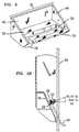
- FIG. 3 further details the structure of an illustrative embodiment of the cable tray 110 of FIG. 1.
- Cable tray 330 includes a retention surface 332 that is designed to be of sufficient area, for example, to hold a connector at the end of an optical cable.
- a retention slot 336 perpendicularly pierces the surface 332 , and is sufficiently wide to permit free passage of, for example, an optical cable having a cordage in the range of 1.6 to 3.0 millimeters.
- An entrance slot 334 of substantially similar width also perpendicularly pierces the surface 332 and the retention slot 336 .
- the entrance slot 336 permits entry of the cable into the retention slot 336 from the front of the faceplate 108 via the entrance slot 334 .
- Walls 338 , 340 , 342 and 344 are perpendicularly provided at the edges of retention surface 332 so that retention surface 332 will continue to retain a cable connector when it is positioned non-horizontally. Because the entrance slot 334 is of sufficient width to pass a cable and not of sufficient width to pass a connector, the connector end of a cable to be retained must be lifted over the wall 338 both for entry into and removal from the cable tray 330 .
- FIG. 3B illustrates a cross-section of the cable tray 330 as attached to faceplate 308 .
- the retention surface 332 is positioned at an inclination angle ⁇ 346 with respect to a horizontal plane perpendicularly piercing faceplate 308 .
- a cable connector 350 is retained by retention surface 332 , with further support, for example, from wall 342 .
- the positioning of retention surface 332 at inclination angle ⁇ 346 allows a cable 348 connected to cable connector 350 to be easily placed in retention slot 336 through faceplate 308 , for example, without substantially bending cable 348 .
- FIGs. 4A and 4B illustrate the operation of springs 112 of FIG. 1.
- base 402 is inserted into apparatus position guide 420 in order to be placed in an unequipped position.
- spring members 460 are compressed by guide walls 462 , and thereby exert a frictional force against the walls 462 that assists in restraining base 402 within guide 420 .
- vibrations in base 402 that would otherwise arise from the forced-air cooling and other forces are substantially reduced.
- FIGs. 5A and 5B illustrate the operation of spring latches 103 of FIG. 1, used to retain the blank 100 in the unequipped position.
- a spring latch 503 includes a spring member 514 attached to a fixed member 502 and an operating lever 504 .
- the fixed member 502 positively attaches the spring latch 503 to the base 102 of FIG. 1.
- the spring member 504 can be compressed by moving the operating lever 504 towards the fixed member 502 , thereby lowering a variable surface 506 so that retention tab 508 may pass horizontally over the variable surface 506 .
- the retention tab 508 is positively attached to the equipment shelf near one of the apparatus position guides 222 , 220 of FIG. 2A as an anchor for retaining the blank 100 of FIG. 1 in its unequipped position.
- the retention tab 508 of FIG. 5A can be brought into direct contact with the variable surface 506 .
- the height of the variable surface 506 increases gradually as it nears the latch stop 510 .
- the retention tab 508 exerts a force on the variable surface 506 .
- This force causes the operating lever 504 to move toward the fixed member 502 , so that the spring member 514 is compressed.
- the variable surface 506 becomes horizontally oriented, enabling the retention tab 508 to continue its horizontal movement until it reaches the latch stop 510 .
- FIG. 5B shows the spring latch 503 and retention tab 508 in position to enable the blank 100 of FIG. 1 to be retained.
- the retention tab 508 passes over the variable surface 506 , it aligns with a holding surface 512 . Since the holding surface 512 is below the adjacent portion of the variable surface 506 , the spring member 504 decompresses to bring the holding surface 512 into contact with the retention tab 508 . Once in contact with the holding surface 512 , the latch stop 510 and an intermediate surface 516 restrict the retention tab 508 from any further horizontal movement.
- the exemplary embodiment of this method described above is but one of a number of alternative embodiments of the invention that will be apparent to those skilled in the art in view of the foregoing description. Accordingly, this description is to be construed as illustrative only, and is for the purpose of teaching those skilled in the art the best mode of carrying out the invention. Various other alternatives can be devised by a worker skilled in the art without departing from the teachings of this invention.
- the blank 100 of FIG. 1 could contain a single diffuser blade 104 .
- the blank 100 could incorporate a raised surface extending across a portion or all of the base 102 with a cross-sectional shape and area substantially similar to the shape and area of diffuser blade 104 .
Landscapes
- Engineering & Computer Science (AREA)
- Aviation & Aerospace Engineering (AREA)
- Physics & Mathematics (AREA)
- Thermal Sciences (AREA)
- Microelectronics & Electronic Packaging (AREA)
- Mounting Of Printed Circuit Boards And The Like (AREA)
- Cooling Or The Like Of Electrical Apparatus (AREA)
- Insertion, Bundling And Securing Of Wires For Electric Apparatuses (AREA)
- Structures Of Non-Positive Displacement Pumps (AREA)
Applications Claiming Priority (2)
| Application Number | Priority Date | Filing Date | Title |
|---|---|---|---|
| US249692 | 1999-02-12 | ||
| US09/249,692 US6309295B1 (en) | 1999-02-12 | 1999-02-12 | Electronic equipment shelf with blank for unequipped position |
Publications (3)
| Publication Number | Publication Date |
|---|---|
| EP1028610A2 true EP1028610A2 (de) | 2000-08-16 |
| EP1028610A3 EP1028610A3 (de) | 2001-05-02 |
| EP1028610B1 EP1028610B1 (de) | 2005-06-15 |
Family
ID=22944580
Family Applications (1)
| Application Number | Title | Priority Date | Filing Date |
|---|---|---|---|
| EP00301012A Expired - Lifetime EP1028610B1 (de) | 1999-02-12 | 2000-02-09 | Flachbaugruppenträger und Leerbaugruppe |
Country Status (5)
| Country | Link |
|---|---|
| US (1) | US6309295B1 (de) |
| EP (1) | EP1028610B1 (de) |
| JP (2) | JP2000236186A (de) |
| CA (1) | CA2298183C (de) |
| DE (1) | DE60020757T2 (de) |
Cited By (1)
| Publication number | Priority date | Publication date | Assignee | Title |
|---|---|---|---|---|
| EP1519644A3 (de) * | 2003-09-24 | 2008-04-09 | Nokia Siemens Networks Gmbh & Co. Kg | Feuerhemmende Methode und Gerät in einer Telekommunikationsanlage |
Families Citing this family (9)
| Publication number | Priority date | Publication date | Assignee | Title |
|---|---|---|---|---|
| US6589308B1 (en) * | 1997-02-28 | 2003-07-08 | Angelo Gianelo | Cabinet for housing a computer workstation |
| US20050095008A1 (en) * | 2003-11-04 | 2005-05-05 | International Business Machines Corporation | Configurator tool for optical networking devices |
| US20050243535A1 (en) * | 2004-04-30 | 2005-11-03 | Shaw Bradley D | Circuit blank for an equipment shelf |
| US20060256522A1 (en) * | 2005-05-10 | 2006-11-16 | Intel Corporation | Method and apparatus to maintain chassis air flow during replacement of a fan module in a fan tray |
| US7595985B2 (en) * | 2006-06-19 | 2009-09-29 | Panduit Corp. | Network cabinet with thermal air flow management |
| CN201041653Y (zh) * | 2007-03-01 | 2008-03-26 | 鸿富锦精密工业(深圳)有限公司 | 电脑装置 |
| US20090061755A1 (en) * | 2007-08-28 | 2009-03-05 | Panduit Corp. | Intake Duct |
| US9839155B2 (en) | 2012-05-16 | 2017-12-05 | Panduit Corp. | Thermal ducting system |
| WO2015122914A1 (en) * | 2014-02-14 | 2015-08-20 | Hewlett-Packard Development Company, L.P. | Controlling impedance of blank cartridges |
Family Cites Families (11)
| Publication number | Priority date | Publication date | Assignee | Title |
|---|---|---|---|---|
| FR2559335B1 (fr) | 1984-02-08 | 1986-05-23 | Telemecanique Electrique | Cellule modulaire de support et de protection de cartes electroniques |
| JPS614484U (ja) * | 1984-06-12 | 1986-01-11 | 三菱電機株式会社 | パツケ−ジシエルフ |
| DE3423047C2 (de) * | 1984-06-22 | 1986-06-19 | Heidelberger Druckmaschinen Ag, 6900 Heidelberg | Filtereinrichtung an elektrischen Schaltschränken, Elektronikgehäusen oder ähnlichen, während des Betriebes zu belüftenden, staub- und fremdkörperfrei zu haltenden Geräten |
| JPH0394495A (ja) * | 1989-09-06 | 1991-04-19 | Mitsubishi Electric Corp | シャッター付ダミーカード |
| JP2934493B2 (ja) * | 1990-10-24 | 1999-08-16 | 株式会社日立製作所 | 電子機器の冷却装置 |
| JPH062781U (ja) * | 1992-06-19 | 1994-01-14 | 安藤電気株式会社 | プリント基板間の未実装空間に挿入される通風抵抗板 |
| JPH0766577A (ja) * | 1993-08-26 | 1995-03-10 | Fujitsu Ltd | シェルフの冷却構造 |
| JPH07202464A (ja) * | 1993-12-28 | 1995-08-04 | Toshiba Corp | 電子機器装置並びに電子機器装置用冷却方法及びファン装置 |
| US5563768A (en) * | 1995-08-31 | 1996-10-08 | At&T Global Information Solutions Company | Heat source cooling apparatus and method utilizing mechanism for dividing a flow of cooling fluid |
| US5707282A (en) | 1996-02-28 | 1998-01-13 | Hewlett-Packard Company | Fan diffuser |
| DE29619482U1 (de) | 1996-11-11 | 1997-12-11 | Siemens AG, 80333 München | Baugruppenträger mit Luftkühlung für Leiterplatten |
-
1999
- 1999-02-12 US US09/249,692 patent/US6309295B1/en not_active Expired - Fee Related
-
2000
- 2000-02-07 CA CA002298183A patent/CA2298183C/en not_active Expired - Fee Related
- 2000-02-09 EP EP00301012A patent/EP1028610B1/de not_active Expired - Lifetime
- 2000-02-09 DE DE60020757T patent/DE60020757T2/de not_active Expired - Fee Related
- 2000-02-14 JP JP2000035788A patent/JP2000236186A/ja active Pending
-
2007
- 2007-11-14 JP JP2007295049A patent/JP4603032B2/ja not_active Expired - Fee Related
Cited By (1)
| Publication number | Priority date | Publication date | Assignee | Title |
|---|---|---|---|---|
| EP1519644A3 (de) * | 2003-09-24 | 2008-04-09 | Nokia Siemens Networks Gmbh & Co. Kg | Feuerhemmende Methode und Gerät in einer Telekommunikationsanlage |
Also Published As
| Publication number | Publication date |
|---|---|
| DE60020757D1 (de) | 2005-07-21 |
| EP1028610A3 (de) | 2001-05-02 |
| JP2000236186A (ja) | 2000-08-29 |
| CA2298183A1 (en) | 2000-08-12 |
| CA2298183C (en) | 2003-04-15 |
| JP2008091939A (ja) | 2008-04-17 |
| JP4603032B2 (ja) | 2010-12-22 |
| US6309295B1 (en) | 2001-10-30 |
| EP1028610B1 (de) | 2005-06-15 |
| DE60020757T2 (de) | 2006-05-18 |
Similar Documents
| Publication | Publication Date | Title |
|---|---|---|
| US4774631A (en) | Cooling structure of electronic equipment rack | |
| JP4603032B2 (ja) | 回路パック用ブランク | |
| US7911785B2 (en) | Rack mounted computer system including chassis retainer | |
| US7042717B2 (en) | Data storage system with a removable backplane having a array of disk drives | |
| US7215552B2 (en) | Airflow redistribution device | |
| US7236370B2 (en) | Computer rack with cluster modules | |
| US7522415B2 (en) | Mounting assembly for fan | |
| EP2146563B1 (de) | Luftstrom-/Kühlungslösung für Fahrgestell | |
| US5497288A (en) | Apparatus for tilted serial cooling in an electronic system | |
| JP6088078B2 (ja) | 熱を放散するための改善された通気を有する電子装置のエンクロージャ | |
| US20110014861A1 (en) | Air duct assembly and heat dissipating assembly | |
| US8630087B1 (en) | Airflow system, cable access system, and cable management system based on midplane having holes, side access of chassis, and card configuration | |
| US5923532A (en) | Lanced card guide | |
| JPWO1986003089A1 (ja) | 電子装置用架の冷却構造 | |
| WO2006129350A1 (ja) | 通信装置、情報処理装置及び外線ケーブルの接続方法 | |
| JPH03159300A (ja) | 電子部品を冷却するための装置 | |
| WO2002063627A2 (en) | Memory storage device rack having vented rails | |
| CN102129273A (zh) | 电脑系统 | |
| EP0886463B1 (de) | Kompaktes Kühlgerät für Baugruppen in einem Käfig | |
| US20100172740A1 (en) | Heat dissipating device | |
| CN102023683A (zh) | 服务器机柜 | |
| US20160231791A1 (en) | Electronic device with cooling facility | |
| US20030117782A1 (en) | Electronic circuits | |
| US20130170135A1 (en) | Airflow guide member and electronic device having the same | |
| US5424914A (en) | Through backplane impingement cooling apparatus |
Legal Events
| Date | Code | Title | Description |
|---|---|---|---|
| PUAI | Public reference made under article 153(3) epc to a published international application that has entered the european phase |
Free format text: ORIGINAL CODE: 0009012 |
|
| AK | Designated contracting states |
Kind code of ref document: A2 Designated state(s): DE FR IT |
|
| AX | Request for extension of the european patent |
Free format text: AL;LT;LV;MK;RO;SI |
|
| PUAL | Search report despatched |
Free format text: ORIGINAL CODE: 0009013 |
|
| AK | Designated contracting states |
Kind code of ref document: A3 Designated state(s): AT BE CH CY DE DK ES FI FR GB GR IE IT LI LU MC NL PT SE |
|
| AX | Request for extension of the european patent |
Free format text: AL;LT;LV;MK;RO;SI |
|
| RIC1 | Information provided on ipc code assigned before grant |
Free format text: 7H 05K 7/14 A, 7H 05K 7/20 B |
|
| 17P | Request for examination filed |
Effective date: 20011018 |
|
| AKX | Designation fees paid |
Free format text: DE FR IT |
|
| 17Q | First examination report despatched |
Effective date: 20040817 |
|
| GRAP | Despatch of communication of intention to grant a patent |
Free format text: ORIGINAL CODE: EPIDOSNIGR1 |
|
| GRAS | Grant fee paid |
Free format text: ORIGINAL CODE: EPIDOSNIGR3 |
|
| GRAA | (expected) grant |
Free format text: ORIGINAL CODE: 0009210 |
|
| AK | Designated contracting states |
Kind code of ref document: B1 Designated state(s): DE FR IT |
|
| REF | Corresponds to: |
Ref document number: 60020757 Country of ref document: DE Date of ref document: 20050721 Kind code of ref document: P |
|
| ET | Fr: translation filed | ||
| PLBE | No opposition filed within time limit |
Free format text: ORIGINAL CODE: 0009261 |
|
| STAA | Information on the status of an ep patent application or granted ep patent |
Free format text: STATUS: NO OPPOSITION FILED WITHIN TIME LIMIT |
|
| 26N | No opposition filed |
Effective date: 20060316 |
|
| PGFP | Annual fee paid to national office [announced via postgrant information from national office to epo] |
Ref country code: DE Payment date: 20090219 Year of fee payment: 10 |
|
| PGFP | Annual fee paid to national office [announced via postgrant information from national office to epo] |
Ref country code: IT Payment date: 20090223 Year of fee payment: 10 |
|
| PGFP | Annual fee paid to national office [announced via postgrant information from national office to epo] |
Ref country code: FR Payment date: 20090213 Year of fee payment: 10 |
|
| REG | Reference to a national code |
Ref country code: FR Ref legal event code: ST Effective date: 20101029 |
|
| PG25 | Lapsed in a contracting state [announced via postgrant information from national office to epo] |
Ref country code: FR Free format text: LAPSE BECAUSE OF NON-PAYMENT OF DUE FEES Effective date: 20100301 |
|
| PG25 | Lapsed in a contracting state [announced via postgrant information from national office to epo] |
Ref country code: DE Free format text: LAPSE BECAUSE OF NON-PAYMENT OF DUE FEES Effective date: 20100901 |
|
| PG25 | Lapsed in a contracting state [announced via postgrant information from national office to epo] |
Ref country code: IT Free format text: LAPSE BECAUSE OF NON-PAYMENT OF DUE FEES Effective date: 20100209 |