EP1029202B1 - Regenerativer wärmetauscher - Google Patents
Regenerativer wärmetauscher Download PDFInfo
- Publication number
- EP1029202B1 EP1029202B1 EP97912129A EP97912129A EP1029202B1 EP 1029202 B1 EP1029202 B1 EP 1029202B1 EP 97912129 A EP97912129 A EP 97912129A EP 97912129 A EP97912129 A EP 97912129A EP 1029202 B1 EP1029202 B1 EP 1029202B1
- Authority
- EP
- European Patent Office
- Prior art keywords
- heat exchanger
- drum
- exchanger according
- bearing
- counterflow heat
- Prior art date
- Legal status (The legal status is an assumption and is not a legal conclusion. Google has not performed a legal analysis and makes no representation as to the accuracy of the status listed.)
- Expired - Lifetime
Links
- 230000001172 regenerating effect Effects 0.000 title claims description 26
- 238000007789 sealing Methods 0.000 claims description 23
- 238000006073 displacement reaction Methods 0.000 claims description 3
- 238000009423 ventilation Methods 0.000 abstract description 16
- XLYOFNOQVPJJNP-UHFFFAOYSA-N water Substances O XLYOFNOQVPJJNP-UHFFFAOYSA-N 0.000 description 17
- 239000011521 glass Substances 0.000 description 13
- 238000010276 construction Methods 0.000 description 12
- 238000003860 storage Methods 0.000 description 10
- 239000004744 fabric Substances 0.000 description 8
- 238000013461 design Methods 0.000 description 7
- 229920003023 plastic Polymers 0.000 description 7
- 229920001296 polysiloxane Polymers 0.000 description 7
- 238000011084 recovery Methods 0.000 description 7
- 239000006096 absorbing agent Substances 0.000 description 6
- 238000009434 installation Methods 0.000 description 6
- 239000004033 plastic Substances 0.000 description 6
- 238000009413 insulation Methods 0.000 description 5
- 238000005192 partition Methods 0.000 description 5
- UXVMQQNJUSDDNG-UHFFFAOYSA-L Calcium chloride Chemical compound [Cl-].[Cl-].[Ca+2] UXVMQQNJUSDDNG-UHFFFAOYSA-L 0.000 description 4
- 238000004140 cleaning Methods 0.000 description 4
- 238000001816 cooling Methods 0.000 description 4
- 230000000694 effects Effects 0.000 description 4
- 238000001704 evaporation Methods 0.000 description 4
- 238000007493 shaping process Methods 0.000 description 4
- 229920000742 Cotton Polymers 0.000 description 3
- VVQNEPGJFQJSBK-UHFFFAOYSA-N Methyl methacrylate Chemical compound COC(=O)C(C)=C VVQNEPGJFQJSBK-UHFFFAOYSA-N 0.000 description 3
- CBENFWSGALASAD-UHFFFAOYSA-N Ozone Chemical compound [O-][O+]=O CBENFWSGALASAD-UHFFFAOYSA-N 0.000 description 3
- 229920005372 Plexiglas® Polymers 0.000 description 3
- 229910052782 aluminium Inorganic materials 0.000 description 3
- 230000015572 biosynthetic process Effects 0.000 description 3
- 238000009833 condensation Methods 0.000 description 3
- 230000005494 condensation Effects 0.000 description 3
- 230000008020 evaporation Effects 0.000 description 3
- 238000010438 heat treatment Methods 0.000 description 3
- 238000012423 maintenance Methods 0.000 description 3
- 230000009467 reduction Effects 0.000 description 3
- 230000003068 static effect Effects 0.000 description 3
- 229910000831 Steel Inorganic materials 0.000 description 2
- XAGFODPZIPBFFR-UHFFFAOYSA-N aluminium Chemical compound [Al] XAGFODPZIPBFFR-UHFFFAOYSA-N 0.000 description 2
- 238000012937 correction Methods 0.000 description 2
- 230000001419 dependent effect Effects 0.000 description 2
- 239000000428 dust Substances 0.000 description 2
- 230000005611 electricity Effects 0.000 description 2
- 238000002955 isolation Methods 0.000 description 2
- 238000004519 manufacturing process Methods 0.000 description 2
- 239000000463 material Substances 0.000 description 2
- 229920003229 poly(methyl methacrylate) Polymers 0.000 description 2
- 239000004926 polymethyl methacrylate Substances 0.000 description 2
- 230000005855 radiation Effects 0.000 description 2
- 239000000243 solution Substances 0.000 description 2
- 125000006850 spacer group Chemical group 0.000 description 2
- 239000010959 steel Substances 0.000 description 2
- 239000000725 suspension Substances 0.000 description 2
- 238000012549 training Methods 0.000 description 2
- 238000012546 transfer Methods 0.000 description 2
- 230000007704 transition Effects 0.000 description 2
- 241000894006 Bacteria Species 0.000 description 1
- 235000008733 Citrus aurantifolia Nutrition 0.000 description 1
- 241000238631 Hexapoda Species 0.000 description 1
- 229920002292 Nylon 6 Polymers 0.000 description 1
- -1 Polyethylene Polymers 0.000 description 1
- 239000004698 Polyethylene Substances 0.000 description 1
- 229920002323 Silicone foam Polymers 0.000 description 1
- 235000011941 Tilia x europaea Nutrition 0.000 description 1
- 230000002745 absorbent Effects 0.000 description 1
- 239000002250 absorbent Substances 0.000 description 1
- 238000010521 absorption reaction Methods 0.000 description 1
- NIXOWILDQLNWCW-UHFFFAOYSA-N acrylic acid group Chemical group C(C=C)(=O)O NIXOWILDQLNWCW-UHFFFAOYSA-N 0.000 description 1
- 238000013459 approach Methods 0.000 description 1
- 229910001628 calcium chloride Inorganic materials 0.000 description 1
- 239000001110 calcium chloride Substances 0.000 description 1
- 230000000295 complement effect Effects 0.000 description 1
- 150000001875 compounds Chemical class 0.000 description 1
- 239000013078 crystal Substances 0.000 description 1
- 238000013016 damping Methods 0.000 description 1
- 239000003599 detergent Substances 0.000 description 1
- 230000003670 easy-to-clean Effects 0.000 description 1
- 238000005265 energy consumption Methods 0.000 description 1
- 210000001061 forehead Anatomy 0.000 description 1
- 239000003205 fragrance Substances 0.000 description 1
- 230000005484 gravity Effects 0.000 description 1
- 239000004519 grease Substances 0.000 description 1
- 239000004571 lime Substances 0.000 description 1
- 238000005259 measurement Methods 0.000 description 1
- 239000012528 membrane Substances 0.000 description 1
- 238000012544 monitoring process Methods 0.000 description 1
- 230000007935 neutral effect Effects 0.000 description 1
- 230000003287 optical effect Effects 0.000 description 1
- 230000002093 peripheral effect Effects 0.000 description 1
- 229920000573 polyethylene Polymers 0.000 description 1
- 230000002028 premature Effects 0.000 description 1
- 230000008929 regeneration Effects 0.000 description 1
- 238000011069 regeneration method Methods 0.000 description 1
- 238000005096 rolling process Methods 0.000 description 1
- 239000005336 safety glass Substances 0.000 description 1
- 150000003839 salts Chemical class 0.000 description 1
- 238000000926 separation method Methods 0.000 description 1
- 239000013514 silicone foam Substances 0.000 description 1
- 238000001179 sorption measurement Methods 0.000 description 1
- 239000012086 standard solution Substances 0.000 description 1
- 239000008399 tap water Substances 0.000 description 1
- 235000020679 tap water Nutrition 0.000 description 1
- 239000012780 transparent material Substances 0.000 description 1
- 238000011144 upstream manufacturing Methods 0.000 description 1
- 235000021419 vinegar Nutrition 0.000 description 1
- 239000000052 vinegar Substances 0.000 description 1
Images


Classifications
-
- F—MECHANICAL ENGINEERING; LIGHTING; HEATING; WEAPONS; BLASTING
- F24—HEATING; RANGES; VENTILATING
- F24F—AIR-CONDITIONING; AIR-HUMIDIFICATION; VENTILATION; USE OF AIR CURRENTS FOR SCREENING
- F24F12/00—Use of energy recovery systems in air conditioning, ventilation or screening
- F24F12/001—Use of energy recovery systems in air conditioning, ventilation or screening with heat-exchange between supplied and exhausted air
- F24F12/006—Use of energy recovery systems in air conditioning, ventilation or screening with heat-exchange between supplied and exhausted air using an air-to-air heat exchanger
-
- F—MECHANICAL ENGINEERING; LIGHTING; HEATING; WEAPONS; BLASTING
- F28—HEAT EXCHANGE IN GENERAL
- F28D—HEAT-EXCHANGE APPARATUS, NOT PROVIDED FOR IN ANOTHER SUBCLASS, IN WHICH THE HEAT-EXCHANGE MEDIA DO NOT COME INTO DIRECT CONTACT
- F28D19/00—Regenerative heat-exchange apparatus in which the intermediate heat-transfer medium or body is moved successively into contact with each heat-exchange medium
- F28D19/04—Regenerative heat-exchange apparatus in which the intermediate heat-transfer medium or body is moved successively into contact with each heat-exchange medium using rigid bodies, e.g. mounted on a movable carrier
- F28D19/045—Regenerative heat-exchange apparatus in which the intermediate heat-transfer medium or body is moved successively into contact with each heat-exchange medium using rigid bodies, e.g. mounted on a movable carrier with radial flow through the intermediate heat-transfer medium
-
- F—MECHANICAL ENGINEERING; LIGHTING; HEATING; WEAPONS; BLASTING
- F24—HEATING; RANGES; VENTILATING
- F24F—AIR-CONDITIONING; AIR-HUMIDIFICATION; VENTILATION; USE OF AIR CURRENTS FOR SCREENING
- F24F2203/00—Devices or apparatus used for air treatment
- F24F2203/10—Rotary wheel
- F24F2203/1004—Bearings or driving means
-
- Y—GENERAL TAGGING OF NEW TECHNOLOGICAL DEVELOPMENTS; GENERAL TAGGING OF CROSS-SECTIONAL TECHNOLOGIES SPANNING OVER SEVERAL SECTIONS OF THE IPC; TECHNICAL SUBJECTS COVERED BY FORMER USPC CROSS-REFERENCE ART COLLECTIONS [XRACs] AND DIGESTS
- Y02—TECHNOLOGIES OR APPLICATIONS FOR MITIGATION OR ADAPTATION AGAINST CLIMATE CHANGE
- Y02B—CLIMATE CHANGE MITIGATION TECHNOLOGIES RELATED TO BUILDINGS, e.g. HOUSING, HOUSE APPLIANCES OR RELATED END-USER APPLICATIONS
- Y02B30/00—Energy efficient heating, ventilation or air conditioning [HVAC]
- Y02B30/56—Heat recovery units
Definitions
- the ventilation energy share in buildings is according to the new thermal insulation regulation 1995 up to 70% of the heating energy. You could use the ventilation heat effective recovery, approx. 15 in the FRG could be Save millions of tons of heating oil.
- the aim of this invention was to provide a very high ventilation system To develop heat recovery, which is largely by everyone can be used to enable the above savings.
- this system should be all or most ventilation-related Can meet user requests, i.e. for winter operation the Fresh air warm, in summer the fresh air should be cooled in the room can be introduced. The fresh air should also be sufficient Mass to be filtered. In winter there should also be the possibility bring the fresh air humidified into the room, but not in the Summer.
- the device should cost little, be invisible, as small as possible and maintenance-free be, have a long lifespan, be inaudible, no train make and use little electricity.
- the drum drive torque is so low that the swirl contained in the downstream of the fresh air taxi fan this torque easily delivers.
- This twist can be used in three ways, initially to overcome the frictional torque. Continue to overcome the Exhaust air flow torque: If the exhaust air passes through the heat exchanger, a twist is applied to it according to the rotation speed of the heat exchanger. This twist imprints the rotation from. Ultimately, to automatically adjust the rotor speed to the Air flow: Starting from a certain operating condition, the through the instantaneous air volume and a certain rotation speed is marked, i.e. state of equilibrium between driving and braking moment, when both air volumes are increased a higher drive torque for the fresh air fan is required.
- the service life is primarily due to the bearing oil of the plain bearings of fans temporarily limited. This is why these camps get so cold kept as possible and heating by the engine is caused by high Efficiency kept low. Because anyway after about 10 - 15 years here Maintenance work is necessary, and expensive customer service can be avoided the impeller and storage are made into a pluggable unit, which only through the permanent magnets present in this unit anyway be axially fixed by the stator of the external rotor motor. This unit can then be used without tools within seconds be changed by the user. It is also easy to do that The race and the impeller itself are easy to clean.
- the central warehouse preferably a small ball bearing, can also be from Users themselves can be easily changed. The service life of this camp is because of the very low load and the low temperatures in the Order of 30 years. The central warehouse remains with the necessary Clean the heat exchanger in the crossbar so that this Bearing is never exposed to moisture.
- an additional Noise source can be dispensed with, especially at low Noise levels can be dominant.
- the heat exchanger itself ultimately works through the two Perforated sheets and the heat-transmitting network as an effective sound absorber.
- there is still some space in the interior of the drum can be filled with sound absorbers, of course with partial task of transparency.
- the device After removing the heat exchanger, it can be placed in a bathtub cold water and detergent easily cleaned by rolling back and forth become. Every six months an intensive cleaning with salt water in be carried out in the same way.
- the device is due to the possibility of installation in the window pane accessible from all sides and thus fully cleanable, even the wheels and the race.
- the transparent fan holders made of acrylic glass
- the bacteria and mushroom-killing effect of the UV component of sunlight on the heat exchanger made available.
- the heat exchanger via two axial high-voltage wires in the room-side exhaust air area Ozone can be supplied. This frees the heat exchanger fabric effective from odorants and gets directly into the outside air. There The heat exchanger moves under the wires, it becomes all over Surface cleaned.
- the local ozone concentration can be very high are high while the concentration in the exhaust air itself is low can. No ozone gets into the room air itself.
- the cleaning and maintenance work can be done by magnetic fixation all elements can be carried out practically without tools.
- evaporative cooling is used in conjunction with the capillary effect used by tissues for water transport.
- the exhaust air through a damp cotton fabric before it gets into the heat exchanger with a structure similar to the heat exchanger network. A bandage has proven to be useful here. Approximately four layers are sufficient for approx. 98% air humidification.
- This fabric cools the exhaust air practically to the cooling limit temperature from.
- the cold exhaust air then enters the heat exchanger and cools this too.
- the fresh air is then almost as you pass cooled down to this temperature without additional moisture take. On average, the fresh air is about 6 ° C colder than the exhaust air into the room.
- the tissue is supplied with water as follows:
- the U-shaped channels are closed at their front ends.
- the U channels are contained in a flat horizontal frame such that the upper frame surface is flush with the open U channels, the ends of the U channels still open about 10 mm into the frame.
- a suitably cut multilayer can now be placed on this frame Cotton fabrics are laid flat.
- the advantage of the arrangement described is that the cooling down to the small additional pressure loss can be operated without external energy can and gets by with the minimal amounts of water required and no further regulation is necessary. It is also advantageous that for the Water supply because of the small amounts of a hose of less can be used as 1 mm clear width, which is almost invisible and can be installed quickly.
- the construction is preferably made of transparent Plastic.
- the evaporation frame described is preferably made folded, so that the required flow cross-section with a small overall width is obtained.
- the device must work properly in a temperature range from -30 ° C to +40 ° C work, parts of the device regardless of the outside temperature are each at room temperature level while at the same time other parts assume outside temperature.
- the device Due to user acceptance and the installation of window panes, the device must be transparent, small and quiet, yet still have high efficiency and high ventilation performance (size approx. 380 mm with a depth of 200 mm on the room side and 80 - 200 m 3 / h fresh air at ⁇ 90%).
- a seal namely that between the rotor and the mounting ring, is special critical, since the amount of air that flows through here is not due to the heat exchange participates. If 1% of the air volume flows through here, it will decrease Efficiency is already around 1%, i.e. H. the actual heat transfer quality must be 91% instead of 90%. This in turn means approx. 10% larger heat exchanger. Since there are also other efficiency reductions Factors play in, the last value is even higher. This would hardly matter with a less efficient device, but becomes essential with a highly efficient device. With a highly efficient Device it doesn't matter for ventilation energy consumption, whether there is much or little or no ventilation, d. H. it is with such Device no longer controls air volume or air quality monitoring necessary. In the case of a low-efficiency device, however, there are such regulations still useful and necessary. Certain parts of the device, namely all surfaces on the room side are the room temperature and room humidity exposed. The inside surfaces of the device are all the outside air conditions exposed.
- the Measures taken can be divided into two groups.
- the swirl which the fresh air fan is of axial design is used naturally imprints the air.
- This air rotation is caused by the heat exchanger network slowed down because it acts like a turbine grid itself.
- the Angular momentum moves the heat exchanger.
- This principle can be of course also on other regenerative heat exchangers with rotary drive transferred if a corresponding smooth-running storage is provided.
- This principle can also be used with completely passive heat exchanger elements be carried out when generated by a static swirl Measure the air a peripheral component is given. Further advantageous is with this rotary drive that the speed of rotation is automatic adapts to the air volume. Since the drive torque is very small, there is a risk that z. B. insects, which in the lateral sealing gap pulled, which could bring the drive to a standstill.
- the heat exchanger is localized at the top and bottom Air volumes applied.
- the reason for this is that, for example the fresh air flow near the windscreen has a higher dynamic Pressure component has as near the mounting ring. That is why the heat exchanger depending on the axial position with different air volumes applied. Something similar happens on the exhaust side.
- By appropriate Training of the longitudinal beams can be achieved that the Air volumes in an axial position for fresh air and exhaust air are the same size are without losing heat exchanger surface.
- the exact The design of the crossbeams is only possible after appropriate measurement of local axial efficiency possible.
- the disc warps due to the temperature differences (bimetal effect). Glass, in contrast to a conceivable plastic, has a 5-fold higher thermal conductivity and about 7 times less thermal expansion, which results in 35 times less warping. A Warping would reduce the critical sealing gap and the drum Let it touch, as the drum is axially fixed from the disc side from done.
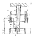
- the magnetic bearing is at the front of the open end of the drum arranged practically axially and can still absorb radial forces. This is achieved in that the arranged in the mounting ring Magnetic counter system made about 1 mm smaller in diameter becomes.
- the drum can only tilt within the central bearing run a cone with the cone tip in the central bearing lies. With the correct dimensioning of the sealing gap and the mentioned Diameter difference, stable storage is achieved in that when the drum tilts down, the magnets on the top approach and thus increase the braking forces and thus the tilting movement counteract. The same in the opposite sense takes place on the opposite side (below). Remove with the same tilting movement the magnets and the counteracting total torque around the central one The pivot point is further enlarged.
- the magnetic one works Counter bearing in the lower area reduces the load capacity, but the whole Magnetic bearings are considerably stiffer and less sensitive to them temperature-dependent changes in magnetic properties (about 10%).
- the operating load must also be taken into account the rotor weight (here 27 N) and the variable pressures in the Supply air and exhaust air chambers combined (here 0 - 9 N). Among all of these Under certain circumstances the storage must be sufficiently safe and the critical one Sealing gap may only change by approx. 0.1 mm.
- a second outer perforated plate which in thermal contact with the face rings and a first Perforated sheet, on which the heat exchanger is wound, and the thermal and is mechanically decoupled from the end rings.
- the primary task of the second perforated plate is that front rings to keep at room temperature to prevent condensation and to prevent ice formation on the magnetic bearing.
- the Perforated sheet acts as a relatively good heat exchanger and is located practically at room temperature.
- the associated rings and the forehead side magnetic bearings are also kept at room temperature. If the stationary part of the magnetic bearing is also removed from the mounting ring thermal insulation, there are no longer any problems caused by Condensation and ice formation could occur.
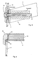
- the outer perforated sheet is in thermal contact with the end rings, it also has load-bearing Function, in contrast to the first inner perforated plate. This must be kept isolated from the rings on the front, because otherwise the rings an average temperature between room temperature and outside temperature would set. This thermal insulation happens over yielding silicone inserts, which also the different length changes balance between inner and outer perforated sheet can.
- the glass pane is insulated similarly for the same reasons held. The glass pane itself could ideally be a vacuum insulated Be a unit if available.
- the mounting ring to which the longitudinal beams must be attached therefore provide grooves similar to thread grooves on the inner circumference.
- the longitudinal beams are cut out of a cylinder jacket, which is also in a corresponding axial position on the circumference and at one end face is provided with such grooves.
- the crossbeam will again provided with such grooves on the end face and drilled directly centrally.
- the central deep groove ball bearing is firmly connected to a steel axis, which is loosely inserted through the crossbeam hole and at the other end carries a thread, which is also in a thread-carrying plastic piece is axially fixed.
- the plastic piece is in turn on the crossbar fixed.
- the ball bearing moves away from the other side of the crossbar. This is necessary because at the same time the longitudinal beams become shorter outer perforated plate remains unchanged in length (room temperature) and therefore the sealing gap would become smaller. Due to the axial displacement this is compensated for by the ball bearing.
- the ball bearing sits with its outer ring firmly in one part, which is also a thread on the outside carries and is provided with an axial stop.
- the partition is fixed magnetically and designed to be removable at the bottom.
- the all-round magnetic fixation also makes it easy to permanently install the partition wall.
- the magnetic strips are arranged so that they are sealing can slide on each other. With extreme noise requirements, the Use the interior even further for sound absorbing measures, because on the inflow of fans is not taken into account very much got to.
- the honeycomb rectifier arranged in front of the intake openings make this possible.
- the basic idea here is not to let noise arise in the first place, because existing noise can only be removed with voluminous effort can.
- the main source of noise is the ventilator.
- the first measure is therefore the usual one leave short and small fan design.
- the current needs space to be able to organize itself gently. Therefore one will be sufficient large inlet nozzle provided, which without radius jumps the flow accelerates to the impeller inflow velocity.
- Good results are already achieved with an elliptically shaped nozzle achieved that starts at about 1.37 times the impeller diameter and one Depth of about 0.24 times the impeller diameter.
- the values and the Form are only meant as an example, about an idea of the To give space.
- a honeycomb flow straightener is installed upstream of the nozzle of about 3 mm honeycomb depth and diameter. This is hemispherical or designed as a basket to do its job perform low flow velocities and pressure drops can.
- the basket is sunk in one around the nozzle Groove inserted, magnetically fixed, so that the air without threshold of the nozzle can flow in.
- Behind the impeller begins a diffuser.
- the inlet consists of a transition radius of approximately impeller diameter and flows continuously into a straight diffuser. The large transition radius prevents premature separation of the flow by the fact that the Flow direction is not changed abruptly.
- a short tube is connected as an impact diffuser, which in the exhaust air outlet also sucking in the exhaust air prevented.
- This tube is also magnetically fixed.
- the entire length Such a fan is about 1.5 times the impeller diameter.
- the struts that keep the fan motor in the race are far away from the impeller at the end of the diffuser inlet.
- the fan drive provided with a counterweight, which allows the unit in their center of gravity, which enables the struts to be attached to be very thin.
- the struts will be at the same time used as a power supply for the low voltage.
- the drive unit itself consists of an impeller, bearing and motor stator Electronics, bearing tube, counterweight, bearing tube housing, vibration decoupling and adjustment device.
- the bearing (one-piece plain bearing) forms a unit with the impeller, which is held together with a locking ring.
- This unit can be inserted axially into the bearing tube and in principle forms a plain bearing Bearings.
- the Motor stator is also attached to the bearing tube and certain points fixed with silicone. This is intended to ensure that if necessary, a new motor stator can be easily installed if necessary.
- the stator gets its current from the struts via plug connections.
- the bearing tube provided with a counterweight at the end, is supported by two axially, radially and torsionally elastic silicone washers, which are symmetrical are arranged to focus.
- the silicone disks themselves can be moved radially in the drive housing stored. Via a thread and a force-transmitting spacer their position can be fixed by axial clamping.
- This construction allows all possible corrections (radial and angular corrections) with a single screw.
- Air is preferably provided that the heat exchanger in a calcium chloride solution is brought so that after removal from it with Calcium chloride is soaked, which is able to absorb water vapor.
- the moisture recovery can be done by choosing the concentration of the Calcium chloride solution can be adjusted.
- Regenerative countercurrent heat exchanger for gaseous media in particular air heat exchanger for the ventilation of rooms in buildings, with a heat exchanger drum through which the heat-emitting and the heat-absorbing gaseous medium flow in alternating sequence, the active surface of which consists of a multi-layer network, at least one fan supplying and supply air generates an exhaust air stream, and wherein the heat exchanger drum essentially forms an outer fixed device boundary.
- Only non-contact gap seals are expediently used as sealing elements.
- An outer perforated plate expediently has thermal contact with the end rings in order to keep them at about room temperature.
- a relatively "cold" inner perforated plate is expediently kept thermally insulated.
- the front central bearing expediently remains in the crossmember after the drum has been removed.
- an end closure of the drum consists of a transparent material, preferably glass.
- a transparent material preferably glass.
- it remains captive on one of the parts to be separated.
- highly elastic intermediate elements are expediently used for the glass pane / central bearing mount or outer rings / inner perforated plate or pane mounting ring / fan holder or fan holder / fan bearing ring.
- the longitudinal cross members which also serve as a sealing element between the supply air and exhaust air chambers, as seen in the direction of the rotation axis, divide the chamber circumference or the chamber lengths acted upon in the circumferential direction as required, so that in principle each axial chamber section is acted upon in a complementary manner with the same amounts of air.
- the longitudinal cross member is expediently fastened to the mounting ring in a thermally insulated manner.
- the flow to the fans is expediently carried out by a twist-absorbing element, e.g. B. by a honeycomb grid.
- the exhaust air flows in after passing through the heat exchanger or several spin-taking elements.
- Conveniently form the Fan impellers with bearings are magnetically fixed, axially Removable unit without tools. Storage heat is expedient and engine heat of the fans via a bearing tube to an im Airflow counterweight present, which is preferred is already vibration-damped in a housing, wherein preferably the vibration damper also in the form of a sound absorber a silicone foam is designed to make higher-frequency commutation noises to mitigate.
- the fan suspension is expedient in a race such that the unit is in focus is suspended, and vibrations at the point of origin be largely damped, so that the bracket is very weak can be, which low noise and increased Air performance causes.
- the impellers expediently run at the same time very tight play in their housing.
- Flow shaping are expedient Elements magnetically fixed. It is expedient a flow-shaping element on the air outlet side arranged, which prevents the fresh supply air again directly into the upper suction area. This element can be used in simplest case already be a short apron, which with the help the air emerging from the last 10% of the heat exchanger remaining previous air is deflected downwards by a jet effect.
- the room-side exhaust air is expediently extracted from above, and the fresh air is blown down. It is expedient the entire area within the heat exchanger diameter largely transparent design.
- the fans are expedient arranged within the heat exchanger diameter. Conveniently, are both fans at the same temperature level, preferably arranged at the outside temperature level.
- the chamber separating wall can be removed downwards, preferably magnetically fixed.
- the chamber partition is expedient trained as a sound absorber.
- the interior space directly in front of the closed drum front a flat stationary sound absorber.
- the fans are provided with a nozzle-shaped inlet that is at least 1.2 times larger than the impeller diameter, whereby preferably the fan race of the inlet nozzle and diffuser are structure-borne noise decoupled via soft intermediate links.
- Conveniently becomes a controlled connection in double glazing between the insulating glass pane gap and outside air made, the air flowing through this connection passes through a dust and moisture sorption filter, whereby preferably the filter is arranged so that possible solar radiation the filter is heated and moisture is expelled, so that it regenerates itself automatically.
- The is expediently Heat exchanger installed in a window. It is expedient Moisture recovery by choosing the concentration of a calcium chloride solution adjustable.
- a passive is expedient Combined ventilation element is provided, which is a static element contains, which gives a flow of air a twist before it flows through the heat exchanger and this without a fan should be provided, drives, preferably the axis of rotation is vertical.
- a rotating regenerative heat exchanger Type the drive of the heat exchanger drum by a swirling air flow is generated, expediently a passive combined ventilation element is provided that a contains a static element which swirls an air stream issued before it flows through the heat exchanger and this without that a fan should be provided drives, preferably the axis of rotation is vertical.
- Elastic fan bearing tube bracket characterized in that a the fan drive and a counterweight connecting intermediate piece of two elastic discs is held, which in turn in a fixed Housing can be moved radially and axially via an adapter can be clamped together in their position.
Landscapes
- Engineering & Computer Science (AREA)
- Mechanical Engineering (AREA)
- General Engineering & Computer Science (AREA)
- Thermal Sciences (AREA)
- Combustion & Propulsion (AREA)
- Physics & Mathematics (AREA)
- Chemical & Material Sciences (AREA)
- Heat-Exchange Devices With Radiators And Conduit Assemblies (AREA)
- Power Steering Mechanism (AREA)
- Separation By Low-Temperature Treatments (AREA)
- Structures Of Non-Positive Displacement Pumps (AREA)
- Filling Or Discharging Of Gas Storage Vessels (AREA)
- Air Bags (AREA)
- Optical Couplings Of Light Guides (AREA)
Applications Claiming Priority (3)
| Application Number | Priority Date | Filing Date | Title |
|---|---|---|---|
| DE19641318A DE19641318A1 (de) | 1996-10-08 | 1996-10-08 | Regenerativer Wärmetauscher |
| DE19641318 | 1996-10-08 | ||
| PCT/EP1997/005502 WO1998015784A2 (de) | 1996-10-08 | 1997-10-07 | Regenerativer wärmetauscher |
Publications (2)
| Publication Number | Publication Date |
|---|---|
| EP1029202A1 EP1029202A1 (de) | 2000-08-23 |
| EP1029202B1 true EP1029202B1 (de) | 2004-01-07 |
Family
ID=7808079
Family Applications (1)
| Application Number | Title | Priority Date | Filing Date |
|---|---|---|---|
| EP97912129A Expired - Lifetime EP1029202B1 (de) | 1996-10-08 | 1997-10-07 | Regenerativer wärmetauscher |
Country Status (13)
| Country | Link |
|---|---|
| EP (1) | EP1029202B1 (cs) |
| JP (1) | JP2001504202A (cs) |
| CN (1) | CN1230651C (cs) |
| AT (1) | ATE257573T1 (cs) |
| AU (1) | AU745674B2 (cs) |
| CA (1) | CA2267896C (cs) |
| CZ (1) | CZ296384B6 (cs) |
| DE (2) | DE19641318A1 (cs) |
| DK (1) | DK1029202T3 (cs) |
| ES (1) | ES2214610T3 (cs) |
| PL (1) | PL185289B1 (cs) |
| RU (1) | RU2249167C2 (cs) |
| WO (1) | WO1998015784A2 (cs) |
Cited By (2)
| Publication number | Priority date | Publication date | Assignee | Title |
|---|---|---|---|---|
| DE102007027840A1 (de) | 2007-06-13 | 2008-12-18 | Pluggit International Sarl | Rotierender Wärmetauscher und Lüftungssystem hiermit |
| WO2010085197A3 (en) * | 2009-01-23 | 2011-01-06 | Swegon Ab | Low profiled ahu with tilted rotary heat exchange |
Families Citing this family (8)
| Publication number | Priority date | Publication date | Assignee | Title |
|---|---|---|---|---|
| RU2296930C1 (ru) * | 2005-07-22 | 2007-04-10 | Государственное образовательное учреждение высшего профессионального образования Московский государственный технический университет "МАМИ" | Способ охлаждения каркаса вращающегося дискового теплообменника и устройство для его осуществления |
| DE102006010902A1 (de) * | 2006-03-09 | 2007-09-13 | Klingenburg Gmbh | Rotationswärmeaustauscher |
| RU2316698C1 (ru) * | 2006-09-26 | 2008-02-10 | Владимир Дмитриевич Гречишников | Регенеративный воздухоподогреватель |
| DE102011055678A1 (de) * | 2011-11-24 | 2013-05-29 | Technische Universität Darmstadt | Kalziniervorrichtung zur Abscheidung von Kohlendioxid aus einem Feststoff |
| RU2672957C1 (ru) * | 2018-06-19 | 2018-11-21 | Дмитрий Викторович Коновалов | Способ вентиляции и кондиционирования воздуха |
| RU2672958C1 (ru) * | 2018-06-19 | 2018-11-21 | Дмитрий Викторович Коновалов | Приточно-вытяжное вентиляционное устройство с рекуперацией тепловой энергии |
| CN112474225B (zh) * | 2020-11-18 | 2022-08-26 | 宁波市鄞州智伴信息科技有限公司 | 一种防辐射功能性面料生产用自控温烘干装置 |
| CN115307471A (zh) * | 2022-07-28 | 2022-11-08 | 星金俫瑞(天津)能源科技有限公司 | 可移动储能的换热系统 |
Family Cites Families (19)
| Publication number | Priority date | Publication date | Assignee | Title |
|---|---|---|---|---|
| DE1066211B (cs) * | 1959-10-01 | |||
| GB748311A (en) * | 1952-11-01 | 1956-04-25 | Munters Carl Georg | Improvements in or relating to apparatus for influencing the state of a gaseous medium |
| DE6903787U (de) * | 1969-01-31 | 1969-07-03 | Felix Levy | Vorrichtung zum verhindern des niederschlags von dampf und beschlag auf fenstern |
| DE2717203B2 (de) * | 1977-04-19 | 1981-05-07 | Johannes 5067 Kürten Kirchmeier | Wärmerückgewinnende Vorrichtung |
| US4196771A (en) * | 1977-09-12 | 1980-04-08 | A/S Norlett | Ventilator with heat exchanger |
| DE2910423A1 (de) * | 1979-03-16 | 1980-09-25 | Maico Elektroapparate | Radialdrehspeicherwaermetauscher |
| DE7921937U1 (de) * | 1979-08-01 | 1979-11-22 | Schmittel, Horst, 6700 Ludwigshafen | Regenerativ-waermetauscher |
| AT376276B (de) * | 1979-10-30 | 1984-10-25 | Gilli Paul Godfried Dipl Ing | Mehrfach verglastes fenster mit einem waermetauscher |
| DE3104988C2 (de) * | 1981-02-12 | 1983-07-21 | L. & C. Steinmüller GmbH, 5270 Gummersbach | Antrieb des Rotors eines Regenerativ-Wärmetauschers |
| DE3126827A1 (de) * | 1981-07-08 | 1983-01-27 | Hansherger Dipl.-Ing. 4000 Düsseldorf Powilleit | Isolierfenster |
| DE3148345A1 (de) * | 1981-12-07 | 1983-06-09 | Hansherger Dipl.-Ing. 4000 Düsseldorf Powilleit | Belueftete isolierfenster |
| US4825936A (en) * | 1983-08-15 | 1989-05-02 | Airxchange, Inc. | Rotary heat regenerator |
| FI73045C (fi) * | 1985-08-22 | 1988-05-17 | Partek Ab | Foenster. |
| FI81900C (fi) * | 1987-05-13 | 1990-12-10 | Insinoeoeritoimisto Risto Cast | Ventilationsanordning och ventilationsfoerfarande. |
| GB2251301A (en) * | 1990-07-17 | 1992-07-01 | Waldemar Hryniszak | Ventilation with heating and heat exchange |
| RU2014558C1 (ru) * | 1990-12-17 | 1994-06-15 | Христофор Абрамович Зельдин | Регенеративный теплообменник |
| DE4223005A1 (de) * | 1991-07-13 | 1993-01-14 | Eisenmann Kg Maschbau | Rotations-waermetauscher |
| DE9108767U1 (de) * | 1991-07-17 | 1991-10-17 | Hochschule für Verkehrswesen "Friedrich List" Dresden, O-8010 Dresden | Klarsicht-Klima-Fenster |
| DE4241984A1 (de) * | 1992-12-12 | 1994-06-16 | Oleg Stolz | Regenerativer Wärmetauscher für gasförmige Medien, insbesondere Luftwärmetauscher für die Raumbelüftung von Gebäuden |
-
1996
- 1996-10-08 DE DE19641318A patent/DE19641318A1/de not_active Withdrawn
-
1997
- 1997-10-07 CN CNB971998663A patent/CN1230651C/zh not_active Expired - Fee Related
- 1997-10-07 CZ CZ0121099A patent/CZ296384B6/cs not_active IP Right Cessation
- 1997-10-07 RU RU99109029/06A patent/RU2249167C2/ru not_active IP Right Cessation
- 1997-10-07 AU AU49444/97A patent/AU745674B2/en not_active Ceased
- 1997-10-07 DK DK97912129T patent/DK1029202T3/da active
- 1997-10-07 CA CA002267896A patent/CA2267896C/en not_active Expired - Fee Related
- 1997-10-07 DE DE59711195T patent/DE59711195D1/de not_active Expired - Lifetime
- 1997-10-07 WO PCT/EP1997/005502 patent/WO1998015784A2/de not_active Ceased
- 1997-10-07 AT AT97912129T patent/ATE257573T1/de not_active IP Right Cessation
- 1997-10-07 PL PL97333425A patent/PL185289B1/pl not_active IP Right Cessation
- 1997-10-07 EP EP97912129A patent/EP1029202B1/de not_active Expired - Lifetime
- 1997-10-07 ES ES97912129T patent/ES2214610T3/es not_active Expired - Lifetime
- 1997-10-07 JP JP51717798A patent/JP2001504202A/ja not_active Ceased
Cited By (3)
| Publication number | Priority date | Publication date | Assignee | Title |
|---|---|---|---|---|
| DE102007027840A1 (de) | 2007-06-13 | 2008-12-18 | Pluggit International Sarl | Rotierender Wärmetauscher und Lüftungssystem hiermit |
| DE202008017485U1 (de) | 2007-06-13 | 2009-09-24 | Pluggit International B.V. | Rotierender Wärmetauscher und Lüftungssystem hiermit |
| WO2010085197A3 (en) * | 2009-01-23 | 2011-01-06 | Swegon Ab | Low profiled ahu with tilted rotary heat exchange |
Also Published As
| Publication number | Publication date |
|---|---|
| DK1029202T3 (da) | 2004-05-17 |
| WO1998015784A2 (de) | 1998-04-16 |
| CZ121099A3 (cs) | 1999-08-11 |
| WO1998015784A3 (de) | 2000-08-03 |
| ATE257573T1 (de) | 2004-01-15 |
| CA2267896C (en) | 2007-12-18 |
| CZ296384B6 (cs) | 2006-03-15 |
| CN1230651C (zh) | 2005-12-07 |
| CN1238033A (zh) | 1999-12-08 |
| DE59711195D1 (de) | 2004-02-12 |
| AU4944497A (en) | 1998-05-05 |
| CA2267896A1 (en) | 1998-04-16 |
| DE19641318A1 (de) | 1998-05-14 |
| RU2249167C2 (ru) | 2005-03-27 |
| EP1029202A1 (de) | 2000-08-23 |
| JP2001504202A (ja) | 2001-03-27 |
| ES2214610T3 (es) | 2004-09-16 |
| PL185289B1 (pl) | 2003-04-30 |
| PL333425A1 (en) | 1999-12-06 |
| AU745674B2 (en) | 2002-03-28 |
Similar Documents
| Publication | Publication Date | Title |
|---|---|---|
| EP1029202B1 (de) | Regenerativer wärmetauscher | |
| DE69202613T2 (de) | Lüfter mit Wärmerückgewinnung. | |
| EP0243536B1 (de) | Vorrichtung zur Reinigung und/oder Be- und Entfeuchtung von Gasen, insbesondere Luft | |
| DE4022441C1 (cs) | ||
| DE3781487T2 (de) | Sich hin- und herbewegender waermeaustauscher. | |
| EP0353679A1 (de) | Filtervorrichtung | |
| DE3730983A1 (de) | Scheibenbremsmotor | |
| DE19811469A1 (de) | Apparat zur Be- und Entlüftung von Räumen mit einem regenerativen Wärmetauscher | |
| DE102006059447B4 (de) | Lamellenfenster zum Einbau in Fassaden | |
| DE2801368C2 (cs) | ||
| US3441256A (en) | Humidifier | |
| DE1225808B (de) | Laeufer fuer Zentrifugalgeblaese, der aus einem in Foerderrichtung von engen Kanaelen durchzogenen Koerper besteht | |
| EP0951630B1 (de) | Raumbelüftungsverfahren und vorrichtung zur durchführung des verfahrens | |
| DE10350591A1 (de) | Raumbediengerät mit integrierten Messvorrichtungen | |
| EP0865599B1 (de) | Verfahren und Vorrichtung zur Temperierung zumindest eines gerichteten Fluidstroms | |
| DE19803335A1 (de) | Lüftungsgerät für einen Gebäuderaum | |
| EP3450862A1 (de) | Vorrichtung für ein gebäude, insbesondere eine schwimmhalle, zum austauschen von feuchtigkeit und wärme | |
| DE2549888A1 (de) | Rauchgasreinigungseinrichtung als kaminaufsatz | |
| DE3501621C2 (cs) | ||
| DE202006018968U1 (de) | Verstellbares Lamellenfenster | |
| EP1251326B1 (de) | Raumtemperierungselement | |
| DE2931942A1 (de) | Regenerativ-waermetauscher | |
| DE29904161U1 (de) | Gerät zur Be- und Entlüftung von Räumen mit einem regenerativen Wärmetauscher | |
| DE69000193T2 (de) | Klimageraet zum heizen oder kuehlen eines raumes. | |
| DE3523259A1 (de) | Luftaustausch-vorrichtung |
Legal Events
| Date | Code | Title | Description |
|---|---|---|---|
| PUAI | Public reference made under article 153(3) epc to a published international application that has entered the european phase |
Free format text: ORIGINAL CODE: 0009012 |
|
| 17P | Request for examination filed |
Effective date: 19990505 |
|
| AK | Designated contracting states |
Kind code of ref document: A1 Designated state(s): AT BE CH DE DK ES FI FR GB GR IE IT LI NL PT SE |
|
| 17Q | First examination report despatched |
Effective date: 20020514 |
|
| GRAH | Despatch of communication of intention to grant a patent |
Free format text: ORIGINAL CODE: EPIDOS IGRA |
|
| GRAS | Grant fee paid |
Free format text: ORIGINAL CODE: EPIDOSNIGR3 |
|
| GRAA | (expected) grant |
Free format text: ORIGINAL CODE: 0009210 |
|
| AK | Designated contracting states |
Kind code of ref document: B1 Designated state(s): AT BE CH DE DK ES FI FR GB GR IE IT LI NL PT SE |
|
| REG | Reference to a national code |
Ref country code: GB Ref legal event code: FG4D Free format text: NOT ENGLISH |
|
| REG | Reference to a national code |
Ref country code: CH Ref legal event code: EP |
|
| REG | Reference to a national code |
Ref country code: IE Ref legal event code: FG4D Free format text: GERMAN |
|
| REF | Corresponds to: |
Ref document number: 59711195 Country of ref document: DE Date of ref document: 20040212 Kind code of ref document: P |
|
| PG25 | Lapsed in a contracting state [announced via postgrant information from national office to epo] |
Ref country code: GR Free format text: LAPSE BECAUSE OF FAILURE TO SUBMIT A TRANSLATION OF THE DESCRIPTION OR TO PAY THE FEE WITHIN THE PRESCRIBED TIME-LIMIT Effective date: 20040407 |
|
| REG | Reference to a national code |
Ref country code: SE Ref legal event code: TRGR |
|
| REG | Reference to a national code |
Ref country code: DK Ref legal event code: T3 |
|
| GBT | Gb: translation of ep patent filed (gb section 77(6)(a)/1977) |
Effective date: 20040426 |
|
| REG | Reference to a national code |
Ref country code: ES Ref legal event code: FG2A Ref document number: 2214610 Country of ref document: ES Kind code of ref document: T3 |
|
| PG25 | Lapsed in a contracting state [announced via postgrant information from national office to epo] |
Ref country code: AT Free format text: LAPSE BECAUSE OF NON-PAYMENT OF DUE FEES Effective date: 20041007 |
|
| PG25 | Lapsed in a contracting state [announced via postgrant information from national office to epo] |
Ref country code: LI Free format text: LAPSE BECAUSE OF NON-PAYMENT OF DUE FEES Effective date: 20041031 Ref country code: CH Free format text: LAPSE BECAUSE OF NON-PAYMENT OF DUE FEES Effective date: 20041031 Ref country code: BE Free format text: LAPSE BECAUSE OF NON-PAYMENT OF DUE FEES Effective date: 20041031 |
|
| ET | Fr: translation filed | ||
| PLBE | No opposition filed within time limit |
Free format text: ORIGINAL CODE: 0009261 |
|
| STAA | Information on the status of an ep patent application or granted ep patent |
Free format text: STATUS: NO OPPOSITION FILED WITHIN TIME LIMIT |
|
| 26N | No opposition filed |
Effective date: 20041008 |
|
| BERE | Be: lapsed |
Owner name: *STOLZ OLEG Effective date: 20041031 |
|
| REG | Reference to a national code |
Ref country code: CH Ref legal event code: PL |
|
| NLS | Nl: assignments of ep-patents |
Owner name: SK-ELEKTRONIK GMBH Effective date: 20051026 |
|
| REG | Reference to a national code |
Ref country code: FR Ref legal event code: TP |
|
| BERE | Be: lapsed |
Owner name: *STOLZ OLEG Effective date: 20041031 |
|
| PG25 | Lapsed in a contracting state [announced via postgrant information from national office to epo] |
Ref country code: PT Free format text: LAPSE BECAUSE OF NON-PAYMENT OF DUE FEES Effective date: 20040607 |
|
| PGFP | Annual fee paid to national office [announced via postgrant information from national office to epo] |
Ref country code: IT Payment date: 20081029 Year of fee payment: 12 |
|
| PG25 | Lapsed in a contracting state [announced via postgrant information from national office to epo] |
Ref country code: IT Free format text: LAPSE BECAUSE OF NON-PAYMENT OF DUE FEES Effective date: 20091007 |
|
| PGFP | Annual fee paid to national office [announced via postgrant information from national office to epo] |
Ref country code: DK Payment date: 20121025 Year of fee payment: 16 |
|
| PGFP | Annual fee paid to national office [announced via postgrant information from national office to epo] |
Ref country code: FI Payment date: 20121022 Year of fee payment: 16 Ref country code: IE Payment date: 20121026 Year of fee payment: 16 Ref country code: FR Payment date: 20121113 Year of fee payment: 16 |
|
| PGFP | Annual fee paid to national office [announced via postgrant information from national office to epo] |
Ref country code: GB Payment date: 20121023 Year of fee payment: 16 Ref country code: SE Payment date: 20121024 Year of fee payment: 16 Ref country code: ES Payment date: 20121023 Year of fee payment: 16 |
|
| PGFP | Annual fee paid to national office [announced via postgrant information from national office to epo] |
Ref country code: NL Payment date: 20121018 Year of fee payment: 16 |
|
| REG | Reference to a national code |
Ref country code: NL Ref legal event code: V1 Effective date: 20140501 |
|
| REG | Reference to a national code |
Ref country code: DK Ref legal event code: EBP Effective date: 20131031 |
|
| REG | Reference to a national code |
Ref country code: SE Ref legal event code: EUG |
|
| GBPC | Gb: european patent ceased through non-payment of renewal fee |
Effective date: 20131007 |
|
| REG | Reference to a national code |
Ref country code: IE Ref legal event code: MM4A |
|
| PG25 | Lapsed in a contracting state [announced via postgrant information from national office to epo] |
Ref country code: GB Free format text: LAPSE BECAUSE OF NON-PAYMENT OF DUE FEES Effective date: 20131007 |
|
| REG | Reference to a national code |
Ref country code: FR Ref legal event code: ST Effective date: 20140630 |
|
| PG25 | Lapsed in a contracting state [announced via postgrant information from national office to epo] |
Ref country code: NL Free format text: LAPSE BECAUSE OF NON-PAYMENT OF DUE FEES Effective date: 20140501 Ref country code: SE Free format text: LAPSE BECAUSE OF NON-PAYMENT OF DUE FEES Effective date: 20131008 Ref country code: FR Free format text: LAPSE BECAUSE OF NON-PAYMENT OF DUE FEES Effective date: 20131031 Ref country code: FI Free format text: LAPSE BECAUSE OF NON-PAYMENT OF DUE FEES Effective date: 20131007 |
|
| PG25 | Lapsed in a contracting state [announced via postgrant information from national office to epo] |
Ref country code: DK Free format text: LAPSE BECAUSE OF NON-PAYMENT OF DUE FEES Effective date: 20131031 Ref country code: IE Free format text: LAPSE BECAUSE OF NON-PAYMENT OF DUE FEES Effective date: 20131007 |
|
| REG | Reference to a national code |
Ref country code: ES Ref legal event code: FD2A Effective date: 20141107 |
|
| PG25 | Lapsed in a contracting state [announced via postgrant information from national office to epo] |
Ref country code: ES Free format text: LAPSE BECAUSE OF NON-PAYMENT OF DUE FEES Effective date: 20131008 |
|
| PGFP | Annual fee paid to national office [announced via postgrant information from national office to epo] |
Ref country code: DE Payment date: 20160720 Year of fee payment: 20 |
|
| REG | Reference to a national code |
Ref country code: DE Ref legal event code: R071 Ref document number: 59711195 Country of ref document: DE |