EP1029435B1 - Schneidewerkzeug einer Schneidemaschine - Google Patents
Schneidewerkzeug einer Schneidemaschine Download PDFInfo
- Publication number
- EP1029435B1 EP1029435B1 EP00440036A EP00440036A EP1029435B1 EP 1029435 B1 EP1029435 B1 EP 1029435B1 EP 00440036 A EP00440036 A EP 00440036A EP 00440036 A EP00440036 A EP 00440036A EP 1029435 B1 EP1029435 B1 EP 1029435B1
- Authority
- EP
- European Patent Office
- Prior art keywords
- support
- cutting
- cutting member
- machine according
- cutting machine
- Prior art date
- Legal status (The legal status is an assumption and is not a legal conclusion. Google has not performed a legal analysis and makes no representation as to the accuracy of the status listed.)
- Expired - Lifetime
Links
- 230000007246 mechanism Effects 0.000 claims description 9
- 230000003014 reinforcing effect Effects 0.000 claims description 5
- 238000003466 welding Methods 0.000 claims description 4
- 230000002093 peripheral effect Effects 0.000 description 3
- 239000011324 bead Substances 0.000 description 2
- 230000005540 biological transmission Effects 0.000 description 2
- 210000000056 organ Anatomy 0.000 description 2
- 230000008859 change Effects 0.000 description 1
- 230000000295 complement effect Effects 0.000 description 1
- 230000008878 coupling Effects 0.000 description 1
- 238000010168 coupling process Methods 0.000 description 1
- 238000005859 coupling reaction Methods 0.000 description 1
- 230000000694 effects Effects 0.000 description 1
- 239000003550 marker Substances 0.000 description 1
- 239000002184 metal Substances 0.000 description 1
- 230000004048 modification Effects 0.000 description 1
- 238000012986 modification Methods 0.000 description 1
- 235000020004 porter Nutrition 0.000 description 1
- 230000002028 premature Effects 0.000 description 1
- 230000000284 resting effect Effects 0.000 description 1
Images


Classifications
-
- A—HUMAN NECESSITIES
- A01—AGRICULTURE; FORESTRY; ANIMAL HUSBANDRY; HUNTING; TRAPPING; FISHING
- A01D—HARVESTING; MOWING
- A01D34/00—Mowers; Mowing apparatus of harvesters
- A01D34/01—Mowers; Mowing apparatus of harvesters characterised by features relating to the type of cutting apparatus
- A01D34/412—Mowers; Mowing apparatus of harvesters characterised by features relating to the type of cutting apparatus having rotating cutters
- A01D34/63—Mowers; Mowing apparatus of harvesters characterised by features relating to the type of cutting apparatus having rotating cutters having cutters rotating about a vertical axis
- A01D34/64—Mowers; Mowing apparatus of harvesters characterised by features relating to the type of cutting apparatus having rotating cutters having cutters rotating about a vertical axis mounted on a vehicle, e.g. a tractor, or drawn by an animal or a vehicle
- A01D34/66—Mowers; Mowing apparatus of harvesters characterised by features relating to the type of cutting apparatus having rotating cutters having cutters rotating about a vertical axis mounted on a vehicle, e.g. a tractor, or drawn by an animal or a vehicle with two or more cutters
-
- A—HUMAN NECESSITIES
- A01—AGRICULTURE; FORESTRY; ANIMAL HUSBANDRY; HUNTING; TRAPPING; FISHING
- A01D—HARVESTING; MOWING
- A01D34/00—Mowers; Mowing apparatus of harvesters
- A01D34/01—Mowers; Mowing apparatus of harvesters characterised by features relating to the type of cutting apparatus
- A01D34/412—Mowers; Mowing apparatus of harvesters characterised by features relating to the type of cutting apparatus having rotating cutters
- A01D34/63—Mowers; Mowing apparatus of harvesters characterised by features relating to the type of cutting apparatus having rotating cutters having cutters rotating about a vertical axis
- A01D34/73—Cutting apparatus
- A01D34/736—Flail type
Definitions
- This known machine comprises a cutting mechanism provided with a plurality of cutting members. Said cutting mechanism is moved during work following a direction in advance, and is intended to cut a standing product. For this, said cutting members, arranged one next to the other along a line transverse to said direction of advance, are rotated during work around a respective axis of revolution directed upwards.
- Each organ of cut is formed of a stamped sheet metal and comprises two supports allowing each to wear a cutting element.
- Each cutting member additionally comprises two active zones each located around a corresponding cutting element and each exposed during the working with the product previously cut by said cutting elements.
- Each zone active portion extends over a portion of the folded sheet and the corresponding support and contributes to the transport of the cut product towards the rear of the cutting mechanism.
- repeated contact with the cut product causes some wear cutting members, especially at the active areas. When the Cutters have reached a certain degree of wear, they must be replaced by new cutting tools.
- a cutting member according to the preamble of claim 1 is also known from FR-A-2 072 365 and FR-A-2 517 927 .
- the active areas are made by means of shield pieces. These parts are perfectly dissociated from the parts forming the supports.
- the object of the present invention is to improve these known cutting members increasing their lifespan while seeking a simple solution and inexpensive.
- each support has an upper part forming at least the corresponding active area.
- the active area is now formed exclusively by the support which has characteristics different from those of the rest said cutting member.
- the invention also relates to a cutting machine intended to be linked to a motor vehicle and having a cutting mechanism provided with at least one cutting member rotated about an axis of revolution directed towards the top, said cutting member (s) having one or more of the characteristics above.
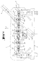
- the cutting machine (1) shown in FIG. 1 is, according to the example of embodiment shown, a mower (1) of the drag type intended to be coupled to a motor vehicle (not shown) which, during use, pulls in the direction in advance (2).
- This mower (1) has in outline a mobile frame (3), a drawbar (4), a cutting mechanism (5) and transmission members (6).
- the mobile frame (3) is on the one hand linked to the cutting mechanism (5), and on the other hand part at the drawbar (4).
- the drawbar (4) makes it possible to link the mower (1) to the motor vehicle thanks to a coupling structure (not shown).
- the cutting mechanism (5) driven by means of the transmission members (6), has a plurality of cutters (8) arranged next to the others along a line (9) transverse to the direction of advance (2).
- Each organ of section (8) is rotated in a respective direction (10, 10 ') around an axis of revolution (11) substantially vertical.
- each cutting member (8) is equipped with two cutting elements (13, 13 ') for cutting a standing product when said cutting member (8) is rotated.
- each cutting member (8) is composed, according to this first exemplary embodiment shown, a main structure (15) and two supports (16, 16 ').
- This cutting member (8) is also according to this exemplary embodiment shown, at least substantially symmetrical with respect to a plane of longitudinal symmetry (17) and with respect to a plane of symmetry transverse (18).
- the main structure (15) is composed, always according to the embodiment shown, of a sheet having a certain thickness and a number of bulges, concave parts and flat parts on the one hand to stiffen said main structure (15) and on the other hand to give it some form intended to transport the cut product in the opposite direction to the sense of advance (2).
- the main structure (15) comprises a first part (20) and a second part (21).
- This first part (20) is intended for to be fixed to a shaft (22) corresponding to a longitudinal axis (22a) at least substantially coincident with the axis of revolution (11).
- Said shaft (22) is part of the cutting mechanism (S) and it rotates the cutting member (8) corresponding.
- the first part (20) comprises, according to the example of shown embodiment. a central hole (23) and four peripheral holes (24).
- the central hole (23) of circular shape is located at least substantially in the center of the main structure (15).
- This central hole (23) has a longitudinal axis (23a) at less substantially coincident with the intersection of the planes of symmetry (17, 18).
- This central hole (23) is additionally intended to receive a corresponding shaft (22) previously described, and makes it possible to center the main structure (15) on said shaft (22) to ensure proper operation.
- the four holes peripherals (24) make it possible for them to fix the main structure (15), for the cutting member (8) to the corresponding shaft (11) by means of four screw (25).
- each screw (25) passes through the first part (20) of said main structure (15), and is screwed into said shaft (11).
- first part (20) of the main structure (15) is in the form of a truncated cone and extends upwards.
- This first part (20) is in addition at least substantially concentric to the central hole (23) as visible in Figure 3.
- the second part (21) is in turn elongated, more precisely the second portion (21) is substantially oval or elliptical in shape according to the longitudinal plane of symmetry (17) and the plane of transverse symmetry (18).
- This second portion (21) has a first end (27) located on either side of the longitudinal plane of symmetry (17), at which provided a first cutout (28) which is housed a first support (16).
- the second part (21) is symmetrical by relative to the plane of transverse symmetry (18).
- the second part (21) also has a second end (27 ') located on both sides of the plane of longitudinal symmetry (17), at which a second cutout (28 ') where is housed a second support (16').
- the cutting element (8) is symmetrical with respect to the plane of transverse symmetry (18), the second cut (28 ') and the second support (16') at least substantially the same as said first blank (28) and first support (16). That is why. only the first cut (28) and the first support (16) will be described in more detail.
- the first blank (28) has a first side (29) substantially orthogonal to the longitudinal plane of symmetry (17), a second side (30) and a third side (31).
- the second side (30) is contiguous to first side (29) through a first rounded shape (32), and extends substantially parallel to the longitudinal plane of symmetry (17).
- the third side (31) is in turn facing the second side (30) with respect to the plane of longitudinal symmetry (17), and is contiguous with the first side (29) via a second rounded shape (33).
- This third side (31) also extends substantially parallel to the longitudinal plane of symmetry (17).
- the three sides (29, 30, 31) of this first cutout (28) form a "U" whose base is constituted by the first side (29) and whose opening is directed towards the first end (27) of the second portion (21) of said main structure (15).
- the second part (21) of the main structure (15) of the cutting member (8) has an upper surface (35) and a lower surface (36). To the light of FIG. 5, it can be seen that the first end (27) of the second part (21) of the main structure (15) extends upwards around the second side (30) and the third side (31) of the first blank (28).
- the first support (16) has an upper portion (38) and a lower portion (39). According to one viewed from above, the upper part (38) is smaller than the lower part (39), and they are separated by a ridge (40).
- the lower part (39) of the support (16) extends beyond the limits of the upper portion (38) of said support (16), these boundaries being defined by the edge (40) described above. Therefore, when the first support (16) is housed in the first cutout (28). the bottom part (39) of the first support (16) bears against the lower surface (36) of the second portion (21) of the main structure (15), and the ridge (40) is at least substantially bearing against the first cut (28). So, the upper part (38) of the support (16) delimited by the ridge (40) also has a "U" shape which at least substantially marries the first cut (28).
- FIGS. 3 and 4 show again that when the support (16) is housed in the first cut (28), the lower portion (39) of said support (16) follows partly the shape of the second part (21) of the main structure (15) of the cutting member (8). Indeed, the end (41) of the lower part (39) has three sides (42, 43, 44) which are at least substantially parallel to three corresponding sides (46, 47, 48) of the second part (21) of the structure principal (15).
- Such a design of the cutting member (8) advantageously makes it possible to rigidify the latter.
- the lower part (39) of the support (16) comprises a reinforcing tab (50) at least substantially symmetrical with respect to the longitudinal plane of symmetry (17) and directed towards the first part (20) of the main structure (15) of the cutting member (8) when said support (16) is housed in the cutout (28).
- This reinforcing tab (50) bears on the lower surface (36) of the second portion (21) of the main structure (15).
- the support (16) is intended to be fixed to the second part (21) by means of corresponding welding seam (51, 52, 53).
- the cutting member (8) comprises, according to this first illustrated embodiment, two active zones (55, 55 ') each located at around a corresponding cutting element (13, 13 ') and exposed, during the work, the product previously cut by said cutting elements (13, 13 ').
- Each active zone (55, 55 ') contributes, when the cutting member (8) is rotated about the longitudinal axis (22a), transporting the cut product in the opposite direction in the direction of advance (2).
- each upper part (38, 38 ') of the support (16, 16') corresponding forms at least the corresponding active area (55, 55 ').
- each support (16, 16 ') largely forms the corresponding end (27, 27') of the second part (21) of the main structure (15) of the cutting member (8).
- the side (42, 42 ') of the end (41, 41') of the corresponding support (16. 16 ') is larger than the side (46, 46') of the structure principal (15).
- Each upper part (38, 38 ') of the corresponding support (16, 16') has a convex upper surface (56, 56 ') which allows advantageously to contribute to the transport of the cut product.
- the upper surface (35) of the second part (21) of the main structure (15) extends at its end (27, 27 ') corresponding substantially in the extension of the upper surface (56, 56 ') of the corresponding support (16, 16').
- Such continuity of surfaces (35; 56, 56 ') of the main structure (15) and supports (16, 16') allows advantageously to use the supports (16, 16 ') less and consequently to increase the life of the cutting member (8).
- each support (16, 16 ') forms at least the corresponding active area (55, 55 ') and therefore each support (16, 16') therefore forms a wear element. Therefore. each support (16, 16 ') comprises advantageously a thickness greater than the thickness of the second part (21) the main structure (15), which makes it possible to increase even further the life of said supports (16, 16 ') and therefore the life of the cutting member (8).
- each support (16, 16 ') has a hole (57, 57 '), of longitudinal axis (57a, 57'a) at least substantially parallel to the axis longitudinal (23a) of the central hole (23).
- Each hole (57, 57 ') is intended to receive a screw (58) supporting the element corresponding cutting section (13, 13 ').
- the screw (58) extends in the hole (57) upwards, and that it comprises a cylindrical part of guide (59) on which the cutting element (13) is guided.
- the screw (58) comprises also a shoulder (60) extending into a lower cavity (61) part of said hole (57), and resting on a lower bearing surface (62) situated at the bottom of said lower cavity (61).
- This hole (57) further comprises a profiled portion (63) at which extends another complementary profiled portion (64) belonging to the screw (58).
- These two profiled parts (63, 64) condemn a possible rotation of said screw (58) relative to the support (16).
- a nut (66) which extends entirely into an upper cavity (67) provided in the support (16) and forming part of the hole (57).
- This nut (66) is supported on a upper bearing surface (68) provided at the bottom of the upper cavity (67).
- the profiled portion (63) of the hole (57) and the lower cavity (61) are at least substantially centered on the longitudinal axis (57a) of said hole (57).
- the upper cavity (67) advantageously protects the nut (66) of the cut product, which prevents the latter from being damaged and can no longer to be undone to change the cutting element (13) when it is worn.
- FIG. 6 represents a cutting member (8A) according to a second form of realization.
- This body contains a number of elements that have been previously described. These elements will therefore keep the same number of landmark and will not be rewritten.
- This body also includes a number of number of elements whose mark is followed by the letter "A". These elements are comparable to elements of the cutting member (8) and they will only be described if this is necessary.
- the second embodiment of the cutter (8A) shown FIG. 6 is generally very similar to the cutter (8) described in FIG. previously. It should be noted that the main difference of this body of section (8A) relative to the cutting element (8) described above, lies in the fact that each support (16A, 16'A) (only the support (16A) being represented) is attached to the second part (21A) of the main structure (15A) of the cut (8A) removably. For this purpose, we see in the light of Figure 6 that the support (16A) is fixed to the second part (21A) by means of several screws (69) taking on one hand a bearing on the upper surface (35A) of said second part (21 A), and being screwed on the other hand onto said support (16A).
- the lower portion (39A) of the support (16A) is somewhat larger than the portion lower portion (39) of the support (16), and extends further beneath the lower surface (36A) of the second part (21A) on which it supports.
- the part lower section (39A) has tapped holes (70) into which the corresponding screws (69).
- the second part (21A) has meanwhile holes (72) through which the corresponding screws (69) extend.
- the screws (69) are, according to this second embodiment represent. screws (69) having a conical head and each hole (72) having a portion corresponding conic. This advantageously allows the screws (69) not to exceed the upper surface (35A) of the second part (21A) of the main structure (15A) of the cutting member (8A), during the establishment.
- screws (69) are at least substantially flush with the surface (35A) makes it possible to avoid premature wear of said screws (69), which allows easy disassembly thereof to replace said carrier (16A) when is used.
- each support (16, 16 ', 16A, 16'A) to the second portion (21, 21A) of the main structure (15, 15A) of the cutting member (8, 8A) using other means than those previously described.
Landscapes
- Life Sciences & Earth Sciences (AREA)
- Environmental Sciences (AREA)
- Harvester Elements (AREA)
- Turning (AREA)
- Crushing And Pulverization Processes (AREA)
- Finish Polishing, Edge Sharpening, And Grinding By Specific Grinding Devices (AREA)
- Laser Beam Processing (AREA)
- Sawing (AREA)
Claims (16)
- Schneidglied einer Schneidmaschine, das dazu bestimmt ist, in Drehung um eine Drehachse (11), die nach oben gerichtet ist, angetrieben zu werden, dasumfasst, dadurch gekennzeichnet, dass jeder Träger (16, 16'; 16A, 16'A) einen oberen Teil (38, 38') umfasst, der zumindest die entsprechende aktive Zone (55, 55') bildet.eine Hauptstruktur (15; 15A),mindestens zwei Träger (16, 16'; 16A, 16'A), die auf die Hauptstruktur (15; 15A) aufgesetzt sind, wobei jeder Träger (16, 16'; 16A, 16'A) dazu bestimmt ist, ein Schneidelement (13, 13') zu tragen, undmindestens zwei aktive Zonen (55, 55'), die sich jeweils in der Nähe eines entsprechenden Schneidelements (13, 13') befinden und jeweils während des Betriebs dem vorher von den Schneidelementen (13, 13') geschnittenen Produkt ausgesetzt sind, wobei jede aktive Zone (55, 55') zur Beförderung des Schnittguts beiträgt,
- Schneidglied einer Schneidmaschine nach Anspruch 1, dadurch gekennzeichnet, dass jeder obere Teil (38, 38') eines Trägers (16, 16'; 16A, 16'A) eine obere konvexe Fläche (56, 56') umfasst.
- Schneidglied einer Schneidmaschine nach Anspruch 1 oder 2, dadurch gekennzeichnet, dass die Hauptstruktur (15) einen ersten Teil (20), mittels welchem das Schneidglied (8; 8A) an einer Welle (22) mit einer Längsachse (22A) befestigt ist, die mit der Drehachse (11) zusammenfällt, und einen zweiten Teil (21; 21 A) mit länglicher Form umfasst, der einerseits aus einem ersten Ende (27; 27A), auf dessen Höhe sich ein erster Träger (16) befindet, und andererseits aus einem zweiten Ende (27'; 27'A), auf dessen Höhe sich ein zweiter Träger (16') befindet, besteht.
- Schneidglied einer Schneidmaschine nach Anspruch 3, dadurch gekennzeichnet, dass ihr zweiter Teil (21; 21A) im Wesentlichen ovale oder elliptische Form hat.
- Schneidglied einer Schneidmaschine nach Anspruch 3 oder 4, dadurch gekennzeichnet, dass ihr zweiter Teil (21; 21A) einerseits einen ersten Ausschnitt (28), der sich am ersten Ende (27; 27A) befindet, und andererseits einen zweiten Ausschnitt (28') umfasst, der sich am zweiten Ende (27', 27'A) befindet, wobei jeder Träger (16, 16'; 16A, 16'A) in dem entsprechenden Ausschnitt (28, 28') untergebracht ist.
- Schneidglied einer Schneidmaschine nach irgend einem der Ansprüche 3 bis 5, dadurch gekennzeichnet, dass jeder Träger (16, 16'; 16A, 16'A) zum Großteil das entsprechende Ende (27, 27'; 27A, 27'A) des zweiten Teils (21; 21 A) bildet.
- Schneidglied einer Schneidmaschine nach irgend einem der Ansprüche 3 bis 6, dadurch gekennzeichnet, dass der zweite Teil (21; 21A) an jedem Ende (27, 27'; 27A, 27'A) eine obere Fläche (35, 35'; 35A, 35'A) umfasst, die sich im Wesentlichen in der Verlängerung der oberen Fläche (56, 56') erstreckt, die der obere Teil (38, 38') des entsprechenden Trägers (16, 16'; 16A, 16'A) umfasst.
- Schneidglied einer Schneidmaschine nach irgend einem der Ansprüche 3 bis 7, dadurch gekennzeichnet, dass jeder Träger (16, 16'; 16A, 16'A) dicker als der zweite Teil (21; 21A) ist.
- Schneidglied einer Schneidmaschine nach irgend einem der Ansprüche 3 bis 8, dadurch gekennzeichnet, dass jeder Träger (16, 16'; 16A, 16'A) einen entsprechenden unteren Teil (39, 39'; 39A, 39'A) umfasst, der sich unter dem zweiten Teil (21, 21A) erstreckt.
- Schneidglied einer Schneidmaschine nach Anspruch 9, dadurch gekennzeichnet, dass der untere Teil (39, 39'; 39A, 39'A) jedes Trägers (16, 16'; 16A, 16'A) eine Verstärkungsklemme (50, 50') umfasst, die sich zum ersten Teil (20) hin erstreckt.
- Schneidglied einer Schneidmaschine nach Anspruch 9 oder 10, dadurch gekennzeichnet, dass sich der untere Teil (39, 39'; 39A, 39'A) jedes Trägers (16, 16'; 16A, 16'A) über die Grenzen des oberen Teils (38, 38') des Trägers (16, 16'; 16A, 16'A) hinaus erstreckt.
- Schneidglied einer Schneidmaschine nach irgend einem der Ansprüche 9 bis 11, dadurch gekennzeichnet, dass der untere Teil (39, 39'; 39A, 39'A) jedes Trägers (16, 16'; 16A, 16'A) teilweise der Form des zweiten Teils (21, 21A) folgt.
- Schneidglied einer Schneidmaschine nach irgend einem der Ansprüche 3 bis 12, dadurch gekennzeichnet, dass jeder Träger (16, 16') einen aufgesetzten Träger bildet, der am zweiten Teil (21) durch Schweißen befestigt ist.
- Schneidglied einer Schneidmaschine nach irgend einem der Ansprüche 3 bis 12, dadurch gekennzeichnet, dass jeder Träger (16A, 16'A) einen aufgesetzten Träger bildet, der am zweiten Teil (2 1 A) abnehmbar befestigt ist.
- Schneidglied einer Schneidmaschine nach irgend einem der Ansprüche 1 bis 14, dadurch gekennzeichnet, dass jeder Träger (16, 16'; 16A, 16'A) ein Loch (57, 57') umfasst, das es ermöglicht, darin das entsprechende Schneidelement (13, 13') anzubinden.
- Schneidmaschine, die dazu bestimmt ist, mit einem Motorfahrzeug verbunden zu werden, die einen Schneidmechanismus (5), der mit mindestens einem Schneidglied (8; 8A) versehen ist, das dazu bestimmt ist, in Drehung um eine nach oben gerichtete Drehachse (11) angetrieben zu werden, dadurch gekennzeichnet, dass das Schneidglied (8; 8A) ein Schneidglied nach irgend einem der Ansprüche 1 bis 15 ist.
Applications Claiming Priority (2)
| Application Number | Priority Date | Filing Date | Title |
|---|---|---|---|
| FR9901899 | 1999-02-15 | ||
| FR9901899A FR2774853B1 (fr) | 1999-02-15 | 1999-02-15 | Organe de coupe pour une machine de coupe notamment une faucheuse |
Publications (2)
| Publication Number | Publication Date |
|---|---|
| EP1029435A1 EP1029435A1 (de) | 2000-08-23 |
| EP1029435B1 true EP1029435B1 (de) | 2004-01-07 |
Family
ID=9542115
Family Applications (1)
| Application Number | Title | Priority Date | Filing Date |
|---|---|---|---|
| EP00440036A Expired - Lifetime EP1029435B1 (de) | 1999-02-15 | 2000-02-08 | Schneidewerkzeug einer Schneidemaschine |
Country Status (11)
| Country | Link |
|---|---|
| US (1) | US6305153B1 (de) |
| EP (1) | EP1029435B1 (de) |
| AT (1) | ATE257318T1 (de) |
| AU (1) | AU761954B2 (de) |
| CA (1) | CA2297999C (de) |
| DE (1) | DE60007569T2 (de) |
| DK (1) | DK1029435T3 (de) |
| ES (1) | ES2211488T3 (de) |
| FR (1) | FR2774853B1 (de) |
| NZ (1) | NZ502831A (de) |
| ZA (1) | ZA200000604B (de) |
Families Citing this family (9)
| Publication number | Priority date | Publication date | Assignee | Title |
|---|---|---|---|---|
| FR2802766B1 (fr) | 1999-12-23 | 2002-09-27 | Kuhn Sa | Element de coupe d'une machine de coupe de vegetaux rotative et machine de coupe de vegetaux rotative comportant un tel element de coupe |
| US7490459B2 (en) * | 2003-03-12 | 2009-02-17 | Vermeer Manufacturing Company | Mowing device, a knife adapter for such a mowing device and a retainer for such a mowing device |
| US20050193706A1 (en) * | 2003-03-12 | 2005-09-08 | Kent Thompson | Mowing device, a knife adapter for such a mowing device and a retainer for such a mowing device |
| US6834486B2 (en) * | 2003-03-12 | 2004-12-28 | Vermeer Manufacturing Company | Pivotal knife mounting arrangement |
| US20060168933A1 (en) * | 2005-02-01 | 2006-08-03 | Hill Robert G Jr | Blade for rotary cutting machine |
| USD647538S1 (en) * | 2010-05-17 | 2011-10-25 | Kuhn S.A. | Disc of rotary mower |
| USD640289S1 (en) * | 2010-05-17 | 2011-06-21 | Kuhn S.A. | Disc of rotary mower |
| USD645479S1 (en) | 2011-02-03 | 2011-09-20 | Cnh America Llc | Mower disc |
| US10306832B2 (en) * | 2017-07-26 | 2019-06-04 | Blount, Inc. | Blade pin and associated cutting element |
Family Cites Families (58)
| Publication number | Priority date | Publication date | Assignee | Title |
|---|---|---|---|---|
| NL6506452A (de) * | 1965-05-20 | 1966-11-21 | ||
| GB1326900A (en) * | 1969-12-05 | 1973-08-15 | Massey Ferguson Perkins Ltd | Mowing machines |
| FR2458981A1 (fr) | 1979-06-19 | 1981-01-09 | Kuhn Sa | Bati de machine agricole |
| FR2496391A1 (fr) | 1980-12-19 | 1982-06-25 | Kuhn Sa | Perfectionnement aux faucheuses |
| FR2502888A1 (fr) | 1981-04-02 | 1982-10-08 | Kuhn Sa | Barre de coupe a protecteur de disque lateral amovible |
| NL8105634A (nl) * | 1981-12-15 | 1983-07-01 | Zweegers P | Inrichting voor het maaien van gewas. |
| US4466234A (en) * | 1982-11-22 | 1984-08-21 | Sasaki Nouki Kabushiki Kaisha | Disk mower |
| US4531349A (en) * | 1984-03-23 | 1985-07-30 | Sperry Corporation | Rotary cutter for disc mower-conditioner |
| US4567716A (en) * | 1984-03-23 | 1986-02-04 | Sperry Corporation | Full quadrant crop lifter for disc mower-conditioners |
| US4549390A (en) * | 1984-03-23 | 1985-10-29 | Sperry Corporation | Crop lifter for disc mower-conditioners |
| FR2562758B1 (fr) | 1984-04-12 | 1988-05-20 | Kuhn Sa | Faucheuse |
| FR2565455B1 (fr) | 1984-06-07 | 1986-10-03 | Kuhn Sa | Perfectionnement aux dispositifs de conditionnement de fourrage |
| FR2566992B1 (fr) | 1984-07-06 | 1988-10-14 | Kuhn Sa | Faucheuse rotative. |
| FR2567710B1 (fr) | 1984-07-19 | 1987-05-07 | Kuhn Sa | Procede de transformation d'une machine de recolte pour l'amener d'une position de travail dans une position de transport, et machine de recolte utilisant ce procede |
| FR2571586B1 (fr) | 1984-10-16 | 1994-12-09 | Kuhn Sa | Faucheuse, verin amortisseur et dispositif amortisseur equipant cette faucheuse |
| FR2572881B1 (fr) | 1984-11-12 | 1989-04-21 | Kuhn Sa | Faucheuse comportant un chassis muni d'une structure intermediaire et de moyens destines a empecher l'accrochage de fourrage a la dite structure intermediaire. |
| FR2594627B1 (fr) | 1986-02-27 | 1988-06-17 | Kuhn Sa | Faucheuse rotative |
| FR2579405B1 (fr) | 1985-03-28 | 1987-06-19 | Kuhn Sa | Machine agricole a dispositif de transmission perfectionne |
| FR2584889B1 (fr) | 1985-07-18 | 1989-05-05 | Kuhn Sa | Faucheuse avec mecanisme de delestage |
| DE3774455D1 (de) * | 1986-02-24 | 1991-12-19 | Lely Nv C Van Der | Maehmaschine. |
| FR2597293B1 (fr) | 1986-04-17 | 1988-08-05 | Kuhn Sa | Faucheuse rotative avec barre de coupe et structure support. |
| NL8601110A (nl) * | 1986-04-29 | 1987-11-16 | Multinorm Bv | Maaiinrichting met verbeterde mesbevestiging. |
| FR2598058B1 (fr) | 1986-05-02 | 1989-10-13 | Kuhn Sa | Faucheuse munie d'au moins un organe de coupe surmonte par un tambour rotatif |
| FR2608362B1 (fr) | 1986-12-22 | 1990-10-12 | Kuhn Sa | Faucheuse avec dispositif de suspension des groupes de fauche perfectionne |
| FR2624688B1 (fr) | 1987-12-21 | 1990-05-18 | Kuhn Sa | Faucheuse avec rigidification perfectionnee de la barre de coupe |
| FR2626137B1 (fr) | 1988-01-22 | 1991-09-06 | Kuhn Sa | Faucheuse rotative comportant des organes de coupe s'etendant au-dessus d'un carter par l'intermediaire de paliers de guidage et d'entrainement |
| FR2627942B1 (fr) | 1988-03-04 | 1990-08-10 | Kuhn Sa | Perfectionnement aux machines agricoles pour la recolte |
| FR2628596B1 (fr) | 1988-03-15 | 1991-09-06 | Kuhn Sa | Faucheuse a entrainement direct |
| FR2638056B1 (fr) | 1988-10-26 | 1991-06-07 | Kuhn Sa | Faucheuse avec montage perfectionne des organes de coupe |
| FR2642610B1 (fr) | 1989-02-07 | 1991-05-17 | Kuhn Sa | Faucheuse avec dispositif de securite a declenchement |
| FR2654893B1 (fr) | 1989-11-24 | 1992-02-21 | Kuhn Sa | Machine agricole avec dispositif de suspension du groupe d'organes de travail perfectionne. |
| FR2654896B1 (fr) | 1989-11-24 | 1992-02-21 | Kuhn Sa | Faucheuse comportant un groupe d'organes de travail s'etendant au travail transversalement a la direction d'avance. |
| FR2654897B1 (fr) | 1989-11-24 | 1992-03-20 | Kuhn Sa | Faucheuse avec dispositif d'allegement perfectionne. |
| FR2660518B1 (fr) | 1990-04-05 | 1993-06-11 | Kuhn Sa | Machine agricole avec dispositif de detection de la position intermediaire du moyen de liaison. |
| FR2668881B1 (fr) | 1990-11-12 | 1994-05-27 | Kuhn Sa | Machine agricole, en particulier faucheuse, s'adaptant aisement au relief du terrain et comportant un carter pivotant. |
| FR2668880B1 (fr) | 1990-11-12 | 1995-06-30 | Kuhn Sa | Procede de transformation d'une machine de recolte pour l'amener d'une position de transport dans une position de travail, et machine de recolte. |
| US5272859A (en) * | 1992-04-14 | 1993-12-28 | Hay & Forage Industries | Mechanical drive center pivot mower conditioner |
| FR2691041B1 (fr) | 1992-05-14 | 1999-02-26 | Kuhn Sa | Machine de coupe, notamment faucheuse, s'adaptant aisement au relief du sol. |
| FR2691037B1 (fr) | 1992-05-14 | 1999-02-26 | Kuhn Sa | Machine agricole, notamment faucheuse, avec un dispositif de delestage et de levage perfectionne. |
| FR2696898B1 (fr) | 1992-10-16 | 1994-12-09 | Kuhn Sa | Faucheuse avec un entraînement perfectionné des rouleaux de traitement. |
| FR2712764B1 (fr) | 1993-11-23 | 1996-02-09 | Kuhn Sa | Machine agricole à timon perfectionné. |
| FR2715797B1 (fr) | 1994-02-08 | 1996-04-12 | Kuhn Sa | Faucheuse rotative avec barre de coupe et structure support. |
| FR2719189B1 (fr) | 1994-04-29 | 1996-07-05 | Kuhn Sa | Faucheuse à dispositif de sécurité. |
| FR2724689B1 (fr) | 1994-09-16 | 1997-01-24 | Kuhn Sa | Mecanisme de verrouillage destine a equiper principalement une machine agricole |
| FR2726152B1 (fr) | 1994-10-28 | 1997-01-24 | Kuhn Sa | Machine agricole destinee a la coupe de vegetaux avec dispositif de protection perfectionne |
| FR2726343B1 (fr) | 1994-10-28 | 1997-01-24 | Kuhn Sa | Valve a quatre orifices de raccordement et deux positions |
| FR2733873B1 (fr) | 1995-05-10 | 1997-08-01 | Kuhn Sa | Faucheuse avec un dispositif d'allegement du mecanisme de recolte reglable a distance |
| US5784866A (en) * | 1996-06-25 | 1998-07-28 | New Holland North America, Inc. | Disc cutterbar for agricultural implements |
| US5715663A (en) * | 1995-06-26 | 1998-02-10 | New Holland North America, Inc. | Crop mover for rotary disc cutter |
| FR2736505B1 (fr) | 1995-07-13 | 1997-09-26 | Kuhn Sa | Faucheuse avec un dispositif d'andainage perfectionne |
| FR2743978B1 (fr) | 1996-01-31 | 1998-04-17 | Kuhn Sa | Faucheuse avec organe de depose perfectionne |
| US6003291A (en) | 1996-04-09 | 1999-12-21 | Kuhn, S.A. | Agriculture machine |
| FR2747006B1 (fr) | 1996-04-09 | 1998-05-29 | Kuhn Sa | Machine agricole avec moyen de liaison a un vehicule tracteur et carter de renvoi pivotants |
| FR2749127B1 (fr) | 1996-05-28 | 1998-08-07 | Kuhn Sa | Machine de coupe de vegetaux, destinee a etre attelee a un vehicule moteur, avec un dispositif de verrouillage du mecanisme de coupe |
| FR2751166B1 (fr) | 1996-07-22 | 1998-09-18 | Kuhn Sa | Machine agricole de recolte de vegetaux avec deux unites de conditionnement |
| FR2756135B1 (fr) * | 1996-11-26 | 1999-01-29 | Agram | Disque de faucheuse et de faucheuse-conditionneuse |
| US5845468A (en) * | 1997-06-26 | 1998-12-08 | Deere & Company | Rotary mower cutter disc having replaceable knife mount shield |
| FR2767633B1 (fr) | 1997-09-02 | 1999-10-08 | Kuhn Sa | Dispositif de conditionnement ameliore, machine pour le conditionnement et faucheuse conditionneuse comportant un tel dispositif |
-
1999
- 1999-02-15 FR FR9901899A patent/FR2774853B1/fr not_active Expired - Fee Related
-
2000
- 2000-02-04 CA CA002297999A patent/CA2297999C/fr not_active Expired - Fee Related
- 2000-02-04 US US09/498,373 patent/US6305153B1/en not_active Expired - Lifetime
- 2000-02-08 AT AT00440036T patent/ATE257318T1/de active
- 2000-02-08 EP EP00440036A patent/EP1029435B1/de not_active Expired - Lifetime
- 2000-02-08 DE DE60007569T patent/DE60007569T2/de not_active Expired - Lifetime
- 2000-02-08 DK DK00440036T patent/DK1029435T3/da active
- 2000-02-08 ES ES00440036T patent/ES2211488T3/es not_active Expired - Lifetime
- 2000-02-09 AU AU14999/00A patent/AU761954B2/en not_active Ceased
- 2000-02-09 ZA ZA200000604A patent/ZA200000604B/xx unknown
- 2000-02-14 NZ NZ502831A patent/NZ502831A/en not_active IP Right Cessation
Also Published As
| Publication number | Publication date |
|---|---|
| ZA200000604B (en) | 2000-09-07 |
| AU1499900A (en) | 2000-08-17 |
| EP1029435A1 (de) | 2000-08-23 |
| DE60007569T2 (de) | 2004-12-16 |
| DE60007569D1 (de) | 2004-02-12 |
| FR2774853B1 (fr) | 2001-02-16 |
| CA2297999C (fr) | 2008-04-29 |
| DK1029435T3 (da) | 2004-05-17 |
| ES2211488T3 (es) | 2004-07-16 |
| NZ502831A (en) | 2001-06-29 |
| CA2297999A1 (fr) | 2000-08-15 |
| US6305153B1 (en) | 2001-10-23 |
| FR2774853A1 (fr) | 1999-08-20 |
| AU761954B2 (en) | 2003-06-12 |
| ATE257318T1 (de) | 2004-01-15 |
Similar Documents
| Publication | Publication Date | Title |
|---|---|---|
| EP0408090B1 (de) | Kreiselmäher | |
| FR2470653A1 (fr) | Alesoir a plaquette de coupe reversible de forme rectangulaire | |
| EP1029435B1 (de) | Schneidewerkzeug einer Schneidemaschine | |
| EP1110442B1 (de) | Schneideelement für Mäher | |
| FR2918909A1 (fr) | Outil d'usinage rotatif du type a plaquettes amovibles avec insert en diamant polycristallin. | |
| FR1464371A (fr) | Rotor pour appareils destinés à la désagrégation de la paille ou matière similaire | |
| EP1900269B1 (de) | Verschleissstück und seine Befestigung, Pflugkörper und Pflug, die ein solches Verschleissstück umfassen | |
| FR2857557A1 (fr) | Dispositif de couplage rapide avec elements de crochets doubles | |
| FR2744048A1 (fr) | Outil de coupe pour realiser des trous | |
| FR2870431A1 (fr) | Appareil a disque rotatif a dents de deux types pour broyer des souches | |
| EP1038428B1 (de) | Schneidevorrichtung einer Mähmaschine | |
| FR2703610A1 (fr) | Plaquette de coupe et outil équipé de telles plaquettes . | |
| FR2551684A1 (fr) | Ensemble de poste d'outils pour machines-outils | |
| FR3055083A1 (fr) | Dispositif de montage/demontage d'au moins un marteau sur un rotor de machine agricole, et outil equipe d'un tel dispositif | |
| FR2630289A1 (fr) | Groupe faucheur dont les outils de coupe sont lies a leur organe de coupe par un dispositif de liaison a axe et ressort a lame et machine de fauchage utilisant un tel groupe faucheur | |
| FR2506642A1 (fr) | Outil de tour a plaquette de coupe amovible orientable | |
| FR2525856A1 (fr) | Faucheuse | |
| EP0891687B1 (de) | Lösbares Gerät für Bodenbearbeitungsmaschine | |
| FR2554309A1 (fr) | Couteau pour tete de coupe de machine de recolte de fourrage | |
| FR2772551A1 (fr) | Dispositif elevateur de fourrage destine a equiper un element de coupe rotatif de faucheuse | |
| FR2746044A1 (fr) | Outil a plaquettes interchangeables affutables et procede d'affutage des plaquettes de coupe | |
| FR2736504A1 (fr) | Lame de coupe pour debroussailleur rotatif a axe vertical | |
| FR2477945A1 (fr) | Dispositif de coupe pour une coupeuse a bois produisant des copeaux | |
| FR1464375A (fr) | Dispositif pour le découpage de bandes de papier dans le sens de la longueur | |
| FR2742299A1 (fr) | Faucheuse a disques |
Legal Events
| Date | Code | Title | Description |
|---|---|---|---|
| PUAI | Public reference made under article 153(3) epc to a published international application that has entered the european phase |
Free format text: ORIGINAL CODE: 0009012 |
|
| AK | Designated contracting states |
Kind code of ref document: A1 Designated state(s): AT BE CH CY DE DK ES FI FR GB GR IE IT LI LU MC NL PT SE |
|
| AX | Request for extension of the european patent |
Free format text: AL;LT;LV;MK;RO;SI |
|
| 17P | Request for examination filed |
Effective date: 20010131 |
|
| AKX | Designation fees paid |
Free format text: AT BE CH CY DE DK ES FI FR GB GR IE IT LI LU MC NL PT SE |
|
| 17Q | First examination report despatched |
Effective date: 20021104 |
|
| GRAP | Despatch of communication of intention to grant a patent |
Free format text: ORIGINAL CODE: EPIDOSNIGR1 |
|
| GRAS | Grant fee paid |
Free format text: ORIGINAL CODE: EPIDOSNIGR3 |
|
| GRAA | (expected) grant |
Free format text: ORIGINAL CODE: 0009210 |
|
| AK | Designated contracting states |
Kind code of ref document: B1 Designated state(s): AT BE CH CY DE DK ES FI FR GB GR IE IT LI LU MC NL PT SE |
|
| PG25 | Lapsed in a contracting state [announced via postgrant information from national office to epo] |
Ref country code: CY Free format text: LAPSE BECAUSE OF FAILURE TO SUBMIT A TRANSLATION OF THE DESCRIPTION OR TO PAY THE FEE WITHIN THE PRESCRIBED TIME-LIMIT Effective date: 20040107 |
|
| REG | Reference to a national code |
Ref country code: GB Ref legal event code: FG4D Free format text: NOT ENGLISH |
|
| REG | Reference to a national code |
Ref country code: CH Ref legal event code: EP |
|
| PG25 | Lapsed in a contracting state [announced via postgrant information from national office to epo] |
Ref country code: LU Free format text: LAPSE BECAUSE OF NON-PAYMENT OF DUE FEES Effective date: 20040208 |
|
| REG | Reference to a national code |
Ref country code: IE Ref legal event code: FG4D Free format text: FRENCH |
|
| REF | Corresponds to: |
Ref document number: 60007569 Country of ref document: DE Date of ref document: 20040212 Kind code of ref document: P |
|
| PG25 | Lapsed in a contracting state [announced via postgrant information from national office to epo] |
Ref country code: MC Free format text: LAPSE BECAUSE OF NON-PAYMENT OF DUE FEES Effective date: 20040228 |
|
| PG25 | Lapsed in a contracting state [announced via postgrant information from national office to epo] |
Ref country code: CH Free format text: LAPSE BECAUSE OF NON-PAYMENT OF DUE FEES Effective date: 20040229 Ref country code: LI Free format text: LAPSE BECAUSE OF NON-PAYMENT OF DUE FEES Effective date: 20040229 |
|
| REG | Reference to a national code |
Ref country code: SE Ref legal event code: TRGR |
|
| GBT | Gb: translation of ep patent filed (gb section 77(6)(a)/1977) |
Effective date: 20040316 |
|
| PG25 | Lapsed in a contracting state [announced via postgrant information from national office to epo] |
Ref country code: GR Free format text: LAPSE BECAUSE OF FAILURE TO SUBMIT A TRANSLATION OF THE DESCRIPTION OR TO PAY THE FEE WITHIN THE PRESCRIBED TIME-LIMIT Effective date: 20040407 |
|
| REG | Reference to a national code |
Ref country code: DK Ref legal event code: T3 |
|
| REG | Reference to a national code |
Ref country code: ES Ref legal event code: FG2A Ref document number: 2211488 Country of ref document: ES Kind code of ref document: T3 |
|
| REG | Reference to a national code |
Ref country code: CH Ref legal event code: PL |
|
| PLBE | No opposition filed within time limit |
Free format text: ORIGINAL CODE: 0009261 |
|
| STAA | Information on the status of an ep patent application or granted ep patent |
Free format text: STATUS: NO OPPOSITION FILED WITHIN TIME LIMIT |
|
| 26N | No opposition filed |
Effective date: 20041008 |
|
| PG25 | Lapsed in a contracting state [announced via postgrant information from national office to epo] |
Ref country code: PT Free format text: LAPSE BECAUSE OF NON-PAYMENT OF DUE FEES Effective date: 20040607 |
|
| REG | Reference to a national code |
Ref country code: FR Ref legal event code: PLFP Year of fee payment: 17 |
|
| PGFP | Annual fee paid to national office [announced via postgrant information from national office to epo] |
Ref country code: ES Payment date: 20160205 Year of fee payment: 17 |
|
| PGFP | Annual fee paid to national office [announced via postgrant information from national office to epo] |
Ref country code: BE Payment date: 20160122 Year of fee payment: 17 Ref country code: GB Payment date: 20160127 Year of fee payment: 17 Ref country code: SE Payment date: 20160126 Year of fee payment: 17 |
|
| REG | Reference to a national code |
Ref country code: FR Ref legal event code: PLFP Year of fee payment: 18 |
|
| PG25 | Lapsed in a contracting state [announced via postgrant information from national office to epo] |
Ref country code: BE Free format text: LAPSE BECAUSE OF NON-PAYMENT OF DUE FEES Effective date: 20170228 |
|
| REG | Reference to a national code |
Ref country code: SE Ref legal event code: EUG |
|
| GBPC | Gb: european patent ceased through non-payment of renewal fee |
Effective date: 20170208 |
|
| PG25 | Lapsed in a contracting state [announced via postgrant information from national office to epo] |
Ref country code: SE Free format text: LAPSE BECAUSE OF NON-PAYMENT OF DUE FEES Effective date: 20170209 |
|
| REG | Reference to a national code |
Ref country code: BE Ref legal event code: MM Effective date: 20170228 |
|
| REG | Reference to a national code |
Ref country code: FR Ref legal event code: PLFP Year of fee payment: 19 |
|
| PG25 | Lapsed in a contracting state [announced via postgrant information from national office to epo] |
Ref country code: GB Free format text: LAPSE BECAUSE OF NON-PAYMENT OF DUE FEES Effective date: 20170208 |
|
| PGFP | Annual fee paid to national office [announced via postgrant information from national office to epo] |
Ref country code: NL Payment date: 20180226 Year of fee payment: 19 |
|
| PGFP | Annual fee paid to national office [announced via postgrant information from national office to epo] |
Ref country code: DK Payment date: 20180223 Year of fee payment: 19 Ref country code: DE Payment date: 20180227 Year of fee payment: 19 Ref country code: FI Payment date: 20180227 Year of fee payment: 19 |
|
| REG | Reference to a national code |
Ref country code: ES Ref legal event code: FD2A Effective date: 20180507 |
|
| PGFP | Annual fee paid to national office [announced via postgrant information from national office to epo] |
Ref country code: AT Payment date: 20180119 Year of fee payment: 19 Ref country code: FR Payment date: 20180227 Year of fee payment: 19 Ref country code: IE Payment date: 20180227 Year of fee payment: 19 Ref country code: IT Payment date: 20180222 Year of fee payment: 19 |
|
| PG25 | Lapsed in a contracting state [announced via postgrant information from national office to epo] |
Ref country code: ES Free format text: LAPSE BECAUSE OF NON-PAYMENT OF DUE FEES Effective date: 20170209 |
|
| REG | Reference to a national code |
Ref country code: DE Ref legal event code: R119 Ref document number: 60007569 Country of ref document: DE |
|
| REG | Reference to a national code |
Ref country code: DK Ref legal event code: EBP Effective date: 20190228 |
|
| REG | Reference to a national code |
Ref country code: NL Ref legal event code: MM Effective date: 20190301 |
|
| REG | Reference to a national code |
Ref country code: AT Ref legal event code: MM01 Ref document number: 257318 Country of ref document: AT Kind code of ref document: T Effective date: 20190208 |
|
| PG25 | Lapsed in a contracting state [announced via postgrant information from national office to epo] |
Ref country code: FI Free format text: LAPSE BECAUSE OF NON-PAYMENT OF DUE FEES Effective date: 20190208 |
|
| REG | Reference to a national code |
Ref country code: IE Ref legal event code: MM4A |
|
| PG25 | Lapsed in a contracting state [announced via postgrant information from national office to epo] |
Ref country code: AT Free format text: LAPSE BECAUSE OF NON-PAYMENT OF DUE FEES Effective date: 20190208 |
|
| PG25 | Lapsed in a contracting state [announced via postgrant information from national office to epo] |
Ref country code: IE Free format text: LAPSE BECAUSE OF NON-PAYMENT OF DUE FEES Effective date: 20190208 Ref country code: DE Free format text: LAPSE BECAUSE OF NON-PAYMENT OF DUE FEES Effective date: 20190903 Ref country code: DK Free format text: LAPSE BECAUSE OF NON-PAYMENT OF DUE FEES Effective date: 20190228 Ref country code: NL Free format text: LAPSE BECAUSE OF NON-PAYMENT OF DUE FEES Effective date: 20190301 |
|
| PG25 | Lapsed in a contracting state [announced via postgrant information from national office to epo] |
Ref country code: IT Free format text: LAPSE BECAUSE OF NON-PAYMENT OF DUE FEES Effective date: 20190208 Ref country code: FR Free format text: LAPSE BECAUSE OF NON-PAYMENT OF DUE FEES Effective date: 20190228 |