EP1029774A2 - In Fertigungslinien für Kraftfahrzeuge einsetzbare Spannvorrichtung und Fertigungslinie mit einer solchen Spannvorrichtung - Google Patents
In Fertigungslinien für Kraftfahrzeuge einsetzbare Spannvorrichtung und Fertigungslinie mit einer solchen Spannvorrichtung Download PDFInfo
- Publication number
- EP1029774A2 EP1029774A2 EP00102358A EP00102358A EP1029774A2 EP 1029774 A2 EP1029774 A2 EP 1029774A2 EP 00102358 A EP00102358 A EP 00102358A EP 00102358 A EP00102358 A EP 00102358A EP 1029774 A2 EP1029774 A2 EP 1029774A2
- Authority
- EP
- European Patent Office
- Prior art keywords
- production line
- clamping
- sidecar
- clamping device
- behind
- Prior art date
- Legal status (The legal status is an assumption and is not a legal conclusion. Google has not performed a legal analysis and makes no representation as to the accuracy of the status listed.)
- Granted
Links
- 238000004519 manufacturing process Methods 0.000 title claims description 58
- 238000003466 welding Methods 0.000 claims description 24
- 239000000969 carrier Substances 0.000 claims description 8
- 230000006978 adaptation Effects 0.000 description 1
- 238000000034 method Methods 0.000 description 1
- 239000011295 pitch Substances 0.000 description 1
Images

Classifications
-
- B—PERFORMING OPERATIONS; TRANSPORTING
- B62—LAND VEHICLES FOR TRAVELLING OTHERWISE THAN ON RAILS
- B62D—MOTOR VEHICLES; TRAILERS
- B62D65/00—Designing, manufacturing, e.g. assembling, facilitating disassembly, or structurally modifying motor vehicles or trailers, not otherwise provided for
- B62D65/02—Joining sub-units or components to, or positioning sub-units or components with respect to, body shell or other sub-units or components
- B62D65/18—Transportation, conveyor or haulage systems specially adapted for motor vehicle or trailer assembly lines
Definitions
- the invention relates to a in production lines for Motor vehicles can be used in the direction of the production line movable clamping device for a transport device movable in the direction of the production line Body shells, which on both sides of the production line Side parts and cross members reaching over the body shell with clamping bodies for clamping the body shell and in which the cross member in the working position by a lock to a component bridging the body shell are to be coupled together.
- the invention further relates to a production line with such a clamping device.
- a tensioning device of the above type is the subject DE 195 33 389 A1.
- This document also describes a production line with such a clamping device.
- the known clamping device is one as a whole movable base frame is provided, on which the side parts are arranged.
- the transport device for the body shell is movably arranged on the base frame.
- the clamping device has two in a row arranged base frame with side parts, which wear differently designed clamping bodies, so that in the Production line for welding two different body shells either one or the other clamping device can be used.
- the invention is based on the problem of a tensioning device of the type mentioned in the introduction so that the fastest possible adaptation to different body styles is possible.
- a production line is also planned created with such a jig be the quickest possible change between different Body styles allowed.
- the first-mentioned problem is solved by that on both sides of the transport device a common one, below the transport device guiding base frame routes for one at a time Side of the transport device can be moved separately Sidecars are arranged so that the sidecar is only the Carries side parts of one side of the transport device and that clamping means for connecting the sidecar with the base frame are provided.
- the routes can be designed differently. Man can rely on components that have proven themselves in production lines fall back when the routes through by a distance arranged, firmly connected to the base frame Roller carrier formed with rotatably mounted rollers are on which the respective sidecar with a Support frame is supported.
- the clamping means are intended to create a frictional connection between the Create the base frame and the sidecar. That leaves realize themselves in a particularly simple manner if according to another development of the invention Clamping means arranged on both sides of the roller carrier and for clamping the support frame within the roller carrier are trained.
- Clamping device can do this with little effort Open position are moved, in which the clamping body have a sufficient distance from the body shell, if according to another development of the invention, the side parts with the respective cross member by one in parallel to the production line horizontal axis from Production line can be pivoted outwards with the Support frame are connected.
- the sidecar all clamping bodies for the body shell including the lower clamps have.
- the second problem namely the creation of a Production line with the clamping device described above is solved according to the invention in that at each Side of the production line at least one parking space for an additional sidecar of a pair of sidecars is provided for a further body shell variant and if the production line means to replace the sidecar having.
- Such a production line allows Replacement of a complete clamping device by a process of the two sidecars without the transport device of the production line got to. Therefore, such a change is possible very quickly, so that on a production line in quick succession different types of body shells can be manufactured can.
- a production line according to the invention can Use of the side of the production line is available standing place a large number of different types can be processed by body shells without the welding robot hinder the exchange of the sidecar if before and behind a welding station on the production line several parking spaces next to each other for the production line a sidecar are provided and if Exchange of sidecars on each side of the production line a transport route behind welding robots Welding station from the parking spaces in front of the welding station leads to the parking spaces behind the welding station.
- Welding robots can be seen from every side of the production line drive right up to the body-in-white without here the path of the sidecar is in the way, if according to another development of the invention in each case a welding robot to one side of the production line Entering the sidecar track along the production line is formed between the roller carriers.
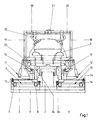
- FIG. 1 shows a base frame 1 on which one Transport device 2 of a production line shown in Figure 2 3 is arranged.
- This transport device 2 is used to transport body shells 4.
- On the base frame 1 are on both sides of the transport device 2 Roller carriers 5, 6 with rollers 7, 8 arranged fixed.
- Roller carriers 5, 6 with rollers 7, 8 arranged fixed.
- Several such roller carriers positioned one behind the other 5, 6 together form a parallel to the Transport device 2 running track 9, 10 for a sidecar 11, 12.
- Each sidecar 11, 12 has a supporting frame supported on the rollers 7, 8 13, 14.
- On the support frame 13, 14 are each around a horizontal axis 15, 16 pivotable side parts 17, 18 fastened with cross members 19, 20. In working position are the two cross members 19, 20 by a lock 21 firmly connected.
- the side parts 17, 18 and cross member 19, 20 carry clamping bodies 22, 23 for the body-in-white.
- Clamping bodies designed as lower clamps 24 also provided on the side car 11, 12.
- Clamping means 34 serve to support frames 13, 14 in the Roller carriers 5, 6 jam when the sidecar 11, 12 are in the working position. To support this the clamping means 34 when pressurized against one Side surface of the support frame and against the respective Roller carriers 5, 6 from.
- FIG. 2 one can see that in production line 3 Body shells 4, 4a, 4b, 4c and 4d.
- the Body shell 4b in a welding station 25 on each Side of production line 3 a total of three welding robots 26, 27, 28.
- FIG. 2 next to production line 3 on each side two sidecars 11, 12 and 11a, 12a, through which each a body shell 4a, 4b is tensioned.
- the sidecars 11, 12; 11a and 12a are parallel on the routes 9, 10 movable to production line 3.
- the welding robot 28 and the opposite, not positioned The welding robot has entered path 9 or 10, a position as close as possible to the body shell 4b to take.
Landscapes
- Engineering & Computer Science (AREA)
- Manufacturing & Machinery (AREA)
- Chemical & Material Sciences (AREA)
- Combustion & Propulsion (AREA)
- Transportation (AREA)
- Mechanical Engineering (AREA)
- Automobile Manufacture Line, Endless Track Vehicle, Trailer (AREA)
- Automatic Assembly (AREA)
- Jigs For Machine Tools (AREA)
- Chain Conveyers (AREA)
Abstract
Description
- Fig.1
- eine Vorderansicht einer Spannvorrichtung nach der Erfindung in Spannstellung,
- Fig.2
- eine Draufsicht auf einen für die Erfindung wesentlichen Teilbereich einer Fertigungslinie.
- 1
- Grundrahmen
- 2
- Transportvorrichtung
- 3
- Fertigungslinie
- 4
- Rohkarosse
- 5
- Rollenträger
- 6
- Rollenträger
- 7
- Laufrolle
- 8
- Laufrolle
- 9
- Fahrweg
- 10
- Fahrweg
- 11
- Seitenwagen
- 12
- Seitenwagen
- 13
- Tragrahmen
- 14
- Tragrahmen
- 15
- Achse
- 16
- Achse
- 17
- Seitenteil
- 18
- Seitenteil
- 19
- Querträger
- 20
- Querträger
- 21
- Verriegelung
- 22
- Spannkörper
- 23
- Spannkörper
- 24
- Unterspanner
- 25
- Schweißstation
- 26
- Schweißroboter
- 27
- Schweißroboter
- 28
- Schweißroboter
- 29
- Stellplatz
- 30
- Stellplatz
- 31
- Transportweg
- 32
- Seitenwagen
- 33
- Seitenwagen
- 34
- Klemmmittel
Claims (8)
- In Fertigungslinien für Kraftfahrzeuge einsetzbare, in Richtung der Fertigungslinie verfahrbare Spannvorrichtung für auf eine Transportvorrichtung in Richtung der Fertigungslinie verfahrbare Rohkarossen, welche zu beiden Seiten der Fertigungslinie Seitenteile und über die Rohkarosse greifende Querträger mit Spannkörpern zum Spannen der Rohkarosse aufweist und bei der die Querträger in Arbeitsstellung durch eine Verriegelung zu einem die Rohkarosse überbrückenden Bauteil miteinander zu kuppeln sind, dadurch gekennzeichnet, dass auf beiden Seiten der Transportvorrichtung (2) auf einem gemeinsamen, unterhalb der Transportvorrichtung (2) führenden Grundrahmen (1) Fahrwege (9, 10) für jeweils einen auf einer Seite der Transportvorrichtung (2) separat verfahrbaren Seitenwagen (11, 12) angeordnet sind, dass der Seitenwagen (11, 12) nur die Seitenteile (17, 18) einer Seite der Transportvorrichtung (2) trägt und dass Klemmmittel (34) zum Verbinden der Seitenwagen (11, 12) mit dem Grundrahmen (1) vorgesehen sind.
- Spannvorrichtung nach Anspruch 1, dadurch gekennzeichnet, dass die Fahrwege (9, 10) durch mit Abstand hintereinander angeordnete, fest mit dem Grundrahmen (1) verbundene Rollenträger (5, 6) mit drehbar gelagerten Laufrollen (7, 8) gebildet sind, auf denen der jeweilige Seitenwagen (11, 12) mit einem Tragrahmen (13, 14) abgestützt ist.
- Spannvorrichtung nach Anspruch 2, dadurch gekennzeichnet, dass die Klemmmittel an beiden Seiten des Rollenträgers angeordnet und zum Einspannen des Tragrahmens (13, 14) innerhalb des Rollenträgers (5, 6) ausgebildet sind.
- Spannvorrichtung nach zumindest einem der vorangehenden Ansprüche, dadurch gekennzeichnet, dass die Seitenteile (17, 18) mit dem jeweiligen Querträger (19, 20) jeweils um eine parallel zur Fertigungslinie horizontal verlaufende Achse (15, 16) von der Fertigungslinie weg nach außen schwenkbar mit dem Tragrahmen (13, 14) verbunden sind.
- Spannvorrichtung nach zumindest einem der vorangehenden Ansprüche, dadurch gekennzeichnet, dass die Seitenwagen (11, 12) sämtliche Spannkörper (22, 23) für die Rohkarosse (4) einschließlich der Unterspanner (24) aufweisen.
- Fertigungslinie mit einer Spannvorrichtung nach zumindest einem der vorangehenden Ansprüche, bei der hintereinander zwei komplette Spannvorrichtungen für zwei unterschiedliche Rohkarossen angeordnet sind, dadurch gekennzeichnet, dass an jeder Seite der Fertigungslinie (3) zumindest ein Stellplatz (29, 30; 29a, 30a; (29b, 30b; 29c, 30c)) für einen zusätzlichen Seitenwagen (32, 33) eines Seitenwagenpaares für eine weitere Rohkarossenvariante vorgesehen ist und dass die Fertigungslinie (3) Mittel zum Austausch der Seitenwagen (11, 12, 11a, 12a, 32, 33) aufweist.
- Fertigungslinie nach Anspruch 6, dadurch gekennzeichnet, dass vor und hinter einer Schweißstation (25) der Fertigungslinie (3) quer zur Fertigungslinie (3) nebeneinander mehrere Stellplätze (29, 30; 29a, 30a) für jeweils einen seitenwagen (11, 12) vorgesehen sind und dass zum Austausch von Seitenwagen (11, 12) auf jeder Seite der Fertigungslinie (3) ein Transportweg (31, 31a) hinter Schweißrobotern (26, 27, 28) der Schweißstation (25) von den Stellplätzen (29, 30; 29a, 30a) vor der Schweißstation (25) zu den Stellplätzen (29b, 30b; 29c, 30c) hinter der Schweißstation (25) führt.
- Fertigungslinie nach zumindest einem der vorangehenden Ansprüche, dadurch gekennzeichnet, dass jeweils ein Schweißroboter (28) einer Seite der Fertigungslinie (3) zum Einfahren in den Fahrweg (9, 10) der Seitenwagen (11, 12, 11a, 12a) entlang der Fertigungslinie (3) zwischen den Rollenträgern (5, 6) ausgebildet ist.
Applications Claiming Priority (2)
| Application Number | Priority Date | Filing Date | Title |
|---|---|---|---|
| DE19907015A DE19907015A1 (de) | 1999-02-18 | 1999-02-18 | In Fertigungslinien für Kraftfahrzeuge einsetzbare Spannvorrichtung und Fertigungslinie mit einer solchen Spannvorrichtung |
| DE19907015 | 1999-02-18 |
Publications (3)
| Publication Number | Publication Date |
|---|---|
| EP1029774A2 true EP1029774A2 (de) | 2000-08-23 |
| EP1029774A3 EP1029774A3 (de) | 2002-12-18 |
| EP1029774B1 EP1029774B1 (de) | 2004-06-16 |
Family
ID=7898051
Family Applications (1)
| Application Number | Title | Priority Date | Filing Date |
|---|---|---|---|
| EP00102358A Expired - Lifetime EP1029774B1 (de) | 1999-02-18 | 2000-02-04 | In Fertigungslinien für Kraftfahrzeuge einsetzbare Spannvorrichtung und Fertigungslinie mit einer solchen Spannvorrichtung |
Country Status (6)
| Country | Link |
|---|---|
| US (1) | US6250533B1 (de) |
| EP (1) | EP1029774B1 (de) |
| JP (1) | JP4491105B2 (de) |
| AT (1) | ATE269245T1 (de) |
| DE (2) | DE19907015A1 (de) |
| ES (1) | ES2218008T3 (de) |
Cited By (5)
| Publication number | Priority date | Publication date | Assignee | Title |
|---|---|---|---|---|
| US8686314B2 (en) | 2006-05-10 | 2014-04-01 | Fft Edag Produktionssysteme Gmbh & Co. Kg | Method of soldering or welding components |
| CN104858580A (zh) * | 2015-06-02 | 2015-08-26 | 广州瑞松北斗汽车装备有限公司 | 多车型插拔平台 |
| CN105171318A (zh) * | 2015-10-14 | 2015-12-23 | 武汉瑞北汽车装备有限公司 | 适用多车型的无源台车平台 |
| CN107363764A (zh) * | 2017-06-14 | 2017-11-21 | 安徽华昊机械制造有限公司 | 一种电机壳体快速夹紧固定机构 |
| CN113601395A (zh) * | 2021-10-08 | 2021-11-05 | 徐州欧润泵业有限公司 | 一种自适应抗共振沿潜水泵壳体内侧固定夹具 |
Families Citing this family (120)
| Publication number | Priority date | Publication date | Assignee | Title |
|---|---|---|---|---|
| JP3663984B2 (ja) * | 1999-08-06 | 2005-06-22 | 日産自動車株式会社 | 車体組立方法および車体組立装置 |
| IT1319798B1 (it) * | 2000-01-21 | 2003-11-03 | Comau Spa | Unita' di riferimento e bloccaggio per la saldatura di parti dilamiera metallica di una scocca di autoveicolo. |
| JP3718763B2 (ja) * | 2001-01-25 | 2005-11-24 | 豊田合成株式会社 | 頭部保護エアバッグ装置 |
| US6722693B2 (en) * | 2002-04-02 | 2004-04-20 | Toyoda Gosei Co., Ltd. | Airbag |
| KR100507076B1 (ko) * | 2002-08-23 | 2005-08-09 | 현대자동차주식회사 | 용접공정용 이송대차 시스템 |
| DE102005015580B4 (de) * | 2005-04-05 | 2013-01-17 | Fft Edag Produktionssysteme Gmbh & Co. Kg | Spannmodul |
| KR100670855B1 (ko) | 2005-04-27 | 2007-01-17 | 주식회사 카테크 | 용접용 이송대차 시스템 |
| US8201723B2 (en) | 2008-03-12 | 2012-06-19 | Comau, Inc. | Robotic high density welding body shop |
| US8713780B2 (en) | 2008-05-13 | 2014-05-06 | Comau, Inc. | High density welding subassembly machine |
| DE202008006717U1 (de) | 2008-05-16 | 2009-09-24 | Kuka Systems Gmbh | Bearbeitungsstation |
| EP2524861B1 (de) | 2011-05-20 | 2014-04-23 | FFT EDAG Produktionssysteme GmbH & Co. KG | Vorrichtung und Verfahren zur Handhabung eines Fahrzeugmontagewerkzeugträgers bei einer Fahrzeugfertigungslinie, Fahrzeugmontagewerkzeugträger und Montagestation |
| ES2770053T3 (es) | 2014-05-16 | 2020-06-30 | Divergent Tech Inc | Nodos formados modulares para chasis de vehículo y sus métodos de uso |
| EP3925766B1 (de) | 2014-07-02 | 2023-11-08 | Divergent Technologies, Inc. | Rohrrahmen des fahrzeugs |
| CN104029153B (zh) * | 2014-07-09 | 2015-10-07 | 南京航空航天大学 | 用于回转壳体产品装配的全向移动工装 |
| PL3233370T3 (pl) | 2014-12-15 | 2018-12-31 | Comau Llc | Modułowy system montażu pojazdu i sposób |
| MY187198A (en) * | 2014-12-26 | 2021-09-09 | Honda Motor Co Ltd | Method and device for assembling automobile body |
| JP6092909B2 (ja) * | 2015-02-10 | 2017-03-08 | 富士重工業株式会社 | 車体の製造装置 |
| CN104724206B (zh) * | 2015-03-18 | 2017-03-01 | 广西大学 | 一种可调线支撑可控变胞机构式移动小车装夹 |
| US10384873B2 (en) | 2016-05-06 | 2019-08-20 | Comau Llc | Inverted carrier lift device system and method |
| KR20190006593A (ko) | 2016-06-09 | 2019-01-18 | 디버전트 테크놀로지스, 인크. | 아크 및 노드 설계 및 제조용 시스템들 및 방법들 |
| US10759090B2 (en) | 2017-02-10 | 2020-09-01 | Divergent Technologies, Inc. | Methods for producing panels using 3D-printed tooling shells |
| US11155005B2 (en) | 2017-02-10 | 2021-10-26 | Divergent Technologies, Inc. | 3D-printed tooling and methods for producing same |
| US10898968B2 (en) | 2017-04-28 | 2021-01-26 | Divergent Technologies, Inc. | Scatter reduction in additive manufacturing |
| US12251884B2 (en) | 2017-04-28 | 2025-03-18 | Divergent Technologies, Inc. | Support structures in additive manufacturing |
| US10703419B2 (en) | 2017-05-19 | 2020-07-07 | Divergent Technologies, Inc. | Apparatus and methods for joining panels |
| US11358337B2 (en) | 2017-05-24 | 2022-06-14 | Divergent Technologies, Inc. | Robotic assembly of transport structures using on-site additive manufacturing |
| US11123973B2 (en) | 2017-06-07 | 2021-09-21 | Divergent Technologies, Inc. | Interconnected deflectable panel and node |
| US10919230B2 (en) | 2017-06-09 | 2021-02-16 | Divergent Technologies, Inc. | Node with co-printed interconnect and methods for producing same |
| US10781846B2 (en) | 2017-06-19 | 2020-09-22 | Divergent Technologies, Inc. | 3-D-printed components including fasteners and methods for producing same |
| US10994876B2 (en) | 2017-06-30 | 2021-05-04 | Divergent Technologies, Inc. | Automated wrapping of components in transport structures |
| US11022375B2 (en) | 2017-07-06 | 2021-06-01 | Divergent Technologies, Inc. | Apparatus and methods for additively manufacturing microtube heat exchangers |
| US10895315B2 (en) | 2017-07-07 | 2021-01-19 | Divergent Technologies, Inc. | Systems and methods for implementing node to node connections in mechanized assemblies |
| US10751800B2 (en) | 2017-07-25 | 2020-08-25 | Divergent Technologies, Inc. | Methods and apparatus for additively manufactured exoskeleton-based transport structures |
| US10940609B2 (en) | 2017-07-25 | 2021-03-09 | Divergent Technologies, Inc. | Methods and apparatus for additively manufactured endoskeleton-based transport structures |
| US10605285B2 (en) | 2017-08-08 | 2020-03-31 | Divergent Technologies, Inc. | Systems and methods for joining node and tube structures |
| US10357959B2 (en) | 2017-08-15 | 2019-07-23 | Divergent Technologies, Inc. | Methods and apparatus for additively manufactured identification features |
| US11306751B2 (en) | 2017-08-31 | 2022-04-19 | Divergent Technologies, Inc. | Apparatus and methods for connecting tubes in transport structures |
| US10960611B2 (en) | 2017-09-06 | 2021-03-30 | Divergent Technologies, Inc. | Methods and apparatuses for universal interface between parts in transport structures |
| US11292058B2 (en) | 2017-09-12 | 2022-04-05 | Divergent Technologies, Inc. | Apparatus and methods for optimization of powder removal features in additively manufactured components |
| US10814564B2 (en) | 2017-10-11 | 2020-10-27 | Divergent Technologies, Inc. | Composite material inlay in additively manufactured structures |
| US10668816B2 (en) | 2017-10-11 | 2020-06-02 | Divergent Technologies, Inc. | Solar extended range electric vehicle with panel deployment and emitter tracking |
| EP3707096B1 (de) | 2017-11-07 | 2024-06-12 | Comau LLC | Transportsystem sowie verfahren |
| US11786971B2 (en) | 2017-11-10 | 2023-10-17 | Divergent Technologies, Inc. | Structures and methods for high volume production of complex structures using interface nodes |
| US10926599B2 (en) | 2017-12-01 | 2021-02-23 | Divergent Technologies, Inc. | Suspension systems using hydraulic dampers |
| US11110514B2 (en) | 2017-12-14 | 2021-09-07 | Divergent Technologies, Inc. | Apparatus and methods for connecting nodes to tubes in transport structures |
| US11085473B2 (en) | 2017-12-22 | 2021-08-10 | Divergent Technologies, Inc. | Methods and apparatus for forming node to panel joints |
| US11534828B2 (en) | 2017-12-27 | 2022-12-27 | Divergent Technologies, Inc. | Assembling structures comprising 3D printed components and standardized components utilizing adhesive circuits |
| US11420262B2 (en) | 2018-01-31 | 2022-08-23 | Divergent Technologies, Inc. | Systems and methods for co-casting of additively manufactured interface nodes |
| US10751934B2 (en) | 2018-02-01 | 2020-08-25 | Divergent Technologies, Inc. | Apparatus and methods for additive manufacturing with variable extruder profiles |
| US11224943B2 (en) | 2018-03-07 | 2022-01-18 | Divergent Technologies, Inc. | Variable beam geometry laser-based powder bed fusion |
| US11267236B2 (en) | 2018-03-16 | 2022-03-08 | Divergent Technologies, Inc. | Single shear joint for node-to-node connections |
| US11254381B2 (en) | 2018-03-19 | 2022-02-22 | Divergent Technologies, Inc. | Manufacturing cell based vehicle manufacturing system and method |
| US11872689B2 (en) | 2018-03-19 | 2024-01-16 | Divergent Technologies, Inc. | End effector features for additively manufactured components |
| US11408216B2 (en) | 2018-03-20 | 2022-08-09 | Divergent Technologies, Inc. | Systems and methods for co-printed or concurrently assembled hinge structures |
| US11613078B2 (en) | 2018-04-20 | 2023-03-28 | Divergent Technologies, Inc. | Apparatus and methods for additively manufacturing adhesive inlet and outlet ports |
| US11214317B2 (en) | 2018-04-24 | 2022-01-04 | Divergent Technologies, Inc. | Systems and methods for joining nodes and other structures |
| US10682821B2 (en) | 2018-05-01 | 2020-06-16 | Divergent Technologies, Inc. | Flexible tooling system and method for manufacturing of composite structures |
| US11020800B2 (en) | 2018-05-01 | 2021-06-01 | Divergent Technologies, Inc. | Apparatus and methods for sealing powder holes in additively manufactured parts |
| US11389816B2 (en) | 2018-05-09 | 2022-07-19 | Divergent Technologies, Inc. | Multi-circuit single port design in additively manufactured node |
| US10691104B2 (en) | 2018-05-16 | 2020-06-23 | Divergent Technologies, Inc. | Additively manufacturing structures for increased spray forming resolution or increased fatigue life |
| US11590727B2 (en) | 2018-05-21 | 2023-02-28 | Divergent Technologies, Inc. | Custom additively manufactured core structures |
| US11441586B2 (en) | 2018-05-25 | 2022-09-13 | Divergent Technologies, Inc. | Apparatus for injecting fluids in node based connections |
| US11035511B2 (en) | 2018-06-05 | 2021-06-15 | Divergent Technologies, Inc. | Quick-change end effector |
| US11292056B2 (en) | 2018-07-06 | 2022-04-05 | Divergent Technologies, Inc. | Cold-spray nozzle |
| US11269311B2 (en) | 2018-07-26 | 2022-03-08 | Divergent Technologies, Inc. | Spray forming structural joints |
| US10836120B2 (en) | 2018-08-27 | 2020-11-17 | Divergent Technologies, Inc . | Hybrid composite structures with integrated 3-D printed elements |
| US11433557B2 (en) | 2018-08-28 | 2022-09-06 | Divergent Technologies, Inc. | Buffer block apparatuses and supporting apparatuses |
| US11826953B2 (en) | 2018-09-12 | 2023-11-28 | Divergent Technologies, Inc. | Surrogate supports in additive manufacturing |
| US11072371B2 (en) | 2018-10-05 | 2021-07-27 | Divergent Technologies, Inc. | Apparatus and methods for additively manufactured structures with augmented energy absorption properties |
| US11260582B2 (en) | 2018-10-16 | 2022-03-01 | Divergent Technologies, Inc. | Methods and apparatus for manufacturing optimized panels and other composite structures |
| US12115583B2 (en) | 2018-11-08 | 2024-10-15 | Divergent Technologies, Inc. | Systems and methods for adhesive-based part retention features in additively manufactured structures |
| US12194536B2 (en) | 2018-11-13 | 2025-01-14 | Divergent Technologies, Inc. | 3-D printer with manifolds for gas exchange |
| US11504912B2 (en) | 2018-11-20 | 2022-11-22 | Divergent Technologies, Inc. | Selective end effector modular attachment device |
| USD911222S1 (en) | 2018-11-21 | 2021-02-23 | Divergent Technologies, Inc. | Vehicle and/or replica |
| US10663110B1 (en) | 2018-12-17 | 2020-05-26 | Divergent Technologies, Inc. | Metrology apparatus to facilitate capture of metrology data |
| US11449021B2 (en) | 2018-12-17 | 2022-09-20 | Divergent Technologies, Inc. | Systems and methods for high accuracy fixtureless assembly |
| US11529741B2 (en) | 2018-12-17 | 2022-12-20 | Divergent Technologies, Inc. | System and method for positioning one or more robotic apparatuses |
| US11885000B2 (en) | 2018-12-21 | 2024-01-30 | Divergent Technologies, Inc. | In situ thermal treatment for PBF systems |
| US12378643B2 (en) | 2019-01-18 | 2025-08-05 | Divergent Technologies, Inc. | Aluminum alloys |
| US11203240B2 (en) | 2019-04-19 | 2021-12-21 | Divergent Technologies, Inc. | Wishbone style control arm assemblies and methods for producing same |
| US12314031B1 (en) | 2019-06-27 | 2025-05-27 | Divergent Technologies, Inc. | Incorporating complex geometric features in additively manufactured parts |
| US11420853B2 (en) | 2019-10-03 | 2022-08-23 | Comau Llc | Assembly material logistics system and methods |
| US12280554B2 (en) | 2019-11-21 | 2025-04-22 | Divergent Technologies, Inc. | Fixtureless robotic assembly |
| US11912339B2 (en) | 2020-01-10 | 2024-02-27 | Divergent Technologies, Inc. | 3-D printed chassis structure with self-supporting ribs |
| US11590703B2 (en) | 2020-01-24 | 2023-02-28 | Divergent Technologies, Inc. | Infrared radiation sensing and beam control in electron beam additive manufacturing |
| US11479015B2 (en) | 2020-02-14 | 2022-10-25 | Divergent Technologies, Inc. | Custom formed panels for transport structures and methods for assembling same |
| US11884025B2 (en) | 2020-02-14 | 2024-01-30 | Divergent Technologies, Inc. | Three-dimensional printer and methods for assembling parts via integration of additive and conventional manufacturing operations |
| US12194674B2 (en) | 2020-02-14 | 2025-01-14 | Divergent Technologies, Inc. | Multi-material powder bed fusion 3-D printer |
| US12203397B2 (en) | 2020-02-18 | 2025-01-21 | Divergent Technologies, Inc. | Impact energy absorber with integrated engine exhaust noise muffler |
| US11535322B2 (en) | 2020-02-25 | 2022-12-27 | Divergent Technologies, Inc. | Omni-positional adhesion device |
| US11421577B2 (en) | 2020-02-25 | 2022-08-23 | Divergent Technologies, Inc. | Exhaust headers with integrated heat shielding and thermal syphoning |
| US12337541B2 (en) | 2020-02-27 | 2025-06-24 | Divergent Technologies, Inc. | Powder bed fusion additive manufacturing system with desiccant positioned within hopper and ultrasonic transducer |
| US11413686B2 (en) | 2020-03-06 | 2022-08-16 | Divergent Technologies, Inc. | Methods and apparatuses for sealing mechanisms for realizing adhesive connections with additively manufactured components |
| WO2021252329A1 (en) | 2020-06-08 | 2021-12-16 | Comau Llc | Assembly material logistics system and methods |
| WO2021252686A1 (en) | 2020-06-10 | 2021-12-16 | Divergent Technologies, Inc. | Adaptive production system |
| US11850804B2 (en) | 2020-07-28 | 2023-12-26 | Divergent Technologies, Inc. | Radiation-enabled retention features for fixtureless assembly of node-based structures |
| US11806941B2 (en) | 2020-08-21 | 2023-11-07 | Divergent Technologies, Inc. | Mechanical part retention features for additively manufactured structures |
| CN116457139A (zh) | 2020-09-08 | 2023-07-18 | 戴弗根特技术有限公司 | 组装顺序生成 |
| WO2022066671A1 (en) | 2020-09-22 | 2022-03-31 | Divergent Technologies, Inc. | Methods and apparatuses for ball milling to produce powder for additive manufacturing |
| US12220819B2 (en) | 2020-10-21 | 2025-02-11 | Divergent Technologies, Inc. | 3-D printed metrology feature geometry and detection |
| CN112548439A (zh) * | 2020-11-26 | 2021-03-26 | 沈阳清林机械有限公司 | 一种铁路货车车体半闭环卡盘式翻转机系统 |
| US12311612B2 (en) | 2020-12-18 | 2025-05-27 | Divergent Technologies, Inc. | Direct inject joint architecture enabled by quick cure adhesive |
| US12083596B2 (en) | 2020-12-21 | 2024-09-10 | Divergent Technologies, Inc. | Thermal elements for disassembly of node-based adhesively bonded structures |
| US12226824B2 (en) | 2020-12-22 | 2025-02-18 | Divergent Technologies, Inc. | Three dimensional printer with configurable build plate for rapid powder removal |
| US11872626B2 (en) | 2020-12-24 | 2024-01-16 | Divergent Technologies, Inc. | Systems and methods for floating pin joint design |
| US11947335B2 (en) | 2020-12-30 | 2024-04-02 | Divergent Technologies, Inc. | Multi-component structure optimization for combining 3-D printed and commercially available parts |
| US11928966B2 (en) | 2021-01-13 | 2024-03-12 | Divergent Technologies, Inc. | Virtual railroad |
| US12249812B2 (en) | 2021-01-19 | 2025-03-11 | Divergent Technologies, Inc. | Bus bars for printed structural electric battery modules |
| US12459377B2 (en) | 2021-01-19 | 2025-11-04 | Divergent Technologies, Inc. | Energy unit cells for primary vehicle structure |
| CN116917129A (zh) | 2021-03-09 | 2023-10-20 | 戴弗根特技术有限公司 | 旋转式增材制造系统和方法 |
| US12090551B2 (en) | 2021-04-23 | 2024-09-17 | Divergent Technologies, Inc. | Removal of supports, and other materials from surface, and within hollow 3D printed parts |
| US12138772B2 (en) | 2021-04-30 | 2024-11-12 | Divergent Technologies, Inc. | Mobile parts table |
| CN117769486A (zh) | 2021-05-24 | 2024-03-26 | 戴弗根特技术有限公司 | 机器人夹持器设备 |
| WO2023278878A1 (en) | 2021-07-01 | 2023-01-05 | Divergent Technologies, Inc. | Al-mg-si based near-eutectic alloy composition for high strength and stiffness applications |
| US12583033B2 (en) | 2021-08-13 | 2026-03-24 | Divergent Technologies, Inc. | Integrating additively-manufactured components |
| US11865617B2 (en) | 2021-08-25 | 2024-01-09 | Divergent Technologies, Inc. | Methods and apparatuses for wide-spectrum consumption of output of atomization processes across multi-process and multi-scale additive manufacturing modalities |
| EP4427324A4 (de) | 2021-11-02 | 2025-09-17 | Divergent Tech Inc | Motorknoten |
| US12152629B2 (en) | 2022-01-25 | 2024-11-26 | Divergent Technologies, Inc. | Attachment structure having a connection member with multiple attachment features |
| WO2023147390A2 (en) | 2022-01-25 | 2023-08-03 | Divergent Technologies, Inc. | Measurement-based corrections for structure assembly |
| CN116372425A (zh) * | 2023-01-18 | 2023-07-04 | 建科机械(天津)股份有限公司 | 钢筋楼承板免拆网片焊接机 |
Family Cites Families (13)
| Publication number | Priority date | Publication date | Assignee | Title |
|---|---|---|---|---|
| IT1082801B (it) * | 1977-03-14 | 1985-05-21 | Weldesign Di Nepote Andre & C | Sistema per l'assemblaggio mediante saldatura di carrozzerie per autoveicoli e simili strutture costituite da elementi di lamiera stampata |
| US4442335A (en) * | 1982-03-31 | 1984-04-10 | Comau S.P.A. | Side aperture welding assembly system |
| IT1183763B (it) * | 1985-02-28 | 1987-10-22 | Comau Spa | Perfezionamenti ai sistemi di saldatura di carrozzerie di autoveicoli |
| DE3823947A1 (de) * | 1988-07-14 | 1990-01-18 | Kuka Schweissanlagen & Roboter | Vorrichtung zum schweissen lose zusammengefuegter fahrzeugkarosserien |
| CA2054856C (en) * | 1990-11-28 | 1994-12-13 | Akio Hamada | System for assembling motorcar vehicle body |
| DE4313407C2 (de) * | 1993-04-23 | 1998-07-02 | Kuka Schweissanlagen & Roboter | Montageanlage zum automatischen Fügen |
| US5409158A (en) * | 1993-07-08 | 1995-04-25 | Progressive Tool & Industries Company | Automobile framing system |
| US5560535A (en) * | 1995-03-30 | 1996-10-01 | Western Atlas, Inc. | Flexible body framing system |
| GB9518293D0 (en) * | 1995-09-07 | 1995-11-08 | Western Atlas Uk Ltd | Improved gate change facility |
| DE19533389B4 (de) * | 1995-09-09 | 2007-01-25 | Edag Engineering + Design Ag | In Fertigungslinien für Kraftfahrzeuge einsetzbare Spannvorrichtung für Rohkarossen |
| CZ292084B6 (cs) * | 1997-03-22 | 2003-07-16 | Thyssenkrupp Technologies Ag | Způsob a zařízení k přísuvu, ustavení a svařování dílů karoserií vozů na jednom pracovišti |
| DE19818304A1 (de) * | 1997-05-16 | 1998-11-19 | Voest Alpine Transport Und Mon | Vorrichtung zur Positionierung und zum Zusammenbau von Karosserieteilen eines Kraftfahrzeugs |
| EP0927598A1 (de) * | 1997-12-18 | 1999-07-07 | COMAU S.p.A. | GT Vorrichtung zum Punktschweissen von Kraftfahrzeugkarosserien oder ihre Anordnung |
-
1999
- 1999-02-18 DE DE19907015A patent/DE19907015A1/de not_active Withdrawn
-
2000
- 2000-02-04 DE DE50006777T patent/DE50006777D1/de not_active Expired - Lifetime
- 2000-02-04 AT AT00102358T patent/ATE269245T1/de not_active IP Right Cessation
- 2000-02-04 EP EP00102358A patent/EP1029774B1/de not_active Expired - Lifetime
- 2000-02-04 ES ES00102358T patent/ES2218008T3/es not_active Expired - Lifetime
- 2000-02-10 JP JP2000033615A patent/JP4491105B2/ja not_active Expired - Lifetime
- 2000-02-18 US US09/506,957 patent/US6250533B1/en not_active Expired - Lifetime
Cited By (8)
| Publication number | Priority date | Publication date | Assignee | Title |
|---|---|---|---|---|
| US8686314B2 (en) | 2006-05-10 | 2014-04-01 | Fft Edag Produktionssysteme Gmbh & Co. Kg | Method of soldering or welding components |
| EP2036654B1 (de) * | 2006-05-10 | 2018-09-12 | FFT Produktionssysteme GmbH & Co. KG | Energiestrahl-Löten oder -Schweißen von Bauteilen |
| CN104858580A (zh) * | 2015-06-02 | 2015-08-26 | 广州瑞松北斗汽车装备有限公司 | 多车型插拔平台 |
| CN104858580B (zh) * | 2015-06-02 | 2016-08-24 | 广州瑞松北斗汽车装备有限公司 | 多车型插拔平台 |
| CN105171318A (zh) * | 2015-10-14 | 2015-12-23 | 武汉瑞北汽车装备有限公司 | 适用多车型的无源台车平台 |
| CN105171318B (zh) * | 2015-10-14 | 2016-09-28 | 武汉瑞松北斗汽车装备有限公司 | 适用多车型的无源台车平台 |
| CN107363764A (zh) * | 2017-06-14 | 2017-11-21 | 安徽华昊机械制造有限公司 | 一种电机壳体快速夹紧固定机构 |
| CN113601395A (zh) * | 2021-10-08 | 2021-11-05 | 徐州欧润泵业有限公司 | 一种自适应抗共振沿潜水泵壳体内侧固定夹具 |
Also Published As
| Publication number | Publication date |
|---|---|
| EP1029774B1 (de) | 2004-06-16 |
| DE50006777D1 (de) | 2004-07-22 |
| US6250533B1 (en) | 2001-06-26 |
| DE19907015A1 (de) | 2000-08-24 |
| ATE269245T1 (de) | 2004-07-15 |
| EP1029774A3 (de) | 2002-12-18 |
| JP2000233778A (ja) | 2000-08-29 |
| JP4491105B2 (ja) | 2010-06-30 |
| ES2218008T3 (es) | 2004-11-16 |
Similar Documents
| Publication | Publication Date | Title |
|---|---|---|
| EP1029774B1 (de) | In Fertigungslinien für Kraftfahrzeuge einsetzbare Spannvorrichtung und Fertigungslinie mit einer solchen Spannvorrichtung | |
| DE68907814T2 (de) | Geraet zum schweissen von motorfahrzeugkarosserien. | |
| EP1075347B1 (de) | Anlage zum positionieren und verschweissen von karosserieteilen unterschiedlicher kfz-typen | |
| EP0968073B1 (de) | Verfahren und vorrichtung zum zuführen, spannen und bearbeiten, insbesondere zum geometrie-schweissen von bauteilen von fahrzeugkarosserien in einer bearbeitungsstation | |
| DE69201837T2 (de) | Vorrichtung zum Schweissen von Strukturen, zum Beispiel Kraftfahrzeugkarosserien, zusammengestellt aus provisorisch aufgebaute Blechteile. | |
| DE69800667T2 (de) | Vorrichtung zum Punktschweissen von Kraftfahrzeugkarosserie | |
| DE3121485C2 (de) | Vorrichtung zum Auswechseln von Schweißeinrichtungen bei Schweißanlagen | |
| DE3500742A1 (de) | Anlage fuer den zusammenbau und insbesondere das heften von kraftfahrzeug-karrosserien | |
| DE3823947C2 (de) | ||
| DE19533389A1 (de) | In Fertigungslinien für Kraftfahrzeuge einsetzbare Spannvorrichtung für Rohkarossen | |
| DE4431384A1 (de) | Vorrichtung zum Umrahmen von Fahrzeugkörpern | |
| DE202007005034U1 (de) | Fördereinrichtung | |
| DE102007024589A1 (de) | Bearbeitungs-, insbesondere Geometrieschweißstation | |
| DE202009005237U1 (de) | Bearbeitungseinrichtung | |
| EP3110683B1 (de) | Wechselvorrichtung und wechselverfahren für karosserieteile tragende spannrahmen zwischen einer spannrahmen transportvorrichtung und einem rahmen förderer über spannrahmen magazinen | |
| DD284638A5 (de) | Foerdereinrichtung fuer montageanlagen | |
| DE19917908A1 (de) | Anlage für den flexiblen Zusammenbau von Kfz-Karosserien | |
| DD225732A5 (de) | Maschine zum richtigen positionieren und zum stumpfschweissen von zwei schienenenden | |
| DE2912783C2 (de) | Vorrichtung zum Synchronführen der Lastgehänge eines mit Aufhängegliedern versehenen Kreiskettenförderers und Lastkraftwagen eines Schleppkettenförderers | |
| DE29806823U1 (de) | Vorrichtung zum Hantieren mindestens eines Spannrahmens, insbesondere für die Montage von Rohkarosserien von Fahrzeugen | |
| WO2018100081A1 (de) | Fügestation und fügeverfahren | |
| DE3500847A1 (de) | Anlage fuer den zusammenbau mehrerer karrosseriemodelle eines gleichen kraftfahrzeugtyps | |
| WO2009000438A1 (de) | Fördereinrichtung für bauteile, insbesondere fahrzeugkarosserien | |
| EP1792812A2 (de) | Bearbeitungsstation und Verfahren zur Fertigung von Karosserien | |
| DE3724279A1 (de) | Vorrichtung zur positionierung von fahrzeug-karosserieteilen in einer montagestrasse |
Legal Events
| Date | Code | Title | Description |
|---|---|---|---|
| PUAI | Public reference made under article 153(3) epc to a published international application that has entered the european phase |
Free format text: ORIGINAL CODE: 0009012 |
|
| AK | Designated contracting states |
Kind code of ref document: A2 Designated state(s): AT BE CH CY DE DK ES FI FR GB GR IE IT LI LU MC NL PT SE |
|
| AX | Request for extension of the european patent |
Free format text: AL;LT;LV;MK;RO;SI |
|
| PUAL | Search report despatched |
Free format text: ORIGINAL CODE: 0009013 |
|
| AK | Designated contracting states |
Kind code of ref document: A3 Designated state(s): AT BE CH CY DE DK ES FI FR GB GR IE IT LI LU MC NL PT SE |
|
| AX | Request for extension of the european patent |
Free format text: AL;LT;LV;MK;RO;SI |
|
| 17P | Request for examination filed |
Effective date: 20030502 |
|
| 17Q | First examination report despatched |
Effective date: 20030710 |
|
| AKX | Designation fees paid |
Designated state(s): AT BE CH CY DE DK ES FI FR GB GR IE IT LI LU MC NL PT SE |
|
| GRAP | Despatch of communication of intention to grant a patent |
Free format text: ORIGINAL CODE: EPIDOSNIGR1 |
|
| GRAS | Grant fee paid |
Free format text: ORIGINAL CODE: EPIDOSNIGR3 |
|
| GRAA | (expected) grant |
Free format text: ORIGINAL CODE: 0009210 |
|
| AK | Designated contracting states |
Kind code of ref document: B1 Designated state(s): AT BE CH CY DE DK ES FI FR GB GR IE IT LI LU MC NL PT SE |
|
| PG25 | Lapsed in a contracting state [announced via postgrant information from national office to epo] |
Ref country code: NL Free format text: LAPSE BECAUSE OF FAILURE TO SUBMIT A TRANSLATION OF THE DESCRIPTION OR TO PAY THE FEE WITHIN THE PRESCRIBED TIME-LIMIT Effective date: 20040616 Ref country code: IE Free format text: LAPSE BECAUSE OF FAILURE TO SUBMIT A TRANSLATION OF THE DESCRIPTION OR TO PAY THE FEE WITHIN THE PRESCRIBED TIME-LIMIT Effective date: 20040616 Ref country code: IT Free format text: LAPSE BECAUSE OF FAILURE TO SUBMIT A TRANSLATION OF THE DESCRIPTION OR TO PAY THE FEE WITHIN THE PRESCRIBED TIME-LIMIT;WARNING: LAPSES OF ITALIAN PATENTS WITH EFFECTIVE DATE BEFORE 2007 MAY HAVE OCCURRED AT ANY TIME BEFORE 2007. THE CORRECT EFFECTIVE DATE MAY BE DIFFERENT FROM THE ONE RECORDED. Effective date: 20040616 Ref country code: FI Free format text: LAPSE BECAUSE OF FAILURE TO SUBMIT A TRANSLATION OF THE DESCRIPTION OR TO PAY THE FEE WITHIN THE PRESCRIBED TIME-LIMIT Effective date: 20040616 Ref country code: GB Free format text: LAPSE BECAUSE OF FAILURE TO SUBMIT A TRANSLATION OF THE DESCRIPTION OR TO PAY THE FEE WITHIN THE PRESCRIBED TIME-LIMIT Effective date: 20040616 |
|
| REG | Reference to a national code |
Ref country code: GB Ref legal event code: FG4D Free format text: NOT ENGLISH |
|
| REG | Reference to a national code |
Ref country code: CH Ref legal event code: EP |
|
| REF | Corresponds to: |
Ref document number: 50006777 Country of ref document: DE Date of ref document: 20040722 Kind code of ref document: P |
|
| REG | Reference to a national code |
Ref country code: IE Ref legal event code: FG4D Free format text: GERMAN |
|
| PG25 | Lapsed in a contracting state [announced via postgrant information from national office to epo] |
Ref country code: DK Free format text: LAPSE BECAUSE OF FAILURE TO SUBMIT A TRANSLATION OF THE DESCRIPTION OR TO PAY THE FEE WITHIN THE PRESCRIBED TIME-LIMIT Effective date: 20040916 Ref country code: SE Free format text: LAPSE BECAUSE OF FAILURE TO SUBMIT A TRANSLATION OF THE DESCRIPTION OR TO PAY THE FEE WITHIN THE PRESCRIBED TIME-LIMIT Effective date: 20040916 Ref country code: GR Free format text: LAPSE BECAUSE OF FAILURE TO SUBMIT A TRANSLATION OF THE DESCRIPTION OR TO PAY THE FEE WITHIN THE PRESCRIBED TIME-LIMIT Effective date: 20040916 |
|
| REG | Reference to a national code |
Ref country code: ES Ref legal event code: FG2A Ref document number: 2218008 Country of ref document: ES Kind code of ref document: T3 |
|
| NLV1 | Nl: lapsed or annulled due to failure to fulfill the requirements of art. 29p and 29m of the patents act | ||
| ET | Fr: translation filed | ||
| GBV | Gb: ep patent (uk) treated as always having been void in accordance with gb section 77(7)/1977 [no translation filed] |
Effective date: 20040616 |
|
| REG | Reference to a national code |
Ref country code: IE Ref legal event code: FD4D |
|
| PG25 | Lapsed in a contracting state [announced via postgrant information from national office to epo] |
Ref country code: LU Free format text: LAPSE BECAUSE OF NON-PAYMENT OF DUE FEES Effective date: 20050204 Ref country code: CY Free format text: LAPSE BECAUSE OF FAILURE TO SUBMIT A TRANSLATION OF THE DESCRIPTION OR TO PAY THE FEE WITHIN THE PRESCRIBED TIME-LIMIT Effective date: 20050204 Ref country code: AT Free format text: LAPSE BECAUSE OF NON-PAYMENT OF DUE FEES Effective date: 20050204 |
|
| PG25 | Lapsed in a contracting state [announced via postgrant information from national office to epo] |
Ref country code: MC Free format text: LAPSE BECAUSE OF NON-PAYMENT OF DUE FEES Effective date: 20050228 Ref country code: LI Free format text: LAPSE BECAUSE OF NON-PAYMENT OF DUE FEES Effective date: 20050228 Ref country code: BE Free format text: LAPSE BECAUSE OF NON-PAYMENT OF DUE FEES Effective date: 20050228 Ref country code: CH Free format text: LAPSE BECAUSE OF NON-PAYMENT OF DUE FEES Effective date: 20050228 |
|
| PLBE | No opposition filed within time limit |
Free format text: ORIGINAL CODE: 0009261 |
|
| STAA | Information on the status of an ep patent application or granted ep patent |
Free format text: STATUS: NO OPPOSITION FILED WITHIN TIME LIMIT |
|
| 26N | No opposition filed |
Effective date: 20050317 |
|
| BERE | Be: lapsed |
Owner name: *EDAG ENGINEERING + DESIGN A.G. Effective date: 20050228 |
|
| REG | Reference to a national code |
Ref country code: CH Ref legal event code: PL |
|
| BERE | Be: lapsed |
Owner name: *EDAG ENGINEERING + DESIGN A.G. Effective date: 20050228 |
|
| PG25 | Lapsed in a contracting state [announced via postgrant information from national office to epo] |
Ref country code: PT Free format text: LAPSE BECAUSE OF NON-PAYMENT OF DUE FEES Effective date: 20041116 |
|
| REG | Reference to a national code |
Ref country code: ES Ref legal event code: PC2A |
|
| REG | Reference to a national code |
Ref country code: FR Ref legal event code: CD Ref country code: FR Ref legal event code: CJ |
|
| REG | Reference to a national code |
Ref country code: FR Ref legal event code: TP Owner name: FFT EDAG PRODUKTIONSSYSTEME GMBH & CO. KG, DE Effective date: 20120329 |
|
| REG | Reference to a national code |
Ref country code: DE Ref legal event code: R082 Ref document number: 50006777 Country of ref document: DE Representative=s name: NORBERT HEBING, DE |
|
| REG | Reference to a national code |
Ref country code: ES Ref legal event code: PC2A Owner name: FFT EDAG PRODUKTIONSSYSTEME GMBH & CO.KG Effective date: 20120705 |
|
| REG | Reference to a national code |
Ref country code: DE Ref legal event code: R081 Ref document number: 50006777 Country of ref document: DE Owner name: FFT EDAG PRODUKTIONSSYSTEME GMBH & CO. KG, DE Free format text: FORMER OWNER: EDAG GMBH & CO. KGAA, 36039 FULDA, DE Effective date: 20120713 Ref country code: DE Ref legal event code: R082 Ref document number: 50006777 Country of ref document: DE Representative=s name: HEBING, NORBERT, DIPL.-PHYS., DE Effective date: 20120713 |
|
| REG | Reference to a national code |
Ref country code: FR Ref legal event code: PLFP Year of fee payment: 17 |
|
| REG | Reference to a national code |
Ref country code: FR Ref legal event code: PLFP Year of fee payment: 18 |
|
| REG | Reference to a national code |
Ref country code: FR Ref legal event code: PLFP Year of fee payment: 19 |
|
| PGFP | Annual fee paid to national office [announced via postgrant information from national office to epo] |
Ref country code: ES Payment date: 20190326 Year of fee payment: 20 |
|
| PGFP | Annual fee paid to national office [announced via postgrant information from national office to epo] |
Ref country code: FR Payment date: 20190226 Year of fee payment: 20 |
|
| PGFP | Annual fee paid to national office [announced via postgrant information from national office to epo] |
Ref country code: DE Payment date: 20190426 Year of fee payment: 20 |
|
| REG | Reference to a national code |
Ref country code: DE Ref legal event code: R071 Ref document number: 50006777 Country of ref document: DE |
|
| REG | Reference to a national code |
Ref country code: ES Ref legal event code: FD2A Effective date: 20220126 |
|
| PG25 | Lapsed in a contracting state [announced via postgrant information from national office to epo] |
Ref country code: ES Free format text: LAPSE BECAUSE OF EXPIRATION OF PROTECTION Effective date: 20200205 |