EP1029993A2 - Rail d'ancrage avec marquage visible dans le rail - Google Patents
Rail d'ancrage avec marquage visible dans le rail Download PDFInfo
- Publication number
- EP1029993A2 EP1029993A2 EP00250041A EP00250041A EP1029993A2 EP 1029993 A2 EP1029993 A2 EP 1029993A2 EP 00250041 A EP00250041 A EP 00250041A EP 00250041 A EP00250041 A EP 00250041A EP 1029993 A2 EP1029993 A2 EP 1029993A2
- Authority
- EP
- European Patent Office
- Prior art keywords
- anchor
- rail
- foot
- rail part
- face
- Prior art date
- Legal status (The legal status is an assumption and is not a legal conclusion. Google has not performed a legal analysis and makes no representation as to the accuracy of the status listed.)
- Withdrawn
Links
Images

Classifications
-
- E—FIXED CONSTRUCTIONS
- E04—BUILDING
- E04B—GENERAL BUILDING CONSTRUCTIONS; WALLS, e.g. PARTITIONS; ROOFS; FLOORS; CEILINGS; INSULATION OR OTHER PROTECTION OF BUILDINGS
- E04B1/00—Constructions in general; Structures which are not restricted either to walls, e.g. partitions, or floors or ceilings or roofs
- E04B1/38—Connections for building structures in general
- E04B1/41—Connecting devices specially adapted for embedding in concrete or masonry
- E04B1/4107—Longitudinal elements having an open profile, with the opening parallel to the concrete or masonry surface, i.e. anchoring rails
-
- G—PHYSICS
- G09—EDUCATION; CRYPTOGRAPHY; DISPLAY; ADVERTISING; SEALS
- G09F—DISPLAYING; ADVERTISING; SIGNS; LABELS OR NAME-PLATES; SEALS
- G09F7/00—Signs, name or number plates, letters, numerals, or symbols; Panels or boards
- G09F7/16—Letters, numerals, or other symbols adapted for permanent fixing to a support
Definitions
- the invention relates to an anchor rail for construction technology with a visible rail interior Rail part and at intervals from each other on the Rail part attached anchors, the anchors one Anchor foot and a smaller cross-section than the anchor foot Have anchor shaft, the anchor attached to the rail part in in the rail part Holes are firmly fixed, the anchor foot abuts the inside of the rail on the inside of the rail.
- - Anchor channels for construction technology are sold by the meter made, the anchor releasable or fixed, however are captively connected to the rail part.
- the Rail part usually, but not necessarily, has one essentially C or U-shaped cross section perpendicular for the longitudinal extension of the rail part. That the two Leg connecting part of a rail part is called Rail back called.
- the anchors are in this case usually connected to the back of the rail.
- the two Leg of the rail part or similar parts of a Rail part leave a gap, the width at least is dimensioned such that an anchor foot can be passed through is.
- the arrangement of the holes is such that these are essentially aligned with the gap. It understands that the anchor foot is not through the hole in the Rail part may fit through.
- the Diameter of the anchor shaft at the anchor base is equal to or slightly smaller than the diameter of the hole in the Be part of the rail.
- Anchor channels for construction technology must have markings to identify the manufacturer and / or the areas of application and / or the properties.
- the application of these labels can in principle on anchors or on the rail part. In the latter The case is a regular repetition of the markings required in the event that a rail is split and the sections are to be installed. In any case must have a larger number of labels in complex Way to be attached to the anchor rail.
- Anchor rails of the structure mentioned at the outset are, for example from references DE 2631396 C1 and EP 0226710 B1 known.
- the anchor channels known in this respect will fix the anchor on the anchor back thereby achieved that the anchor shaft with a fixed anchor base with a clamp tool at a distance from the rail part caught and this towards the anchor foot moves and so a shaft part adjacent to the rail part is compressed. If a label is attached, this is done either on the rail part, on the anchor shaft or on the anchor head.
- the invention is the technical problem to set up an anchor rail, which one on simple and inexpensive way of setting up labeling wearing.
- the invention teaches that the anchor foot a rail interior visible identification carries.
- - Visible means that a person handling an anchor rail by looking into the interior of the rail the marking on the anchor foot can identify without further aids.
- the labeling is on the anchor foot before installing the anchor attached to the rail part and thus inexpensive and easy to manufacture because, for example, in the case of bolts Training of the anchor, the manufacturer of the anchor in the course any desired marking of the production process can attach the anchor foot.
- Innovation also one intended for mounting on a rail part Anchor with an anchor foot, an anchor shaft and optionally an anchor head, the anchor foot for example, has a label on the front.
- training and arrangement of the anchor foot are in in each case the following further and / or preferred Embodiments possible.
- the anchor foot can have the shape of a bolt head.
- the anchor foot can be one facing the rail interior Have end face, which the marking wearing.
- this embodiment means that in principle an anchor to be attached to a rail part can have the shape of a bolt, the marking attached to the face of the bolt head is.
- the end face is substantially circular is and close to the circumference, preferably directly on the Then circumference, wearing a protruding ring.
- an anchor foot the cross section of which is preferred elongated parallel to the end face, in particular barrel-shaped is also a ring in the above corresponding Arrangement and training can be provided.
- other anchor foot cross sections are also available possible, for example a rectangular shape.
- anchor feet in the direction of the longitudinal extension of the rail part oriented.
- the marking can be made within the Can be attached to the face and can be symbols the marking above the face or be deepened in it. As a rule, the Symbols. But it is basically possible to use any other attachment options such as labeling with coloring substances, Stick on symbols and the like.
- An anchor rail according to the invention or an inventive one Anchor is easy to manufacture and fulfills everyone Labeling requirements.
- the details of the feasibility of the innovation are as follows to execute.
- the anchors known in the prior art become regularly by upsetting the rail part attached. This requires that the anchor foot or the like on a support plate. is fixed or in axial Direction is supported while an upsetting tool Anchor shaft engages and towards the rail foot upsets.
- the forces that occur are considerable and one possibly on an end face of a rail foot
- the appropriate labeling is due to the high Compressed forces practically completely equalized. In contrast can exert high pressure forces on an anchor head be avoided if the procedure described below is used to fix the anchor.
- a Anchor with an anchor base and an anchor shaft from the Inside of a rail part with the anchor shaft through inserted a hole in the rail part.
- the anchor foot becomes in contact with the rail part on the inside of the rail brought and held there (fixed or supported).
- Outside of the rail and spaced from the rail part becomes a cutting tool encompassing the anchor shaft set up.
- the cutting tool becomes relative to the anchor foot moved towards the anchor foot and in the course of Movement is caused by the anchor shaft, one on the outside of the rail wiper collar attached to the rail part forming, material stripped.
- the resulting scraper collar is a protection against loss.
- Pressure forces for holding the rail foot are over Orders of magnitude smaller than those used to compress anchors. Therefore, a label attached to an anchor foot not equalized due to the pressure force.
- the holes in the rail part in convex protruding on the outside of the rail Formations of the rail part arranged preferably are arranged concentrically to the formations.
- the Holes in the rail part can be essentially have cylindrical cross section.
- the anchorage can a circular orthogonal to the longitudinal extension of the anchor Have cross section, with the scraper collar one before fixing the anchor to a second Shaft part of the larger diameter of the first shaft part of the anchor shaft is trained.
- the anchors have an anchor head have, wherein the anchor head from the second shaft part can be formed by way of wobble riveting.
- the anchor foot must be supported and the resulting compressive forces are opposite other riveting processes are also comparatively small.
- the Stripping and wobble riveting can result run simultaneously or sequentially, where the same bracket is used for the anchor foot. In in any case, the pressure forces that occur are so low that a label attached to the end of the anchor base cannot be equalized. For tumbling the following is to be carried out.
- the shaft of a tool which is preferably a coaxial to the Concave, for example conical rivet bed lying on the shaft has, captured and by means of an axial direction die tool moving towards the rivet bed is on the shaft end protruding on the rivet bed by plastic Material deformation formed an anchor head.
- the striking tool leads with one against one Shaft axis orthogonal plane with an angle ⁇ 90 °, preferably between 10 ° and 20 °, most preferably 2 ° up to 10 °, for example 5 °, angled striking surface a rotationally symmetrical to the shaft axis Precision movement.
- Rocking movements can do that too around one in the area of the object to be processed Swing axis be superimposed.
- this can be Stripping tool used above also the rivet bed for making the anchor head wear.
- the rivet bed is then a cutting element of the cutting tool in the axial direction of the anchor shaft across from.
- Essential in the wobble riveting process is that the striking tool is rolled on the workpiece and there is practically no "smearing". To that extent there is similarity to the process of rolling.
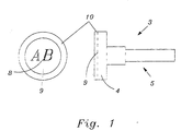
- FIG. 2 shows an anchor rail 1 for construction technology with a visible rail interior 7 Rail part and at intervals from each other on the Rail part 2 attached anchors 3, the anchor 3rd an anchor foot 4 and one smaller in cross-section than the anchor foot 4 Have anchor shaft 5 (see also Fig. 1).
- the anchors 3 are on the rail part in the Rail part 2 holes 6 penetrating them fixed.
- the anchor base 4 lies on the inside of the rail Rail part 2 on.
- FIG. 2 shows that the anchor 4 a marking visible on the inside of the rail 8 carries.
- the anchor base 4 is in the form of a bolt head having.
- the anchor foot 4 has one to the rail interior 7 facing end face 9, which the marking 8 wearing.
- the end face 9 is essentially circular and immediately adjacent to the circumference the end face 9 carries one in the axial direction of the armature 3 protruding ring 10.
- the anchor foot 4 or the end face 9 basically each can have any other geometry, for example Barrel shape by separating two opposite one another Parts from a cylindrical anchor base 4 along secant lines. Even the end faces be concave or convex. In the former case is a design similar to the embodiment with a ring in front.
- the labeling 8 within the ring 10 on the end face 9 attached and the symbols of marking 8 are over the end face 9 lying in the ring is raised.
Landscapes
- Engineering & Computer Science (AREA)
- Physics & Mathematics (AREA)
- Architecture (AREA)
- General Physics & Mathematics (AREA)
- Civil Engineering (AREA)
- Structural Engineering (AREA)
- Electromagnetism (AREA)
- Theoretical Computer Science (AREA)
- Finger-Pressure Massage (AREA)
- Adornments (AREA)
- Road Signs Or Road Markings (AREA)
- Joining Of Building Structures In Genera (AREA)
- Footwear And Its Accessory, Manufacturing Method And Apparatuses (AREA)
Applications Claiming Priority (2)
| Application Number | Priority Date | Filing Date | Title |
|---|---|---|---|
| DE29903167U DE29903167U1 (de) | 1999-02-16 | 1999-02-16 | Ankerschiene mit schieneninnenseitig einsehbarer Kennzeichnung |
| DE29903167U | 1999-02-16 |
Publications (2)
| Publication Number | Publication Date |
|---|---|
| EP1029993A2 true EP1029993A2 (fr) | 2000-08-23 |
| EP1029993A3 EP1029993A3 (fr) | 2002-02-13 |
Family
ID=8069779
Family Applications (1)
| Application Number | Title | Priority Date | Filing Date |
|---|---|---|---|
| EP00250041A Withdrawn EP1029993A3 (fr) | 1999-02-16 | 2000-02-09 | Rail d'ancrage avec marquage visible dans le rail |
Country Status (2)
| Country | Link |
|---|---|
| EP (1) | EP1029993A3 (fr) |
| DE (1) | DE29903167U1 (fr) |
Cited By (4)
| Publication number | Priority date | Publication date | Assignee | Title |
|---|---|---|---|---|
| EP1327729A1 (fr) * | 2002-01-10 | 2003-07-16 | Metka, Gesellschaft m.b.H. | Poutres en treillis pour construire des estrades, des échafaudages ou similaires |
| WO2007036307A1 (fr) * | 2005-09-23 | 2007-04-05 | Neuhäuser GmbH | Trace de rails compose de differents joints de rails |
| US20190226200A1 (en) * | 2018-01-20 | 2019-07-25 | Friedrich Wilhelm Neikes | Profiled rail with plug for fastening to formwork |
| WO2023110458A1 (fr) * | 2021-12-16 | 2023-06-22 | Fischerwerke Gmbh & Co. Kg | Système de rail et procédé de test de celui-ci |
Families Citing this family (1)
| Publication number | Priority date | Publication date | Assignee | Title |
|---|---|---|---|---|
| WO2026052312A1 (fr) * | 2024-09-04 | 2026-03-12 | Fischerwerke Gmbh & Co. Kg | Poinçon de rivet pour un processus de rivetage par fluage radial, procédé de rivetage par fluage radial, dispositif de rivetage par fluage radial, rail d'ancrage et procédé de production du rail d'ancrage |
Citations (2)
| Publication number | Priority date | Publication date | Assignee | Title |
|---|---|---|---|---|
| DE2631396B1 (de) | 1976-07-13 | 1977-07-07 | Karlheinz Dipl-Ing Beine | In ein bauteil einbettbare ankerschiene mit verankerungselementen |
| EP0226710B1 (fr) | 1985-12-24 | 1990-06-06 | Halfeneisen GmbH & Co. Kommanditgesellschaft | Rail d'ancrage pour la technique du bâtiment |
Family Cites Families (3)
| Publication number | Priority date | Publication date | Assignee | Title |
|---|---|---|---|---|
| DE3407801C1 (de) * | 1984-03-02 | 1985-06-20 | Siegfried 7135 Wiernsheim Fricker | Ankerschiene |
| US5511917A (en) * | 1995-05-11 | 1996-04-30 | Dickson Weatherproof Nail Co. | Fastener with graphic indicator of dimensions and method for graphically indicating fastener dimensions |
| GB9525880D0 (en) * | 1995-12-19 | 1996-02-21 | Limited | Channel |
-
1999
- 1999-02-16 DE DE29903167U patent/DE29903167U1/de not_active Expired - Lifetime
-
2000
- 2000-02-09 EP EP00250041A patent/EP1029993A3/fr not_active Withdrawn
Patent Citations (2)
| Publication number | Priority date | Publication date | Assignee | Title |
|---|---|---|---|---|
| DE2631396B1 (de) | 1976-07-13 | 1977-07-07 | Karlheinz Dipl-Ing Beine | In ein bauteil einbettbare ankerschiene mit verankerungselementen |
| EP0226710B1 (fr) | 1985-12-24 | 1990-06-06 | Halfeneisen GmbH & Co. Kommanditgesellschaft | Rail d'ancrage pour la technique du bâtiment |
Cited By (5)
| Publication number | Priority date | Publication date | Assignee | Title |
|---|---|---|---|---|
| EP1327729A1 (fr) * | 2002-01-10 | 2003-07-16 | Metka, Gesellschaft m.b.H. | Poutres en treillis pour construire des estrades, des échafaudages ou similaires |
| WO2007036307A1 (fr) * | 2005-09-23 | 2007-04-05 | Neuhäuser GmbH | Trace de rails compose de differents joints de rails |
| US20190226200A1 (en) * | 2018-01-20 | 2019-07-25 | Friedrich Wilhelm Neikes | Profiled rail with plug for fastening to formwork |
| US10570610B2 (en) * | 2018-01-20 | 2020-02-25 | Friedrich Wilhelm Neikes | Profiled rail with plug for fastening to formwork |
| WO2023110458A1 (fr) * | 2021-12-16 | 2023-06-22 | Fischerwerke Gmbh & Co. Kg | Système de rail et procédé de test de celui-ci |
Also Published As
| Publication number | Publication date |
|---|---|
| DE29903167U1 (de) | 1999-05-27 |
| EP1029993A3 (fr) | 2002-02-13 |
Similar Documents
| Publication | Publication Date | Title |
|---|---|---|
| EP0487890B1 (fr) | Jonction d'élément, en particulier d'un joint à brides | |
| EP2720907B1 (fr) | Dispositif de fixation comprenant un compensateur de tolérance | |
| EP0999912B1 (fr) | Dispositif de separation par rupture d'une piece annulaire | |
| DE69300481T2 (de) | Führungselement eines verschiebbaren sattels für scheibenbremse. | |
| DE19829955A1 (de) | Verbinder zur Verwendung in einer Kupplungsvorrichtung | |
| DE19701857C2 (de) | Geschlitzter Befestigungsring | |
| WO2013029645A1 (fr) | Procédé et dispositif pour fixer une pièce sur une partie de machine rotative | |
| EP3084236B1 (fr) | Dispositif de fixation | |
| DE10142561B4 (de) | Setzgerät mit Nagelmagazin | |
| DE3425079A1 (de) | Mit einer welle verbundener koerper | |
| EP1029993A2 (fr) | Rail d'ancrage avec marquage visible dans le rail | |
| EP1080802A2 (fr) | Dispositif de fixation dans un outil pour un procédé d' hydroformage | |
| DE3436733C2 (fr) | ||
| DE19912068B4 (de) | Wellen- oder Stellmutter und Verfahren zu ihrer Herstellung | |
| EP0591507A1 (fr) | Element d'assemblage par serrage du type rivet borgne | |
| DE10142438B4 (de) | Befestigungsanordnung für einen Schaftmeißel | |
| DE19907475C1 (de) | Ankerschiene für die Bautechnik mit mittels Abstreifkragen fixierten Ankern | |
| DE69421869T2 (de) | Rollaufweitwerkzeug | |
| DE8904751U1 (de) | Aufweitvorrichtung für geschlitzte Klemmbohrungen | |
| WO2003004832A1 (fr) | Systeme de fixation pour outil de coupe | |
| DE60121338T2 (de) | Verfahren und vorrichtung zum befestigen eines kolbens oder einer kolbenstangeverbindung an einer kolbenstange | |
| EP0391228A2 (fr) | Dispositif de montage pour embrayages à disque de véhicule | |
| DE4404698A1 (de) | Spreizdübel | |
| DE4318615A1 (de) | Vorrichtung und Verfahren zum stirnseitigen Verbinden eines profilierten Bauelementes, insbesondere eines Rohres, mit einem anderen Element | |
| EP0568000B1 (fr) | Cheville |
Legal Events
| Date | Code | Title | Description |
|---|---|---|---|
| PUAI | Public reference made under article 153(3) epc to a published international application that has entered the european phase |
Free format text: ORIGINAL CODE: 0009012 |
|
| AK | Designated contracting states |
Kind code of ref document: A2 Designated state(s): AT BE CH CY DE DK ES FI FR GB GR IE IT LI LU MC NL PT SE |
|
| AX | Request for extension of the european patent |
Free format text: AL;LT;LV;MK;RO;SI |
|
| PUAL | Search report despatched |
Free format text: ORIGINAL CODE: 0009013 |
|
| AK | Designated contracting states |
Kind code of ref document: A3 Designated state(s): AT BE CH CY DE DK ES FI FR GB GR IE IT LI LU MC NL PT SE |
|
| AX | Request for extension of the european patent |
Free format text: AL;LT;LV;MK;RO;SI |
|
| AKX | Designation fees paid | ||
| REG | Reference to a national code |
Ref country code: DE Ref legal event code: 8566 |
|
| STAA | Information on the status of an ep patent application or granted ep patent |
Free format text: STATUS: THE APPLICATION IS DEEMED TO BE WITHDRAWN |
|
| 18D | Application deemed to be withdrawn |
Effective date: 20020814 |