EP1029994A2 - Ankerschiene für die Bautechnik mit mittels Abstreifkragen fixierten Ankern - Google Patents
Ankerschiene für die Bautechnik mit mittels Abstreifkragen fixierten Ankern Download PDFInfo
- Publication number
- EP1029994A2 EP1029994A2 EP00250042A EP00250042A EP1029994A2 EP 1029994 A2 EP1029994 A2 EP 1029994A2 EP 00250042 A EP00250042 A EP 00250042A EP 00250042 A EP00250042 A EP 00250042A EP 1029994 A2 EP1029994 A2 EP 1029994A2
- Authority
- EP
- European Patent Office
- Prior art keywords
- anchor
- rail
- shaft
- foot
- rail part
- Prior art date
- Legal status (The legal status is an assumption and is not a legal conclusion. Google has not performed a legal analysis and makes no representation as to the accuracy of the status listed.)
- Withdrawn
Links
- 238000004873 anchoring Methods 0.000 title description 3
- 238000009435 building construction Methods 0.000 title 1
- 238000007790 scraping Methods 0.000 title 1
- 238000004519 manufacturing process Methods 0.000 claims abstract description 6
- 239000000463 material Substances 0.000 claims description 15
- 238000000034 method Methods 0.000 claims description 7
- 230000015572 biosynthetic process Effects 0.000 claims description 5
- 238000005516 engineering process Methods 0.000 claims description 5
- 238000005755 formation reaction Methods 0.000 claims description 5
- 238000010276 construction Methods 0.000 claims description 4
- 230000000284 resting effect Effects 0.000 claims 1
- 230000006835 compression Effects 0.000 description 4
- 238000007906 compression Methods 0.000 description 4
- 230000000052 comparative effect Effects 0.000 description 3
- 238000002372 labelling Methods 0.000 description 2
- 238000005056 compaction Methods 0.000 description 1
- 238000010835 comparative analysis Methods 0.000 description 1
- 230000007797 corrosion Effects 0.000 description 1
- 238000005260 corrosion Methods 0.000 description 1
- 230000006378 damage Effects 0.000 description 1
- ZINJLDJMHCUBIP-UHFFFAOYSA-N ethametsulfuron-methyl Chemical compound CCOC1=NC(NC)=NC(NC(=O)NS(=O)(=O)C=2C(=CC=CC=2)C(=O)OC)=N1 ZINJLDJMHCUBIP-UHFFFAOYSA-N 0.000 description 1
- 230000002265 prevention Effects 0.000 description 1
- 238000007493 shaping process Methods 0.000 description 1
Images


Classifications
-
- E—FIXED CONSTRUCTIONS
- E04—BUILDING
- E04B—GENERAL BUILDING CONSTRUCTIONS; WALLS, e.g. PARTITIONS; ROOFS; FLOORS; CEILINGS; INSULATION OR OTHER PROTECTION OF BUILDINGS
- E04B1/00—Constructions in general; Structures which are not restricted either to walls, e.g. partitions, or floors or ceilings or roofs
- E04B1/38—Connections for building structures in general
- E04B1/41—Connecting devices specially adapted for embedding in concrete or masonry
- E04B1/4107—Longitudinal elements having an open profile, with the opening parallel to the concrete or masonry surface, i.e. anchoring rails
Definitions
- the invention relates to an anchor rail for construction technology with one rail part and at intervals from each other anchors attached to the rail part, whereby the anchors one anchor foot and one opposite the Have anchoring shank with a smaller cross-section, the anchors on the rail part in in the Holes made through the rail part through these are fixed, with the anchor foot inside the rail rests on the rail part and the anchor shaft one lying on the outside of the rail on the rail part Has captive security.
- - anchor channels for the Construction technology is manufactured by the meter, with the Anchors can be detached or fixed, but cannot be lost with the Rail part are connected.
- the rail part has in usually, but not mandatory, essentially one C- or U-shaped cross-section perpendicular to the longitudinal extension of the rail part.
- the anchors are in this case usually connected to the back of the rail.
- the both legs of the rail part leave a gap free, the width of which is such that an anchor foot can be passed through.
- the anchor foot do not fit through the hole in the rail part may.
- the diameter of the anchor shaft the anchor foot is the same or slightly smaller than the diameter of the hole in the rail part his.
- the distances between two anchors are for example 250 mm.
- Anchor channels of the structure mentioned at the beginning are, for example from references DE 25 31 396 C1 and EP 0 226 710 B1.
- the anchor channels are fixed by that the anchor shaft with a fixed anchor base with a Clamping tool gripped at a distance from the rail part and moves it towards the anchor foot and thus a shaft part adjacent to the rail part is compressed becomes.
- the result is the anchor on the one hand shortened and on the other hand by means of the outside of the rail attached, as it were squeezed material.
- a structural change occurs during compression, in particular Microstructure compression.
- These well-known anchor channels have several disadvantages. First of all it is complex to carry out a compression.
- the invention is the technical problem to create an anchor rail, in which the anchors with less effort on the rail part are fixable and also the tensile strength of the anchor remains essentially unchanged or preserved.
- a scraper collar is a loss protection, which by essentially cutting Material shaping is formed from the shaft.
- the circumference of the shaft is by means of a Cutting tool a thin outer layer of the shaft peeled off towards the rail part, until at least part of the peeled off or stripped material on the outside of the rail comes to the concern.
- the core of the shaft remains here practically unchanged, especially occurs practically no structural change.
- the one stripping Scraper collar formed is of a comparative nature as such low strength, this strength is however, it is completely sufficient to protect against loss to fulfill.
- the holes are convex on the outside of the rail Formations of the rail part arranged, preferably arranged concentrically to the formations.
- the holes usually have in the rail part a substantially cylindrical cross section. Accordingly, the anchor shaft is orthogonal to Longitudinal extension of the anchor a circular cross-section, the diameter of the anchor shaft then to the anchor base preferably slightly is smaller than the diameter of the hole. Basically the invention is also for holes and anchor shafts with other cross sections, for example rectangular cross section, can be used.
- the process of stripping can vary widely Ways take place as long as stripping continuously stripped or cut material or at least in the final phase of stripping stripped material not separated from the shaft core becomes. In any case, at least in the final phase of the Stripping so much material connected to the shaft core remain that a functioning as loss prevention Scraper collar connected to the shaft core remains.
- the invention is characterized in that the Scraper collar from a before fixing the anchor compared to a second shaft part larger in diameter first shaft part of the anchor shaft is formed.
- the first shaft part preferably closes immediately to the anchor foot. Then it needs Cutting tool only in the direction of the longitudinal extent the anchor shaft are moved, material from the the first shaft part is stripped.
- the inside diameter of the cutting tool between the diameters of the first and second Part of the shaft. In this case, the cross sections the hole in the rail part and the first shaft part practically congruent.
- the anchor typically has an anchor head.
- the anchor head can be attached in a variety of ways his.
- the second shaft part have an external thread on which one the anchor head forming nut is screwed on. Can too the anchor head is welded onto the second shaft part become.
- the Anchor head from the second shaft part by means of wobble riveting is formed.
- the striking tool is on the protruding from the rivet bed End of the shaft due to plastic material deformation an anchor head is formed.
- the striking tool guides with one orthogonal to the shaft axis Level with an angle ⁇ 90 °, preferably between 1 ° and 20 °, most preferably 2 ° to 10 °, for example 5 °, angled striking surface a rotationally symmetrical Precession movement running to the shaft axis out.
- the precession movement can additionally a rocking movement around a workpiece Swing axis be superimposed.
- the cutting tool also the rivet bed at the same time Wear the anchor head.
- the rivet bed lies then the cutting element in the axial direction of the anchor shaft across from.
- Essential feature of wobble riveting is that the striking tool on a workpiece surface is passed on and practically no "smearing" of the material takes place.
- the wobble riveting has the advantage that the required pressure forces or the opposite support staff compared to other techniques are considerably smaller. In this respect, both the Fixing the anchor as well as the design of the anchor head with relatively little elaborate design and operated devices.
- the anchor foot carries a label. This is already before the anchor is fixed to the Rail part attached to the anchor and can be any Be kind; however, labeling is preferred to be embossed (raised or deepened). Such labels are mandatory. in the Within the scope of the invention it is possible to use the labeling on the anchor base during the manufacture of the anchor to attach, as the when stripping or if necessary wobble rivets forces occurring to support the Anchor feet are so small that the marking is not is destroyed, for example by equalization.
- the Anchor foot can adjoin the perimeter on the strinside wear a support ring which is sufficient to prevent Pressure forces of processing when fixing and to pick up when tumbling. With such a ring even the most delicate markings in front of one Equalization or destruction protected.
- the invention also teaches a method of manufacture an anchor rail, an anchor with an anchor foot and an anchor shaft from the inside of one Part of the rail with the anchor shaft through a hole in the rail part is inserted, the anchor foot on the inside of the rail against the rail part brought and held there, with the outside of the rail and spaced from the rail part
- Anchor shaft comprehensive cutting tool set up is and wherein the cutting tool relative to the Anchor foot is moved towards the anchor foot and in the course of the movement of the anchor shaft, one on the outside of the rail wiper collar attached to the rail part forming, material is stripped.
- the Anchor shaft can be orthogonal to its longitudinal extension have a circular cross section, the Anchor shaft adjoining the anchor foot and compared to a second shaft part larger in diameter has the first shaft part. After stripping the Scraper collar at the outside of the shin Anchoring can be done by wobble riveting an anchor head be shaped.
- the holes 6 are protruding in a convex manner on the outside of the rail Formations 8 concentrically of the rail part 2 arranged.
- the holes 6 in the rail part 2 have a substantially cylindrical cross section on.
- the anchor shaft 5 points orthogonally to the longitudinal extent the armature 3 has a circular cross section on.
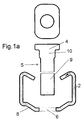
- the scraper collar 7 is made before a fixation of the armature 3 relative to a second shaft part 9 diameter larger first shaft part 10 of the anchor shaft 5 formed (Fig. 1a-d).
- the anchor head 11 is from the second shaft part 9 by way of wobble riveting molded (Fig. 2a-c).
- the anchor 3 is from the inside a rail part 2 with the anchor shaft 5 by the Hole 6 inserted into the rail part 2 (Fig. 1a and 1b).
- the anchor foot 4 is on the inside of the rail brought the rail part 2 into contact and held there. Outside of the rail and spaced from it Rail part 2 then becomes an anchor shaft 5 Cutting tool 12 with tool jaws 13 and in the cutting plates 14 mounted on the tool jaws 13 established (Fig. 1c).
- the cutting plates 14 form essentially a circular opening, at whose the Anchor foot 5 facing edge cutting arranged are.
- the cutting edges form a circle, the Diameter larger than the diameter of the second Shaft part 9, but smaller than the diameter of the first shaft part 10 (see also FIG. 3).
- FIG. 2c A comparative view of Figures 2a-c is removable that after stripping the scraper 7 at your shank outside end of the anchor shaft 5 an anchor head 11 by means of wobble riveting is formed.
- the second shaft part 9 of a tool which is preferably a coaxial concave to anchor shaft 5, for example bowl-shaped, rivet bed 15, collected and by means of a drive in the axial direction towards the rivet bed 15
- Döpperwerkzeuges 16 is from the Rivet bed protruding shaft end due to plastic material deformation an anchor head 11 is formed.
- the Döpperwerkmaschine 16 leads with one against one Shaft axis orthogonal plane with an angle of 15 ° angled striking surface 17 a rotationally symmetrical Precession movement running to the shaft axis out.
- the figures also show that the cutting tool 12 also the rivet bed at the same time 15 for manufacturing the anchor head 11 carries.
- the rivet bed 15 is the cutting plates 14 in the axial direction the anchor shaft 5 opposite. Finally be the tool jaws 13 moved away (
Landscapes
- Engineering & Computer Science (AREA)
- Architecture (AREA)
- Physics & Mathematics (AREA)
- Electromagnetism (AREA)
- Civil Engineering (AREA)
- Structural Engineering (AREA)
- Joining Of Building Structures In Genera (AREA)
- Insertion Pins And Rivets (AREA)
Abstract
Description
- Figuren 1a-d:
- die Arbeitsfolgen der Herstellung eines Abstreifkragens,
- Figuren 2a-c:
- die an die Arbeitsfolgen der Figuren 1a-d anschließenden Arbeitsfolgen der Herstellung eines Ankerkopfes und
- Figur 3:
- Eine Ansicht des Schneidwerkzeuges in der Ebene A-A der Figur 1c.
Claims (10)
- Ankerschiene (1) für die Bautechnik mit einem Schienenteil (2) und in Abständen voneinander an dem Schienenteil (2) angebrachten Ankern (3), wobei die Anker (3) einen Ankerfuß (4) und einen gegenüber dem Ankerfuß (4) querschnittskleineren Ankerschaft (5) aufweisen, wobei die Anker (3) an dem Schienenteil (2) in in dem Schienenteil (2) angebrachten Löchern (6) diese durchgreifend fixiert sind, wobei der Ankerfuß (4) schieneninnenseitig an dem Schienenteil (2) anliegt und wobei der Ankerschaft (5) eine schienenaußenseitig an dem Schienenteil (2) anliegende Verliersicherung aufweist,
dadurch gekennzeichnet,
daß die Verliersicherung aus einem aus dem Ankerschaft (5) ausgebildeten Abstreifkragen (7) gebildet ist. - Ankerschiene (1) nach Anspruch 1, dadurch gekennzeichnet, daß die Löcher (6) in schienenaußenseitig konvex vorstehenden Ausformungen (8) des Schienenteils (2) angeordnet, vorzugsweise konzentrisch zu den Ausformungen (8) angeordnet, sind.
- Ankerschiene nach Anspruch 1 oder 2, dadurch gekennzeichnet, daß die Löcher (6) in dem Schienenteil (2) einen im wesentlichen zylindrischen Querschnitt aufweisen.
- Ankerschiene (1) nach einem der Ansprüche 1 bis 3, dadurch gekennzeichnet, daß der Ankerschaft (5) orthogonal zur Längserstreckung des Ankers (3) einen kreisförmigen Querschnitt aufweist und daß der Abstreifkragen (7) aus einem vor der Fixierung des Ankers (3) gegenüber einem zweiten Schaftteil (9) durchmessergrößeren ersten Schaftteil (10) des Ankerschafts (5) ausgebildet ist.
- Ankerschiene (1) nach einem der Ansprüche 1 bis 4, dadurch gekennzeichnet, daß die Anker (3) einen Ankerkopf (11) aufweisen.
- Ankerschiene (1) nach einem der Ansprüche 1 bis 5, dadurch gekennzeichnet, daß der Ankerkopf (11) aus dem zweiten Schaftteil (9) im Wege des Taumelnietens ausgeformt ist.
- Ankerschiene (1) nach einem der Ansprüche 1 bis 6, dadurch gekennzeichnet, daß der Ankerfuß (4) eine Kennzeichnung trägt, wobei die Kennzeichnung vorzugsweise schieneninnenraumseitig einsehbar ist, höchstvorzugsweise stirnseitig am Ankerfuß (4) angebracht ist.
- Verfahren zur Herstellung einer Ankerschiene (1),
wobei ein Anker (3) mit einem Ankerfuß (4) und einem Ankerschaft (5) von der Innenseite eines Schienenteils (2) mit dem Ankerschaft (5) durch ein Loch (6) in dem Schienenteil (2) eingesteckt wird,
wobei der Ankerfuß (4) schieneninnenseitig an das Schienenteil (2) zum Anliegen gebracht und dort gehalten wird,
wobei schienenaußenseitig und beabstandet von dem Schienenteil (2) ein den Ankerschaft (5) umfassendes Schneidwerkzeug (12) eingerichtet wird und
wobei das Schneidwerkzeug (12) relativ zu dem Ankerfuß (4) in Richtung auf den Ankerfuß (4) bewegt wird und im Zuge der Bewegung von dem Ankerschaft (5), einen schienenaußenseitig an dem Schienenteil (2) anliegenden Abstreifkragen (7) bildend, Material abgestreift wird. - Verfahren nach Anspruch 8, wobei der Ankerschaft (5) orthogonal zu seiner Längserstreckung einen kreisförmigen Querschnitt aufweist, wobei der Ankerschaft (5) ein an den Ankerfuß (4) anschließenden und gegenüber einem zweiten Schaftteil (9) durchmessergrößeren ersten Schaftteil (10) aufweist.
- Verfahren nach Anspruch 8 oder 9, wobei nach dem Abstreifen des Abstreifkragens (7) an dem scheinenaußenseitigen Ende des Ankerschafts (5) im Wege des Taumelnietens ein Ankerkopf (11) ausgeformt wird.
Applications Claiming Priority (2)
| Application Number | Priority Date | Filing Date | Title |
|---|---|---|---|
| DE1999107475 DE19907475C1 (de) | 1999-02-16 | 1999-02-16 | Ankerschiene für die Bautechnik mit mittels Abstreifkragen fixierten Ankern |
| DE19907475 | 1999-02-16 |
Publications (2)
| Publication Number | Publication Date |
|---|---|
| EP1029994A2 true EP1029994A2 (de) | 2000-08-23 |
| EP1029994A3 EP1029994A3 (de) | 2002-02-13 |
Family
ID=7898382
Family Applications (1)
| Application Number | Title | Priority Date | Filing Date |
|---|---|---|---|
| EP00250042A Withdrawn EP1029994A3 (de) | 1999-02-16 | 2000-02-09 | Ankerschiene für die Bautechnik mit mittels Abstreifkragen fixierten Ankern |
Country Status (2)
| Country | Link |
|---|---|
| EP (1) | EP1029994A3 (de) |
| DE (1) | DE19907475C1 (de) |
Families Citing this family (4)
| Publication number | Priority date | Publication date | Assignee | Title |
|---|---|---|---|---|
| DE102015008226A1 (de) | 2015-06-29 | 2016-12-29 | JORDAHL GmbH | Stahlbetonbauelement mit netzförmigem Armierungselement |
| EP3124711A1 (de) | 2015-07-29 | 2017-02-01 | HILTI Aktiengesellschaft | Herstellungsverfahren für eine ankerschiene sowie ankerschiene |
| DE102018101251A1 (de) | 2018-01-20 | 2019-07-25 | Friedrich Wilhelm Neikes | Profilschiene mit Stopfen zur Befestigung auf einer Verschalung |
| WO2026052312A1 (de) * | 2024-09-04 | 2026-03-12 | Fischerwerke Gmbh & Co. Kg | Nietstempel zum taumelnieten, verfahren zum taumelnieten, vorrichtung zum taumelnieten, ankerschiene, verfahren zur herstellung der ankerschiene |
Citations (2)
| Publication number | Priority date | Publication date | Assignee | Title |
|---|---|---|---|---|
| DE2631396B1 (de) | 1976-07-13 | 1977-07-07 | Karlheinz Dipl-Ing Beine | In ein bauteil einbettbare ankerschiene mit verankerungselementen |
| EP0226710B1 (de) | 1985-12-24 | 1990-06-06 | Halfeneisen GmbH & Co. Kommanditgesellschaft | Ankerschiene für die Bautechnik |
Family Cites Families (5)
| Publication number | Priority date | Publication date | Assignee | Title |
|---|---|---|---|---|
| DE8708531U1 (de) * | 1986-08-14 | 1987-12-10 | Halfeneisen GmbH & Co KG, 4000 Düsseldorf | Ankerschiene mit gestauchtem Ankerbolzenkopf |
| DE3918044A1 (de) * | 1989-06-02 | 1990-12-06 | Halfeneisen Gmbh & Co Kg | Ankerschiene fuer die bautechnik |
| US5511917A (en) * | 1995-05-11 | 1996-04-30 | Dickson Weatherproof Nail Co. | Fastener with graphic indicator of dimensions and method for graphically indicating fastener dimensions |
| PT758039E (pt) * | 1995-07-26 | 2001-06-29 | Halfen Gmbh & Co Kg | Calha de ancoragem para a construcao civil |
| DE59609402D1 (de) * | 1995-12-19 | 2002-08-08 | Ahlmann Aco Severin | Verriegelungsbolzen |
-
1999
- 1999-02-16 DE DE1999107475 patent/DE19907475C1/de not_active Expired - Lifetime
-
2000
- 2000-02-09 EP EP00250042A patent/EP1029994A3/de not_active Withdrawn
Patent Citations (2)
| Publication number | Priority date | Publication date | Assignee | Title |
|---|---|---|---|---|
| DE2631396B1 (de) | 1976-07-13 | 1977-07-07 | Karlheinz Dipl-Ing Beine | In ein bauteil einbettbare ankerschiene mit verankerungselementen |
| EP0226710B1 (de) | 1985-12-24 | 1990-06-06 | Halfeneisen GmbH & Co. Kommanditgesellschaft | Ankerschiene für die Bautechnik |
Also Published As
| Publication number | Publication date |
|---|---|
| EP1029994A3 (de) | 2002-02-13 |
| DE19907475C1 (de) | 2000-12-28 |
Similar Documents
| Publication | Publication Date | Title |
|---|---|---|
| DE4420073C2 (de) | Nutenstein | |
| DE19902461B4 (de) | Mutter mit T-förmigem Querschnitt | |
| DE2012966A1 (de) | Blindbefestigungsmittel | |
| DE3448086C2 (de) | ||
| DE2709830A1 (de) | Bohrer und verfahren zu seiner herstellung | |
| DE1954414A1 (de) | Befestigungselement | |
| DD140239A5 (de) | Antriebselement und verfahren sowie vorrichtung zur herstellung desselben | |
| DE1955606A1 (de) | Durchsteckmutter und Vorrichtung sowie Verfahren zum Einsetzen der Mutter | |
| DE2031012A1 (de) | Schraubendreher | |
| DE102006028529B4 (de) | Verfahren und Vorrichtung zum Anbringen einer Verbindungselementmutter an einem hydrogeformten Teil | |
| DE2031024A1 (de) | Kopfschraube | |
| DE102005056378A1 (de) | Verfahren zum Einbringen und Verankern wenigstens eines Verbindungselementes in einem Werkstück sowie Vorrichtung zum Durchführen des Verfahrens | |
| DE102019203051A1 (de) | Befestigungselement zum Reibschweißen sowie Verfahren zum Reibschweißen eines Befestigungselements an ein flächiges Werkstück | |
| DE19907475C1 (de) | Ankerschiene für die Bautechnik mit mittels Abstreifkragen fixierten Ankern | |
| DE2615322C2 (de) | Befestigungsvorrichtung für Türschilder bzw. Türrosetten | |
| DE69009310T2 (de) | Klemmvorrichtung zur Herstellung von Nägeln. | |
| DE1814847A1 (de) | Abstreifvorrichtung | |
| CH691578A5 (de) | Spannmutter für eine Spannzange. | |
| DE842729C (de) | Befestigung eines kleinen metallischen Gegenstandes in einem Traeger | |
| EP1029993A2 (de) | Ankerschiene mit schieneninnenseitig einsehbarer Kennzeichnung | |
| DE3423688C2 (de) | ||
| DE2106107A1 (de) | Selbstbohrender Zug Niet | |
| DE2555124A1 (de) | Gewindeverbindung | |
| DE4211482C2 (de) | Markierungsvorrichtung | |
| DE2744660A1 (de) | Drahtseilendanschlusstueck |
Legal Events
| Date | Code | Title | Description |
|---|---|---|---|
| PUAI | Public reference made under article 153(3) epc to a published international application that has entered the european phase |
Free format text: ORIGINAL CODE: 0009012 |
|
| AK | Designated contracting states |
Kind code of ref document: A2 Designated state(s): AT BE CH CY DE DK ES FI FR GB GR IE IT LI LU MC NL PT SE |
|
| AX | Request for extension of the european patent |
Free format text: AL;LT;LV;MK;RO;SI |
|
| PUAL | Search report despatched |
Free format text: ORIGINAL CODE: 0009013 |
|
| AK | Designated contracting states |
Kind code of ref document: A3 Designated state(s): AT BE CH CY DE DK ES FI FR GB GR IE IT LI LU MC NL PT SE |
|
| AX | Request for extension of the european patent |
Free format text: AL;LT;LV;MK;RO;SI |
|
| AKX | Designation fees paid | ||
| REG | Reference to a national code |
Ref country code: DE Ref legal event code: 8566 |
|
| STAA | Information on the status of an ep patent application or granted ep patent |
Free format text: STATUS: THE APPLICATION IS DEEMED TO BE WITHDRAWN |
|
| 18D | Application deemed to be withdrawn |
Effective date: 20020814 |