EP1030471B1 - Système de transmission optique régénéré WDM - Google Patents
Système de transmission optique régénéré WDM Download PDFInfo
- Publication number
- EP1030471B1 EP1030471B1 EP00400174A EP00400174A EP1030471B1 EP 1030471 B1 EP1030471 B1 EP 1030471B1 EP 00400174 A EP00400174 A EP 00400174A EP 00400174 A EP00400174 A EP 00400174A EP 1030471 B1 EP1030471 B1 EP 1030471B1
- Authority
- EP
- European Patent Office
- Prior art keywords
- channels
- regenerator
- optical
- channel
- regenerated
- Prior art date
- Legal status (The legal status is an assumption and is not a legal conclusion. Google has not performed a legal analysis and makes no representation as to the accuracy of the status listed.)
- Expired - Lifetime
Links
- 230000003287 optical effect Effects 0.000 title claims abstract description 53
- 230000005540 biological transmission Effects 0.000 title claims abstract description 26
- 239000013307 optical fiber Substances 0.000 claims abstract description 8
- 238000000034 method Methods 0.000 claims abstract description 4
- 230000001360 synchronised effect Effects 0.000 claims description 9
- 230000001172 regenerating effect Effects 0.000 claims description 4
- 239000000835 fiber Substances 0.000 claims description 3
- 230000008929 regeneration Effects 0.000 description 26
- 238000011069 regeneration method Methods 0.000 description 26
- 239000006185 dispersion Substances 0.000 description 4
- 238000000605 extraction Methods 0.000 description 3
- 238000003780 insertion Methods 0.000 description 3
- 230000037431 insertion Effects 0.000 description 3
- 238000010521 absorption reaction Methods 0.000 description 2
- 230000003993 interaction Effects 0.000 description 2
- 238000004519 manufacturing process Methods 0.000 description 2
- 230000005374 Kerr effect Effects 0.000 description 1
- 238000005192 partition Methods 0.000 description 1
- 238000000926 separation method Methods 0.000 description 1
- 238000007493 shaping process Methods 0.000 description 1
- 238000011144 upstream manufacturing Methods 0.000 description 1
Images
Classifications
-
- H—ELECTRICITY
- H04—ELECTRIC COMMUNICATION TECHNIQUE
- H04B—TRANSMISSION
- H04B10/00—Transmission systems employing electromagnetic waves other than radio-waves, e.g. infrared, visible or ultraviolet light, or employing corpuscular radiation, e.g. quantum communication
- H04B10/29—Repeaters
-
- H—ELECTRICITY
- H04—ELECTRIC COMMUNICATION TECHNIQUE
- H04B—TRANSMISSION
- H04B10/00—Transmission systems employing electromagnetic waves other than radio-waves, e.g. infrared, visible or ultraviolet light, or employing corpuscular radiation, e.g. quantum communication
- H04B10/29—Repeaters
- H04B10/291—Repeaters in which processing or amplification is carried out without conversion of the main signal from optical form
- H04B10/293—Signal power control
- H04B10/294—Signal power control in a multiwavelength system, e.g. gain equalisation
-
- H—ELECTRICITY
- H04—ELECTRIC COMMUNICATION TECHNIQUE
- H04B—TRANSMISSION
- H04B10/00—Transmission systems employing electromagnetic waves other than radio-waves, e.g. infrared, visible or ultraviolet light, or employing corpuscular radiation, e.g. quantum communication
- H04B10/29—Repeaters
- H04B10/291—Repeaters in which processing or amplification is carried out without conversion of the main signal from optical form
- H04B10/299—Signal waveform processing, e.g. reshaping or retiming
-
- H—ELECTRICITY
- H04—ELECTRIC COMMUNICATION TECHNIQUE
- H04B—TRANSMISSION
- H04B2210/00—Indexing scheme relating to optical transmission systems
- H04B2210/25—Distortion or dispersion compensation
- H04B2210/258—Distortion or dispersion compensation treating each wavelength or wavelength band separately
Definitions
- the present invention relates to fiber transmission systems wavelength multiplexing optics, and more specifically, the regeneration of these signals.
- regenerators that perform functions of impulse fitness, time cropping of pulses and compensation for losses of intensity of pulses in the regenerator (regeneration called “3R” for "re-shaping", “re-timing” and “re-amplifying” in Anglo-Saxon terminology).
- Transmission systems with wavelength multiplexing include more and more channels (or wavelengths) by optical fiber.
- the throughput per channel also increases.
- the most recent transmission systems transoceanic have a capacity of 32 channels at 10 Gbit / s each.
- Another solution usable in the case of WDM soliton signals (or RZ converted into solitons at the regenerator input), consists in using a regenerator comprising means for compensating chromatic dispersion, for resynchronize the different channels, then a synchronous modulator.
- This solution has the disadvantage of requiring very precise management of the dispersion chromatic, so that the signals are perfectly synchronized as input of the synchronous modulator. Such management of chromatic dispersion is all the more more difficult to realize that it must apply to a large number of channels.
- the invention provides a simple solution for the regeneration of canals in a WDM transmission system, and which remains simple even when the number of channels is important.
- the invention provides a transmission system on optical fiber with wavelength multiplexing with n channels, comprising an optical transmitter and an optical receiver connected by an optical line comprising at least one optical fiber, and at least one set of m (m> 1) means of regenerating the channels, characterized in that p (p ⁇ m) successive means of regenerating respectively regenerate groups of channels G 1 , G 2 , ... G p , these groups forming a partition of all n channels.
- the number p of groups is preferably a submultiple of the total number m of system regenerators.
- Channel groups preferably have a small number of channels, especially a single channel or two channels.
- regenerator is thus greatly simplified, compared solutions consisting in demultiplexing all signals or compensating for the chromatic dispersion of all the signals between them.
- each regenerator comprises a means of optical regeneration.
- each regenerator may include means for synchronizing the channels to regenerate and an optical regeneration means, in particular a modulator synchronous.
- each regenerator includes a demultiplexer and a multiplexer to process independently the channels to be regenerated on the one hand, and the channels not to regenerate on the other hand.
- each regenerator includes an insertion / extraction device to isolate the channels to regenerate.
- a compensation amplifier to compensate for differences in intensity between regenerated channels and channels may not be regenerated.
- the transmission system comprises a supervisory means implementing a dedicated channel ⁇ s .
- each regenerator can comprise a means for separating the channel ⁇ s from the other channels, a supervision unit for modifying the signal of the channel ⁇ s according to information relating to the state of the regenerator, and a means for remultiplexing the channel ⁇ s with the other channels.
- each regenerator may include a means of regeneration to regenerate the channels of a group of channels, the supervisory unit receiving information from said regeneration means and receiving a fraction of the signal regenerated delivered by said regeneration means.
- the system according to the invention comprises a plurality of optical amplifiers arranged at a distance Z o from each other, and optical regenerators arranged at a distance Z r from each other, where Z r is a multiple of Z at.
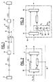
- FIG. 1 shows an optical transmission system of conventional structure. It comprises two terminal stations, namely a transmitter 2 and a receiver 4, connected by a fiber optic link 6. Amplifiers 8 are arranged at regular intervals on this optical fiber to re-amplify the signals and thus compensate for the losses due to the absorption by optical fiber.
- the step Z a between two successive amplifiers depends on many parameters (signal intensity, absorption by the optical fiber, separation in wavelength between the signals, etc.); it is typically 50 to 100 km.
- the transmission system also comprises optical regenerators 10.
- the step Z r between two successive regenerators depends on many parameters (Kerr effect, Gordon-Haus jitter, four-wave interaction, etc.) which affect the shape of the pulses and induce a shift of the pulses with respect to their nominal bit time.
- the regenerators are generally arranged at a distance Z a from an amplifier 10 and include an amplifier similar to amplifiers 8.
- the pitch Z r between two regenerators is equal to kZ a , where k is an integer generally between 5 and 10, this number depending in particular on the bit rate of the multiplex signals.
- each regenerator regenerates a reduced number of channels.
- each regenerator could be designed to regenerate a single length of wave.
- the n channels are distributed into n groups G 1 , G 2 , ..., G n each comprising a single channel.
- each regenerator There will thus be successively along the line, with intervals Z r between each regenerator, a regenerator R 1 to regenerate the channel ⁇ 1 , a regenerator R 2 for the channel ⁇ 2 , ..., a regenerator R n for the channel ⁇ n , again a regenerator R 1 for the channel ⁇ 1 , etc.
- the important advantage is the simplification brought to the system because each regenerator has a simple structure.
- n channels are divided into n / 2 groups, comprising each two channels, and more generally a system in which the n channels are divided into p groups each with n / p channels.
- each regenerator has an identical structure. This results in greater simplicity of design of the system and manufacturing of regenerators, which leads to greater reliability of the transmission system.
- the distance Z a between amplifiers is of the order of 40 km and the distance Z r between regenerators of the order of 320 km.
- FIG. 2 illustrates a first embodiment of a regenerator designed to regenerate a single channel. It includes at the input a duplexer 12 to separate the channel to be regenerated ⁇ k from the other channels ⁇ i (1 ⁇ i ⁇ n; i ⁇ k), and at the output a duplexer 14 for remultiplexing the channel ⁇ k with the other channels.
- the regeneration means 16 can be of any known type, and advantageously comprise, in the case of soliton or RZ signals converted into solitons, a synchronous optical modulator.
- opto-electric regeneration means that is to say regeneration means in which the optical signals are converted into electrical signals, then regenerated in electrical form, before being again converted into optical signals, is not excluded in the context of the present invention.
- the regeneration means is supplied by an electric cable 18 (not shown in Figure 1).
- a compensation amplifier 20 can be placed on the branch of the regenerator receiving the non-regenerated channels.
- such a compensation amplifier could on the contrary be placed on the branch receiving the regeneration means 16, in the case where the latter induces a loss of intensity in the channel ⁇ k .
- the regenerator 10 of FIG. 2 further comprises an amplifier 8. This is preferably placed at the outlet of the regenerator 10, but it could also be arranged at the inlet of the latter. It could also replace the amplifier 20 of FIG. 2, as regards the non-regenerated channels.
- the regeneration means 16 should also include an amplifier for bringing the signals to be regenerated to the same intensity, at the output of the regenerator 10, as that of the non-regenerated signals. This latter arrangement is particularly interesting since the number of signals which each amplifier must amplify is lower, compared to the line amplifiers 8 (FIG. 1). We can then use, in regenerators, less powerful amplifiers or have more power margin.
- FIG. 3 illustrates an embodiment similar to that of FIG. 2, but adapted to the regeneration of two channels ⁇ k and ⁇ k + 1 .
- the only difference with the regenerator of Figure 2 is to provide a synchronization means 22 upstream of the regeneration means 16, to synchronize the two channels to be regenerated.
- Such synchronization means can be obtained simply, as shown, using an optical circulator with three ports 24 and a delay line 26 comprising two optical reflectors, for example Bragg filters 28, 30 spaced apart. from one another such that the channels are resynchronized when they are received in the regeneration means 16.
- the delay between the channels can be adjusted using an adjustable delay line 32.
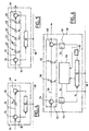
- FIG. 4 illustrates a second embodiment of a regenerator designed to regenerate a single channel. It essentially comprises an insertion / extraction device 33, conventional in the technical field of optical transmission systems, and a regeneration means 16.
- the extraction insertion device 33 comprises a first optical circulator with three ports 34, a section of optical line 36 provided with an optical reflector 38, for example a Bragg filter, for reflecting the ⁇ k channel, and a second optical circulator 40. These elements are arranged, in known manner, to extract the ⁇ k channel from the line and direct it towards the inlet of the regeneration means 16, and to insert on the optical line the regenerated channel ⁇ k received from the regeneration means 16.
- the optical regeneration means can be identical for all channels, for example in the case where the regenerator includes a synchronous modulator, so that regenerator 10 can be suitable for any channel simply by choosing the wavelength at reflect by the optical reflector 38.
- the transmission system of FIG. 1 can be fitted with identical regenerators, hence simplified manufacturing, cost reduced and increased reliability, which are customized only for the wavelength of the optical reflector 38.
- the regenerator according to FIG. 4 can be adapted, as shown in FIG. 5, to regenerate two channels ⁇ k and ⁇ k + 1 .
- This regenerator differs from that of FIG. 4 in that the line section 36 disposed between the optical circulators 34 and 40 comprises two optical reflectors for each channel. More specifically, the following are successively arranged on this line section: an optical reflector 42 for the channel ⁇ k , an adjustable delay line 44 and an optical reflector 46 for the channel ⁇ k + 1 , the assembly forming a means of similar resynchronization by means of resynchronization 22 in FIG. 3, an optical reflector 48 for the channel ⁇ k , and an optical reflector 50 for the channel ⁇ k + 1 .
- the regenerator according to figure 5 can be modified to regenerate more two channels. We understand that it suffices for this to add, on the line section 36, optical reflectors adapted to reflect the channels that one wishes to regenerate, as well as, if applicable, delay lines such as 44.
- the compensation amplifier 20 of the regenerator in Figure 2 intended to compensate for a difference in intensity between the channel or channels regenerated and non regenerated channels, can be arranged, in the case of regenerator according to FIG. 5, between the optical reflectors 46 and 48.
- an additional advantage lies in the possibility of implementing so simple a function of supervision of the elements of the system.
- the supervision consists in transmitting a signal on the line, which is processed in each amplifier or regenerator, to include relative information in this signal the state, performance, etc. of these amplifiers and regenerators.
- This signal from supervision is in a specific channel which is in the bandwidth of the multiplex.
- the disadvantage with prior art systems is that all of the channels are regenerated simultaneously, which implies, in each regenerator, a means complex supervision (supervision of all WDM channels and associated synchronous modulators).
- the transmission system according to the invention has the advantage of allow supervision to be carried out more simply in each regenerator.
- FIG. 6 shows a regenerator, similar to that of the Figure 4, but in which a means of supervision has been added.
- the elements identical to those of FIG. 4 bear the same numerical references.
- the means making it possible to ensure the supervision function include: an optical reflector 52 for extracting and then inserting the supervision channel ⁇ s , a demultiplexer or optical coupler 54 for separating the channels ⁇ k and ⁇ s extracted from the line by the circulator 34 and the reflectors 38, 52, an optical multiplexer or coupler 56 to remultiplex the channels ⁇ k and ⁇ s after they have been processed, and a supervision unit 58 for receive information on the state of the regenerator 16 and on the state of the channel ⁇ k , via an optical coupler 60 taking part of the signal in the channel ⁇ k at the output of the regeneration means 16, l supervision unit 58 transmitting this information in the channel ⁇ s to the multiplexer or optical coupler 56.
Landscapes
- Physics & Mathematics (AREA)
- Electromagnetism (AREA)
- Engineering & Computer Science (AREA)
- Computer Networks & Wireless Communication (AREA)
- Signal Processing (AREA)
- Optical Communication System (AREA)
- Radio Transmission System (AREA)
- Radio Relay Systems (AREA)
Description
- la figure 1 représente la structure générale connue d'un système de transmission optique incluant des régénérateurs,
- la figure 2 illustre un mode de réalisation d'un régénérateur conforme à l'invention,
- la figure 3 illustre une variante de réalisation du régénérateur de la figure 2, adapté pour régénérer deux canaux,
- la figure 4 illustre un autre mode de réalisation d'un régénérateur conforme à l'invention, pour la régénération d'un seul canal,
- la figure 5 illustre une variante de réalisation du régénérateur de la figure 4, adapté pour régénérer deux canaux, et
- la figure 6 représente un système de transmission optique, conforme à l'invention, équipé d'un moyen de supervision optique.
Claims (14)
- Système de transmission sur fibre optique à multiplexage en longueurs d'onde à n canaux, comprenant un émetteur optique (2) et un récepteur optique (4) reliés par une ligne optique (6) comportant au moins une fibre optique, et au moins un ensemble de m (m>1) régénérateurs (10) de canaux, caractérisé en ce que p (p≤m) régénérateurs (10) successifs régénèrent respectivement des groupes de canaux G1, G2, ... Gp, ces groupes formant une partition de l'ensemble des n canaux.
- Système selon la revendication 1, dans lequel p est un sous-multiple de m.
- Système selon l'une des revendications 1 ou 2, dans lequel chaque groupe G1, G2, ... Gp comporte un seul canal.
- Système selon la revendication 3, dans lequel chaque régénérateur est un moyen de régénération optique (16).
- Système selon l'une des revendications 1 ou 2, dans lequel au moins un groupe G1, G2, ... Gp comporte deux canaux.
- Système selon la revendication 4, dans lequel chaque régénérateur destiné à régénérer une pluralité de canaux comporte un moyen de synchronisation (22) des canaux à régénérer et un moyen de régénération optique (16).
- Système selon l'une des revendications 4 ou 6, dans lequel chaque moyen de régénération (16) comprend un modulateur synchrone.
- Système selon l'une quelconque des revendications 1 à 7, dans lequel chaque régénérateur (10) comprend un démultiplexeur (12) et un multiplexeur (14) afin de traiter de manière indépendante les canaux à régénérer d'une part, et les canaux à ne pas régénérer d'autre part.
- Système selon l'une quelconque des revendications 1 à 4, dans lequel chaque régénérateur (10) comprend un dispositif d'insertion/extraction afin d'isoler les canaux à régénérer.
- Système selon l'une quelconque des revendications 1 à 9, dans lequel chaque régénérateur comprend un amplificateur de compensation (20) pour compenser des différences d'intensité entre les canaux régénérés et les canaux non régénérés.
- Système selon l'une des revendications précédentes, comportant un moyen de supervision, ledit moyen de supervision mettant en oeuvre un canal dédicacé λs.
- Système selon la revendication 11, dans lequel chaque régénérateur (10) comprend un moyen (34, 52, 54) pour séparer le canal λs des autres canaux, une unité de supervision (58) pour transmettre dans le canal λs des d'informations relatives à l'état du régénérateur, et un moyen (56, 40, 52) pour remultiplexer le canal λs avec les autres canaux.
- Système selon la revendication 12, dans lequel chaque régénérateur re comprend un moyen de régénération (16) pour régénérer les canaux d'un groupe de canaux, l'unité de supervision recevant des informations dudit moyen de régénération et recevant une fraction du signal régénéré délivré par ledit moyen de régénération (16).
- Système selon l'une quelconque des revendications précédentes comprenant une pluralité d'amplificateurs optiques disposés à une distance Za les uns des autres, et des régénérateurs optiques disposés à une distance Zr les uns des autres, où Zr est un multiple de Za.
Applications Claiming Priority (2)
| Application Number | Priority Date | Filing Date | Title |
|---|---|---|---|
| FR9902126A FR2790160B1 (fr) | 1999-02-19 | 1999-02-19 | Systeme de transmission regenere wdm |
| FR9902126 | 1999-02-19 |
Publications (2)
| Publication Number | Publication Date |
|---|---|
| EP1030471A1 EP1030471A1 (fr) | 2000-08-23 |
| EP1030471B1 true EP1030471B1 (fr) | 2002-04-03 |
Family
ID=9542323
Family Applications (1)
| Application Number | Title | Priority Date | Filing Date |
|---|---|---|---|
| EP00400174A Expired - Lifetime EP1030471B1 (fr) | 1999-02-19 | 2000-01-24 | Système de transmission optique régénéré WDM |
Country Status (7)
| Country | Link |
|---|---|
| US (1) | US7289740B1 (fr) |
| EP (1) | EP1030471B1 (fr) |
| JP (1) | JP2000244403A (fr) |
| AT (1) | ATE215760T1 (fr) |
| CA (1) | CA2297559A1 (fr) |
| DE (1) | DE60000102T2 (fr) |
| FR (1) | FR2790160B1 (fr) |
Cited By (1)
| Publication number | Priority date | Publication date | Assignee | Title |
|---|---|---|---|---|
| US7295783B2 (en) | 2001-10-09 | 2007-11-13 | Infinera Corporation | Digital optical network architecture |
Families Citing this family (8)
| Publication number | Priority date | Publication date | Assignee | Title |
|---|---|---|---|---|
| DE10113563B4 (de) * | 2001-03-20 | 2007-03-01 | Siemens Ag | Vorrichtung und Verfahren zur Regeneration optischer Signale sowie optisches Nachrichtenübertragungsnetzwerk |
| BR0208215A (pt) * | 2001-03-20 | 2004-03-02 | Siemens Ag | Sistema de transmissão óptico com limites de rede variáveis |
| DE60208416T2 (de) * | 2001-10-09 | 2006-06-22 | Infinera Corp., Sunnyvale | Digitale optische netzwerkarchitektur |
| EP1638233B1 (fr) * | 2001-10-09 | 2007-12-19 | Infinera Corporation | Architecture de réseau optique numérique |
| US7149433B2 (en) * | 2002-06-28 | 2006-12-12 | Infineria Corporation | Upgrade of optical amplifier site to a digital optical network site in an optical transmission network |
| JP4686370B2 (ja) * | 2006-01-30 | 2011-05-25 | 株式会社日立製作所 | Wdm伝送システム |
| KR101727779B1 (ko) * | 2013-01-02 | 2017-04-17 | 한국전자통신연구원 | 파장 가변 광 모듈 기반 수동형 광 망 거리 확장장치 및 그 방법 |
| CN103401509A (zh) * | 2013-07-03 | 2013-11-20 | 吴江市同心电子科技有限公司 | 一种多通道低噪声放大器 |
Family Cites Families (20)
| Publication number | Priority date | Publication date | Assignee | Title |
|---|---|---|---|---|
| US5050949A (en) * | 1990-06-22 | 1991-09-24 | At&T Bell Laboratories | Multi-stage optical fiber amplifier |
| GB2268349A (en) * | 1992-06-27 | 1994-01-05 | Northern Telecom Ltd | Optical transmission system |
| JP3155837B2 (ja) * | 1992-09-14 | 2001-04-16 | 株式会社東芝 | 光伝送装置 |
| US6195480B1 (en) * | 1997-08-06 | 2001-02-27 | Hitachi, Ltd. | Optical transmission device and optical transmission system employing the same |
| CA2177874C (fr) * | 1995-06-12 | 2000-06-20 | At&T Ipm Corp. | Systeme de communication multicanal a fibres optiques |
| JP3036424B2 (ja) * | 1996-01-12 | 2000-04-24 | 日本電気株式会社 | 信号再生機能を有する光中継器 |
| JPH09321701A (ja) * | 1996-05-31 | 1997-12-12 | Fujitsu Ltd | 光通信システム及び光増幅器 |
| US5801858A (en) * | 1996-06-25 | 1998-09-01 | Northern Telecom Limited | Optical transmission systems using optical amplifiers and wavelength division multiplexing |
| IT1283372B1 (it) * | 1996-07-31 | 1998-04-17 | Pirelli Cavi S P A Ora Pirelli | Dispositivo per l'inserimento e l'estrazione di segnali ottici |
| US5822106A (en) * | 1996-12-30 | 1998-10-13 | Lucent Technologies Inc. | Synchronization of digital systems using optical pulses and mdoulators |
| FR2759516B1 (fr) * | 1997-02-10 | 1999-03-26 | Alsthom Cge Alcatel | Procede et dispositif de regeneration en ligne d'un signal transmis par solitons multiplexes en longueur d'onde et systeme de telecommunications optiques comprenant un tel dispositif de regeneration |
| JP3102379B2 (ja) * | 1997-04-30 | 2000-10-23 | 日本電気株式会社 | 波長多重光伝送システム用監視制御方式 |
| US6400498B1 (en) * | 1997-05-29 | 2002-06-04 | Nec Corporation | Optical signal repeating and amplifying device and optical level adjusting device |
| US7054559B1 (en) * | 1997-09-04 | 2006-05-30 | Mci Communications Corporation | Method and system for modular multiplexing and amplification in a multi-channel plan |
| JPH11177493A (ja) * | 1997-12-16 | 1999-07-02 | Sumitomo Electric Ind Ltd | 分散補償回路 |
| WO1999049601A1 (fr) * | 1998-03-24 | 1999-09-30 | Sumitomo Electric Industries, Ltd. | Repeteur de transmission a multiplexage par repartition en longueur d'onde, systeme et procede de transmission a multiplexage par repartition en longueur d'onde |
| US6396607B1 (en) * | 1998-06-30 | 2002-05-28 | Siemens Information And Communication Networks, Inc. | Multi-wavelength all-optical regenerators (MARS) |
| CA2249800C (fr) * | 1998-10-06 | 2003-12-09 | Northern Telecom Limited | Moniteur de qualite optique pour regenerateur 2r |
| US6337755B1 (en) * | 1998-11-17 | 2002-01-08 | Qtera Corporation | Polarization independent all-optical regenerators |
| US6370300B1 (en) * | 1999-02-18 | 2002-04-09 | Lucent Technologies Inc. | Optical communication system incorporating automatic dispersion compensation modules |
-
1999
- 1999-02-19 FR FR9902126A patent/FR2790160B1/fr not_active Expired - Fee Related
-
2000
- 2000-01-24 DE DE60000102T patent/DE60000102T2/de not_active Expired - Fee Related
- 2000-01-24 AT AT00400174T patent/ATE215760T1/de not_active IP Right Cessation
- 2000-01-24 EP EP00400174A patent/EP1030471B1/fr not_active Expired - Lifetime
- 2000-01-27 CA CA002297559A patent/CA2297559A1/fr not_active Abandoned
- 2000-01-28 US US09/493,091 patent/US7289740B1/en not_active Expired - Fee Related
- 2000-02-18 JP JP2000041740A patent/JP2000244403A/ja active Pending
Cited By (1)
| Publication number | Priority date | Publication date | Assignee | Title |
|---|---|---|---|---|
| US7295783B2 (en) | 2001-10-09 | 2007-11-13 | Infinera Corporation | Digital optical network architecture |
Also Published As
| Publication number | Publication date |
|---|---|
| FR2790160A1 (fr) | 2000-08-25 |
| ATE215760T1 (de) | 2002-04-15 |
| DE60000102T2 (de) | 2002-11-07 |
| EP1030471A1 (fr) | 2000-08-23 |
| US7289740B1 (en) | 2007-10-30 |
| JP2000244403A (ja) | 2000-09-08 |
| FR2790160B1 (fr) | 2001-05-04 |
| CA2297559A1 (fr) | 2000-08-19 |
| DE60000102D1 (de) | 2002-05-08 |
Similar Documents
| Publication | Publication Date | Title |
|---|---|---|
| EP0862286B1 (fr) | Régénération optique pour des systèmes de transmission à fibre optique à signaux non solitons | |
| EP0897624B1 (fr) | Procede et dispositif de regeneration en ligne d'un signal transmis par solitons multiplexes en longueur d'onde et systeme de telecommunications optiques comprenant un tel dispositif de regeneration | |
| EP1014607B1 (fr) | Procédé de réduction des distorsions d'intensité induités par la modulation de phase croisée dans un systeme de transmission à fibre optique à multiplexage de longueur d'onde | |
| EP1030471B1 (fr) | Système de transmission optique régénéré WDM | |
| EP1969748B1 (fr) | Transmission optique entre un terminal central et une pluralite de terminaux clients via un reseau optique | |
| EP1788736B1 (fr) | Dispositif perfectionné de transmission de données pour des équipements de communication d'un réseau optique passif | |
| EP1087553A1 (fr) | Régénérateur de signaux optiques multiplexés en longueurs d'onde | |
| FR2844120A1 (fr) | Systeme de transmission optique a multiplexage par repartition des longueurs d'onde | |
| EP0984572A1 (fr) | Dispositif de compensation de la dispersion de polarisation des canaux dans un signal a multiplexage en longueur d'onde | |
| FR2829327A1 (fr) | Reseau en anneau realise a partir d'un bus optique double | |
| EP1986361B1 (fr) | Dispositif de commutation optique pour réseau optique transparent | |
| EP1228589B1 (fr) | Systeme de transmission par fibre optique utilisant des impulsions rz | |
| EP0785639A1 (fr) | Procédé et système de communication optique à routage passif | |
| EP1168695A1 (fr) | Réseau sous-marin de transmissions par fibre optique | |
| FR2779297A1 (fr) | Systeme de transmission a fibre optique a signaux solitons et a double filtrage | |
| EP0910186B1 (fr) | Réparation de systèmes sous-marins de transmision à fibre optique à signaux solitons et à multiplexage de longueur d'onde | |
| FR2784826A1 (fr) | Repeteur pour systeme de transmission a fibre optique de longue portee a multiplexage en longueur d'onde | |
| FR2796784A1 (fr) | Recepteur optique et dispositif d'addition/de reduction optique | |
| FR2788394A1 (fr) | Systemes de transmission par fibres optiques | |
| CA2286391A1 (fr) | Procede et dispositif d'extraction et insertion de canal pour transmission optique a multiplexage de longueurs d'onde | |
| FR2785749A1 (fr) | Equilibrage des collisions dans un systeme de transmission a fibre optique a signaux solitons |
Legal Events
| Date | Code | Title | Description |
|---|---|---|---|
| PUAI | Public reference made under article 153(3) epc to a published international application that has entered the european phase |
Free format text: ORIGINAL CODE: 0009012 |
|
| AK | Designated contracting states |
Kind code of ref document: A1 Designated state(s): AT BE CH CY DE DK ES FI FR GB GR IE IT LI LU MC NL PT SE |
|
| AX | Request for extension of the european patent |
Free format text: AL;LT;LV;MK;RO;SI |
|
| 17P | Request for examination filed |
Effective date: 20010223 |
|
| AKX | Designation fees paid |
Free format text: AT BE CH CY DE DK ES FI FR GB GR IE IT LI LU MC NL PT SE |
|
| GRAG | Despatch of communication of intention to grant |
Free format text: ORIGINAL CODE: EPIDOS AGRA |
|
| GRAG | Despatch of communication of intention to grant |
Free format text: ORIGINAL CODE: EPIDOS AGRA |
|
| GRAH | Despatch of communication of intention to grant a patent |
Free format text: ORIGINAL CODE: EPIDOS IGRA |
|
| 17Q | First examination report despatched |
Effective date: 20010903 |
|
| REG | Reference to a national code |
Ref country code: GB Ref legal event code: IF02 |
|
| GRAH | Despatch of communication of intention to grant a patent |
Free format text: ORIGINAL CODE: EPIDOS IGRA |
|
| GRAA | (expected) grant |
Free format text: ORIGINAL CODE: 0009210 |
|
| AK | Designated contracting states |
Kind code of ref document: B1 Designated state(s): AT BE CH CY DE DK ES FI FR GB GR IE IT LI LU MC NL PT SE |
|
| PG25 | Lapsed in a contracting state [announced via postgrant information from national office to epo] |
Ref country code: GR Free format text: LAPSE BECAUSE OF FAILURE TO SUBMIT A TRANSLATION OF THE DESCRIPTION OR TO PAY THE FEE WITHIN THE PRESCRIBED TIME-LIMIT Effective date: 20020403 Ref country code: NL Free format text: LAPSE BECAUSE OF FAILURE TO SUBMIT A TRANSLATION OF THE DESCRIPTION OR TO PAY THE FEE WITHIN THE PRESCRIBED TIME-LIMIT Effective date: 20020403 Ref country code: FI Free format text: LAPSE BECAUSE OF FAILURE TO SUBMIT A TRANSLATION OF THE DESCRIPTION OR TO PAY THE FEE WITHIN THE PRESCRIBED TIME-LIMIT Effective date: 20020403 Ref country code: AT Free format text: LAPSE BECAUSE OF FAILURE TO SUBMIT A TRANSLATION OF THE DESCRIPTION OR TO PAY THE FEE WITHIN THE PRESCRIBED TIME-LIMIT Effective date: 20020403 Ref country code: IE Free format text: LAPSE BECAUSE OF FAILURE TO SUBMIT A TRANSLATION OF THE DESCRIPTION OR TO PAY THE FEE WITHIN THE PRESCRIBED TIME-LIMIT Effective date: 20020403 |
|
| REF | Corresponds to: |
Ref document number: 215760 Country of ref document: AT Date of ref document: 20020415 Kind code of ref document: T |
|
| REG | Reference to a national code |
Ref country code: CH Ref legal event code: EP |
|
| REF | Corresponds to: |
Ref document number: 60000102 Country of ref document: DE Date of ref document: 20020508 |
|
| REG | Reference to a national code |
Ref country code: IE Ref legal event code: FG4D Free format text: FRENCH |
|
| PG25 | Lapsed in a contracting state [announced via postgrant information from national office to epo] |
Ref country code: SE Free format text: LAPSE BECAUSE OF FAILURE TO SUBMIT A TRANSLATION OF THE DESCRIPTION OR TO PAY THE FEE WITHIN THE PRESCRIBED TIME-LIMIT Effective date: 20020703 Ref country code: DK Free format text: LAPSE BECAUSE OF FAILURE TO SUBMIT A TRANSLATION OF THE DESCRIPTION OR TO PAY THE FEE WITHIN THE PRESCRIBED TIME-LIMIT Effective date: 20020703 Ref country code: PT Free format text: LAPSE BECAUSE OF FAILURE TO SUBMIT A TRANSLATION OF THE DESCRIPTION OR TO PAY THE FEE WITHIN THE PRESCRIBED TIME-LIMIT Effective date: 20020703 |
|
| GBT | Gb: translation of ep patent filed (gb section 77(6)(a)/1977) |
Effective date: 20020705 |
|
| NLV1 | Nl: lapsed or annulled due to failure to fulfill the requirements of art. 29p and 29m of the patents act | ||
| PG25 | Lapsed in a contracting state [announced via postgrant information from national office to epo] |
Ref country code: ES Free format text: LAPSE BECAUSE OF FAILURE TO SUBMIT A TRANSLATION OF THE DESCRIPTION OR TO PAY THE FEE WITHIN THE PRESCRIBED TIME-LIMIT Effective date: 20021030 |
|
| REG | Reference to a national code |
Ref country code: IE Ref legal event code: FD4D Ref document number: 1030471E Country of ref document: IE |
|
| PG25 | Lapsed in a contracting state [announced via postgrant information from national office to epo] |
Ref country code: CY Free format text: LAPSE BECAUSE OF FAILURE TO SUBMIT A TRANSLATION OF THE DESCRIPTION OR TO PAY THE FEE WITHIN THE PRESCRIBED TIME-LIMIT Effective date: 20030124 Ref country code: LU Free format text: LAPSE BECAUSE OF NON-PAYMENT OF DUE FEES Effective date: 20030124 |
|
| PG25 | Lapsed in a contracting state [announced via postgrant information from national office to epo] |
Ref country code: BE Free format text: LAPSE BECAUSE OF NON-PAYMENT OF DUE FEES Effective date: 20030131 Ref country code: MC Free format text: LAPSE BECAUSE OF NON-PAYMENT OF DUE FEES Effective date: 20030131 |
|
| PLBE | No opposition filed within time limit |
Free format text: ORIGINAL CODE: 0009261 |
|
| STAA | Information on the status of an ep patent application or granted ep patent |
Free format text: STATUS: NO OPPOSITION FILED WITHIN TIME LIMIT |
|
| 26N | No opposition filed |
Effective date: 20030106 |
|
| PG25 | Lapsed in a contracting state [announced via postgrant information from national office to epo] |
Ref country code: CH Free format text: LAPSE BECAUSE OF NON-PAYMENT OF DUE FEES Effective date: 20040131 Ref country code: LI Free format text: LAPSE BECAUSE OF NON-PAYMENT OF DUE FEES Effective date: 20040131 |
|
| REG | Reference to a national code |
Ref country code: CH Ref legal event code: PL |
|
| PGFP | Annual fee paid to national office [announced via postgrant information from national office to epo] |
Ref country code: DE Payment date: 20070110 Year of fee payment: 8 |
|
| PGFP | Annual fee paid to national office [announced via postgrant information from national office to epo] |
Ref country code: GB Payment date: 20070119 Year of fee payment: 8 |
|
| REG | Reference to a national code |
Ref country code: FR Ref legal event code: CD |
|
| PGFP | Annual fee paid to national office [announced via postgrant information from national office to epo] |
Ref country code: IT Payment date: 20070623 Year of fee payment: 8 |
|
| PGFP | Annual fee paid to national office [announced via postgrant information from national office to epo] |
Ref country code: FR Payment date: 20070111 Year of fee payment: 8 |
|
| GBPC | Gb: european patent ceased through non-payment of renewal fee |
Effective date: 20080124 |
|
| PG25 | Lapsed in a contracting state [announced via postgrant information from national office to epo] |
Ref country code: DE Free format text: LAPSE BECAUSE OF NON-PAYMENT OF DUE FEES Effective date: 20080801 |
|
| REG | Reference to a national code |
Ref country code: FR Ref legal event code: ST Effective date: 20081029 |
|
| PG25 | Lapsed in a contracting state [announced via postgrant information from national office to epo] |
Ref country code: GB Free format text: LAPSE BECAUSE OF NON-PAYMENT OF DUE FEES Effective date: 20080124 |
|
| PG25 | Lapsed in a contracting state [announced via postgrant information from national office to epo] |
Ref country code: FR Free format text: LAPSE BECAUSE OF NON-PAYMENT OF DUE FEES Effective date: 20080131 |
|
| PG25 | Lapsed in a contracting state [announced via postgrant information from national office to epo] |
Ref country code: IT Free format text: LAPSE BECAUSE OF NON-PAYMENT OF DUE FEES Effective date: 20080124 |