EP0897624B1 - Procede et dispositif de regeneration en ligne d'un signal transmis par solitons multiplexes en longueur d'onde et systeme de telecommunications optiques comprenant un tel dispositif de regeneration - Google Patents
Procede et dispositif de regeneration en ligne d'un signal transmis par solitons multiplexes en longueur d'onde et systeme de telecommunications optiques comprenant un tel dispositif de regeneration Download PDFInfo
- Publication number
- EP0897624B1 EP0897624B1 EP98908164A EP98908164A EP0897624B1 EP 0897624 B1 EP0897624 B1 EP 0897624B1 EP 98908164 A EP98908164 A EP 98908164A EP 98908164 A EP98908164 A EP 98908164A EP 0897624 B1 EP0897624 B1 EP 0897624B1
- Authority
- EP
- European Patent Office
- Prior art keywords
- optical
- solitons
- line
- channels
- delay
- Prior art date
- Legal status (The legal status is an assumption and is not a legal conclusion. Google has not performed a legal analysis and makes no representation as to the accuracy of the status listed.)
- Expired - Lifetime
Links
- 230000003287 optical effect Effects 0.000 title claims description 77
- 230000001172 regenerating effect Effects 0.000 title claims description 5
- 230000008929 regeneration Effects 0.000 title description 17
- 238000011069 regeneration method Methods 0.000 title description 17
- 238000000034 method Methods 0.000 title description 7
- 230000001360 synchronised effect Effects 0.000 claims description 25
- 230000005540 biological transmission Effects 0.000 claims description 23
- 239000013307 optical fiber Substances 0.000 claims description 10
- 238000011084 recovery Methods 0.000 claims description 4
- 101000818546 Homo sapiens N-formyl peptide receptor 2 Proteins 0.000 claims description 2
- 101000818522 Homo sapiens fMet-Leu-Phe receptor Proteins 0.000 claims description 2
- 102100021126 N-formyl peptide receptor 2 Human genes 0.000 claims description 2
- 239000000284 extract Substances 0.000 claims description 2
- 102100021145 fMet-Leu-Phe receptor Human genes 0.000 claims description 2
- 238000011144 upstream manufacturing Methods 0.000 claims description 2
- 238000001228 spectrum Methods 0.000 claims 1
- 239000000835 fiber Substances 0.000 description 18
- 239000006185 dispersion Substances 0.000 description 15
- 230000003321 amplification Effects 0.000 description 7
- 238000003199 nucleic acid amplification method Methods 0.000 description 7
- 230000003595 spectral effect Effects 0.000 description 6
- 230000008901 benefit Effects 0.000 description 4
- 238000003780 insertion Methods 0.000 description 4
- 230000037431 insertion Effects 0.000 description 4
- 229910052691 Erbium Inorganic materials 0.000 description 3
- 229910013553 LiNO Inorganic materials 0.000 description 3
- UYAHIZSMUZPPFV-UHFFFAOYSA-N erbium Chemical compound [Er] UYAHIZSMUZPPFV-UHFFFAOYSA-N 0.000 description 3
- 230000000737 periodic effect Effects 0.000 description 3
- 230000002123 temporal effect Effects 0.000 description 3
- 238000009825 accumulation Methods 0.000 description 2
- 230000008033 biological extinction Effects 0.000 description 2
- 238000007726 management method Methods 0.000 description 2
- 230000008054 signal transmission Effects 0.000 description 2
- 230000002269 spontaneous effect Effects 0.000 description 2
- 230000001934 delay Effects 0.000 description 1
- 230000000694 effects Effects 0.000 description 1
- 238000000605 extraction Methods 0.000 description 1
- 230000003993 interaction Effects 0.000 description 1
- 230000010287 polarization Effects 0.000 description 1
- 238000004088 simulation Methods 0.000 description 1
- 239000007787 solid Substances 0.000 description 1
Images


Classifications
-
- H—ELECTRICITY
- H04—ELECTRIC COMMUNICATION TECHNIQUE
- H04B—TRANSMISSION
- H04B10/00—Transmission systems employing electromagnetic waves other than radio-waves, e.g. infrared, visible or ultraviolet light, or employing corpuscular radiation, e.g. quantum communication
- H04B10/25—Arrangements specific to fibre transmission
- H04B10/2507—Arrangements specific to fibre transmission for the reduction or elimination of distortion or dispersion
- H04B10/25077—Arrangements specific to fibre transmission for the reduction or elimination of distortion or dispersion using soliton propagation
-
- H—ELECTRICITY
- H04—ELECTRIC COMMUNICATION TECHNIQUE
- H04J—MULTIPLEX COMMUNICATION
- H04J14/00—Optical multiplex systems
- H04J14/02—Wavelength-division multiplex systems
- H04J14/03—WDM arrangements
- H04J14/0305—WDM arrangements in end terminals
-
- H—ELECTRICITY
- H04—ELECTRIC COMMUNICATION TECHNIQUE
- H04B—TRANSMISSION
- H04B2210/00—Indexing scheme relating to optical transmission systems
- H04B2210/25—Distortion or dispersion compensation
- H04B2210/258—Distortion or dispersion compensation treating each wavelength or wavelength band separately
Definitions
- the invention relates to the field of telecommunications on optical fiber, and more particularly telecommunications over long distances.
- He is known, for very long fiber optic links, such as transoceanic links, to use a signal of the so-called "soliton" type having spectral properties particulars that allow the signal to propagate on the dispersive fiber without appreciable chromatic dispersion, that is, we use the dependence of the index of refraction on signal intensity to counterbalance the chromatic dispersion or vice versa.
- the spectral form of the signal is preserved despite the effects of the distance of propagation, which can be summarized mainly line losses. These line losses can be compensated by optical amplification in line, by example using an Erbium doped fiber amplifier, or "EDFA" in English.
- the object of the invention is to overcome the drawbacks of the prior art.
- the subject of the invention is a device for regenerating an optical signal in the form of a bit stream represented by solitons defined in particular by a propagation wavelength and a bit rate, said device comprising a clock recovery circuit for extracting a clock signal from said optical signal, an optical modulator for regenerating said solitons and a spectral filter and characterized in that it comprises upstream of the modulator synchronization means for solitons emitted on n (n> 1) channels having different respective wavelengths, said channels and said different wavelengths being associated with different group times, said timing means having m (l ⁇ m ⁇ n) lines at optical delay, the delay ⁇ i (l ⁇ i ⁇ m) for the line i being chosen so as to compensate for the differences between the group times associated with the different channels.
- the synchronization means comprises m optical delay lines, with m ⁇ n, the delay ⁇ i (1 i i ⁇ m) for the channel i being chosen so as to compensate for group time differences. between m channels, and at least one line without optical delay for the other nm channels.
- the synchronization means can to understand a single line without optical delay, said line without optical delay being adapted to receive solitons multiplexed transmitted by a plurality of channels.
- the synchronization means comprises an optical line equipped with a plurality of photorefractive filters in series, the frequency of each filter being associated with that of a channel and the respective position of each filter i (l ⁇ i ⁇ m) being chosen so as to produce said delay ⁇ i for the solitons emitted on channel i; and control means for transmitting to said optical line the solitons received by the synchronizing means and to an output port of the synchronization means the solitons reflected by the filters of said optical line; and an optical coupler for transmitting the solitons transmitted on the channels which are not associated with a filter to the output port of the synchronization means.
- the control means is advantageously a three-port optical circulator.
- the synchronization means comprises a demultiplexer; a set of m parallel lines each comprising a section of optical delay line; a multiplexer; at least a line without optical delay arranged between the demultiplexer and the multiplexer.
- the synchronization means comprises a divider; a set of m parallel lines each comprising a filter to select a channel and a line section to optical delay; a concentrator; and at least one line without optical delay between the divider and the concentrator, said line without delay including a filter to select at least one channel.
- the subject of the invention is also a system of optical transmission of signals each having the shape of a bitstream represented by solitons, which are defined in particular by a propagation wavelength and a bit rate, said transmission system comprising at least less a transmitter and a receiver connected by a fiber optical system, said system comprising at least one optical regeneration according to the invention.
- the proposed method thus consists in using a single synchronous modulator for all WDM channels, carefully choosing the distance between the emitter and the first modulator, or between successive modulators, with respect to the spacing of the channels and the chromatic dispersion of the fiber, in order to find all the synchronized channels during the passage in each modulator.
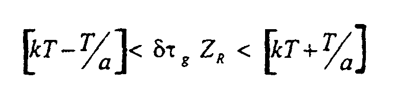
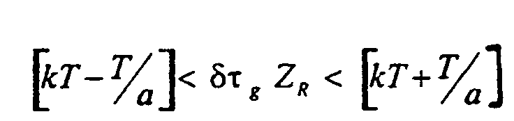
- the distance Z R between modulators will be chosen such that the difference in group time ⁇ g satisfies the condition where k is integer, a ⁇ 4, and T is the bit time (for Z R in km, dt g in ps.km -1 ).
- This constraint makes it possible to obtain an approximate synchronization between the two WDM channels having the wavelengths ⁇ 1 and ⁇ 2 .
- Better synchronization can be achieved by reducing the width of the time window (i.e., by increasing a), until the desired degree of synchronization is achieved.
- Figure 1 shows schematically an example of a Optical fiber transmission system capable of transmit and regenerate a WDM optical signal formed of solitons.
- This system comprises an optical fiber F, a optical transmitter E, at least one regeneration device RG, a plurality of line optical amplifiers G1, G2 ... Gk ..., a plurality of corrugated filters FC1, FC2 ... FCk ..., and an optical receiver R.
- the optical transmitter E comprises a plurality of optical sources capable of emitting solitons having respective frequencies ⁇ 1, ⁇ 2, ... ⁇ n and a multiplexer M for introducing said solitons onto the fiber optic F.
- the receiver comprises a demultiplexer D and a plurality of detectors optics able to receive respectively the solitons having frequencies ⁇ 1, ⁇ 2, ... ⁇ n.
- Optical amplifiers are distributed, preferably regularly, along of the line to compensate for the attenuations suffered by solitons. These optical amplifiers can, so classic, be of EDFA type (for Erbium Doped Fiber Amplify).
- the fluted filters FC1, FC2 ... FCk ... are disposed downstream of the optical amplifiers G1, G2, ...; reduce the temporal width of solitons and thereby temporal jitter.
- fluted filter is meant a filter bandpass that passes a plurality of bands narrow with different center frequencies, corresponding to the wavelengths of the different channels of the WDM system multiplexed in wavelength.
- FIG. 1 schematically illustrates a device for regeneration according to the invention.
- This regeneration device RG comprises a synchronization means 2 and a modulator 4.
- the modulator 4 is a known modulator, and used to regenerate a single-frequency soliton type signal, that is to say non-WDM.
- a modulator is described in particular in the article by Nakazawa et al. cited above. It comprises a MOD optical modulator, for example of the LiNO 3 type, for performing the synchronous modulation of solitons, which is controlled by an electronic control signal produced by a clock circuit from the on-line soliton signal.
- the clock recovering means comprises an optical coupler C3 for extracting a portion of the optical signal, a clock extraction circuit CLKX, a delay line for providing an LED delay, and a GM amplifier for providing the control power required to operate the modulator MOD in LiNO 3 .
- the modulation means may comprise devices Birefringent polarization control PC. Such devices can also be provided after the filters fluted ( Figure 1).
- a currently preferred synchronization means is shown schematically in Figure 3. It includes a Optical circulator 6 with three ports P1, P2, P3, one line optical comprising an optical fiber 8 and m filters photorefractive FPR1, FPR2, ... FPRm reflective respectively at ⁇ 1, ⁇ 2, ... ⁇ m (m ⁇ n), and an optical coupler 20 intended to transmit the solitons emitted on the n-m other channels, and which are not reflected by the filters photorefractive, to the output port of the means of synchronization.
- the optical circulator is designed for transmit a received signal on its port P1 to its port P2, and a signal received on its port P2 to its port P3.
- the ports P1 and P3 respectively form the input and output synchronization means 2.
- the Soliton signal emitted in the frequency channel ⁇ i (1 i i n n) arrives on port P1, is transmitted to port P2, goes through the fiber 8 to the FPRi filter, where it is reflected to the circulator 6, and is finally transmitted to the port P3.
- the relative position of the photoreflector filters is chosen to compensate for delays between channel signals 1 to m with respect to channel signals m + 1 to n, the latter being naturally synchronized (the modulator is placed where these channels are Synchronous). This delay can be determined in the way next.
- the integer N k1 represents the maximum number of bit times included in the delay between channel n and channel k. In fact, the quantity that matters is not the accumulated delay between two individual bits belonging to the channels n and k, but rather the relative delay between the corresponding time windows.
- Photorefractive filters are advantageously made in the form of BRAGG photo-inscribed filters directly on the fiber. They offer the benefit of a rate of high extinction and allow to define in a very specifies the delay of each channel.
- FIG. 4 Another embodiment of the synchronization means is shown in FIG. 4. It comprises a demultiplexer 22 with an input and m + 1 outputs, a set of m + 1 lines in parallel, and a multiplexer 24 with m + 1 inputs and output.
- a line 26 associated with all naturally synchronized channels has no optical delay line
- the other m lines are each associated with one of the other channels and each comprise a delay line.
- optical ⁇ i (1 ⁇ i ⁇ m) introduces an optical delay such that all the n channels are synchronized at the output of the synchronization means.
- FIG. 5 Another alternative embodiment of the synchronization means is shown in FIG. 5. It comprises a splitter 28 with an input and m + 1 outputs, a set of m + 1 lines in parallel, and a concentrator 30 with m + 1 inputs and output.
- a line 32 is associated with all the naturally synchronized channels and has a corrugated filter 34 correpondant these channels, and a set of m lines which are each associated with a channel and which each comprise a line optical delay such that all the n channels are synchronized at the output of the synchronization means.
- the filter 16i (1 ⁇ i ⁇ m) of the line i and the delay ⁇ i introduced by the delay line portion of the line i are chosen respectively to let paseer the solitons emitted on the channel i and to delay said solitons d a delay ⁇ i such that the solitons transmitted on line i are synchronous at the output of the concentrator with the solitons transmitted on line 32.
- a selective delay per channel can be obtained by using a dispersion-compensated optical fiber or an optical fiber comprising a chirped photorefractive filter (The term "chirped”, well known to those skilled in the art, derives of the Anglo-Saxon term “chirp” used to designate a medium of transmission in which the low frequencies are propagate faster than high frequencies).
- optical coupler used for recover the clock signal
- it can be placed on the transmission line, as shown in Figure 2, but that it could also be placed on the optical fiber 8 (Figure 3), or on one of the m + 1 parallel lines ( Figure 4) or ( Figure 5), or in one another point of the synchronization means.
Landscapes
- Engineering & Computer Science (AREA)
- Computer Networks & Wireless Communication (AREA)
- Signal Processing (AREA)
- Physics & Mathematics (AREA)
- Electromagnetism (AREA)
- Optical Communication System (AREA)
Description

- la figure 1 illustre schématiquement un système de transmission optique sur fibre optique selon l'invention,
- la figure 2 montre schématiquement un dispositif de régénération selon l'invention,
- la figure 3 illustre un premier mode de réalisation du moyen de synchronisation selon l'invention, conçu pour resynchroniser les solitons émis par les n canaux d'une liaison WDM à n canaux
- la figure 4 illustre un deuxième mode de réalisation du moyen de synchronisation selon l'invention, conçu pour resynchroniser les solitons émis par les n canaux d'une liaison WDM à n canaux, et
- la figure 5 illustre un troisième mode de réalisation du moyen de synchronisation selon l'invention, conçu pour resynchroniser les solitons émis par les n canaux d'une liaison WDM à n canaux.



Claims (11)
- Dispositif de régénération d'un signal optique ayant la forme d'un train de bits représentés par des solitons définis notamment par une longueur d'onde de propagation et un rythme de bits, ledit dispositif comprenant un circuit de récupération d'horloge (C3, CLKX) pour extraire un signal d'horloge dudit signal optique et un modulateur optique (MOD) pour régénérer lesdits solitons, et étant caractérisé en ce qu'il comporte en amont du modulateur un moyen de synchronisation (2) pour des solitons émis sur n (n>1) canaux ayant des longueurs d'onde respectives différentes, lesdits canaux et lesdites longueurs d'onde différentes étant associés à des temps de groupe différents, ledit moyen de synchronisation comportant m (l≤m<n) lignes à retard optiques, le retard τi (1≤i≤m) pour la ligne i étant choisi de manière à compenser les différences entre les temps de groupe associés aux différents canaux.
- Dispositif selon la revendication 1 caractérisé en ce que le moyen de synchronisation comporte m lignes à retard optiques, avec m<n, le retard τi (l≤i<m) pour le canal i étant choisi de manière à compenser les différences de temps de groupe entre m canaux, et au moins une ligne sans retard optique pour les n-m autres canaux.
- Dispositif selon la revendication 2 caractérisé en ce que le moyen de synchronisation comprend une seule ligne sans retard optique (26,;32), ladite ligne sans retard optique étant conçue pour recevoir des solitons multiplexés émis par une pluralité de canaux.
- Dispositif selon l'une des revendications 1 à 2 caractérisé en ce que le moyen de synchronisation comprend une ligne optique (8) équipée de m filtres photoréfractifs en série (FPR1, FPR2, ...FPRm), la fréquence de chaque filtre étant associée à celle d'un canal et la position respective de chaque filtre i (1≤i≤m) étant choisie de manière à produire ledit retard τi pour les solitons émis sur le canal i; un moyen de contrôle (6) pour émettre vers ladite ligne optique les solitons reçus par le moyen de synchronisation et vers un port de sortie du moyen de synchronisation les solitons réfléchis par les filtres de ladite ligne optique; et un coupleur optique (20) pour transmettre les solitons émis sur les n-m canaux qui ne sont pas associés à un filtre vers le port de sortie du moyen de synchronisation.
- Dispositif selon la revendication 4 caractérisé en ce que ledit moyen de contrôle (6) est un circulateur optique à trois ports.
- Dispositif selon l'une des revendications 1 ou 2, caractérisé en ce que le moyen de synchronisation comprend un démultiplexeur (22), un ensemble de m lignes en parallèle comportant chacune un tronçon de ligne à retard optique, un multiplexeur (24), et au moins une ligne sans retard optique (26) disposée entre le démultiplexeur et le multiplexeur.
- Dispositif selon l'une des revendications 1 ou 2 caractérisé en ce que le moyen de synchronisation comprend un diviseur (28); un ensemble de m lignes en parallèle comportant chacune un filtre (161, ...16m) pour sélectionner un canal et un tronçon de ligne à retard optique; un concentrateur (30); et au moins une ligne sans retard optique (32) entre le diviseur (28) et le concentrateur (30), ladite ligne sans retard comprenant un filtre (34) pour sélectionner au moins un canal.
- Dispositif selon l'une des revendications 1 à 7 caractérisé en ce qu'il comprend un filtre cannelé (Fck) en sortie du modulateur synchrone (MOD).
- Système de transmission optique de signaux ayant chacun la forme d'un train de bits représentés par des solitons, qui sont définis notamment par une longueur d'onde de propagation et un rythme de bits, ledit système de transmission comprenant au moins un émetteur (E) et un récepteur (R) reliés par une fibre optique (F), ledit système étant caractérisé en ce qu'il comprend au moins un dispositif de régénération optique selon l'une des revendications 1 à 8.
- Système selon la revendication 9 caractérisé en ce que chaque dispositif de régénération est disposé à une distance ZR, après ledit émetteur ou le dispositif de régénération qui le précède, choisie telle que son produit avec la différence de temps d'arrivée δτg = τg(λ1) - τg(λℓ) satisfasse la conditionoù k est entier, a≥4, T est le temps bit (pour ZR en km, dtg en ps.km-1), et λ1 et λℓ sont les extrémités de la bande spectrale définie par ledit sous-ensemble de n-m canaux.
- Système selon la revendication 10 caractérisé par un circuit de récupération d'horloge qui extrait du signal optique un signal de longueur d'onde λk comprise entre les longueurs d'onde λ1 et λℓ ; tel que τg(λk).ZR = kT.
Applications Claiming Priority (3)
| Application Number | Priority Date | Filing Date | Title |
|---|---|---|---|
| FR9701476A FR2759516B1 (fr) | 1997-02-10 | 1997-02-10 | Procede et dispositif de regeneration en ligne d'un signal transmis par solitons multiplexes en longueur d'onde et systeme de telecommunications optiques comprenant un tel dispositif de regeneration |
| FR9701476 | 1997-02-10 | ||
| PCT/FR1998/000258 WO1998035459A1 (fr) | 1997-02-10 | 1998-02-10 | Procede et dispositif de regeneration en ligne d'un signal transmis par solitons multiplexes en longueur d'onde et systeme de telecommunications optiques comprenant un tel dispositif de regeneration |
Publications (2)
| Publication Number | Publication Date |
|---|---|
| EP0897624A1 EP0897624A1 (fr) | 1999-02-24 |
| EP0897624B1 true EP0897624B1 (fr) | 2005-09-28 |
Family
ID=9503497
Family Applications (1)
| Application Number | Title | Priority Date | Filing Date |
|---|---|---|---|
| EP98908164A Expired - Lifetime EP0897624B1 (fr) | 1997-02-10 | 1998-02-10 | Procede et dispositif de regeneration en ligne d'un signal transmis par solitons multiplexes en longueur d'onde et systeme de telecommunications optiques comprenant un tel dispositif de regeneration |
Country Status (6)
| Country | Link |
|---|---|
| US (1) | US6373608B1 (fr) |
| EP (1) | EP0897624B1 (fr) |
| JP (1) | JP2000511654A (fr) |
| DE (1) | DE69831709T2 (fr) |
| FR (1) | FR2759516B1 (fr) |
| WO (1) | WO1998035459A1 (fr) |
Families Citing this family (21)
| Publication number | Priority date | Publication date | Assignee | Title |
|---|---|---|---|---|
| AUPP208398A0 (en) * | 1998-03-02 | 1998-03-26 | University Of Melbourne, The | An optical device for dispersion compensation |
| AU761010B2 (en) * | 1998-03-02 | 2003-05-29 | University Of Melbourne, The | An optical device for dispersion compensation |
| FR2787659B1 (fr) * | 1998-12-21 | 2006-07-21 | Cit Alcatel | Procede de reduction des distorsions d'intensite induites par la modulation de phase croisee dans un systeme de transmission a fibre optique a multiplexage de longueur d'onde et unite pour la mise en oeuvre du procede |
| FR2790160B1 (fr) | 1999-02-19 | 2001-05-04 | Cit Alcatel | Systeme de transmission regenere wdm |
| JP3707955B2 (ja) * | 1999-05-10 | 2005-10-19 | 平河ヒューテック株式会社 | Wdm光伝送システム |
| JP3732371B2 (ja) * | 1999-09-09 | 2006-01-05 | 沖電気工業株式会社 | 光信号発生回路 |
| US6612743B1 (en) * | 1999-09-09 | 2003-09-02 | California Institute Of Technology | Wavelength division multiplexed optical solitons |
| FR2799070B1 (fr) * | 1999-09-23 | 2002-02-08 | Cit Alcatel | Regenerateur de signaux optiques multiplexes en longueur d'onde |
| FR2799011B1 (fr) * | 1999-09-24 | 2001-12-14 | Cit Alcatel | Regenerateur optique pour signaux rz limitant le bruit dans les "zeros" |
| US6795653B1 (en) * | 1999-12-13 | 2004-09-21 | Nortel Networks Limited | Apparatus for reshaping optical pulses |
| US6570694B1 (en) * | 2000-03-03 | 2003-05-27 | Alcatel | System and method for low-jitter asynchronous optical regeneration using wavelength sampling |
| US7203429B2 (en) * | 2001-05-07 | 2007-04-10 | Tyco Telecommunications (Us) Inc. | Optical transmission system using optical signal processing in terminals for improved system performance |
| FR2832571B1 (fr) * | 2001-11-22 | 2004-04-16 | Cit Alcatel | Systeme de transmission par fibres optiques a horloge commune |
| JP3782407B2 (ja) * | 2002-08-06 | 2006-06-07 | ズン−クック,チェ | 波長分割多重方式手動型光加入者網システム(wavelengthdivisionmultiplexing−passiveopticalnetwork) |
| ATE301843T1 (de) * | 2003-06-16 | 2005-08-15 | Cit Alcatel | Elektro-optischer absorptionsmodulator mit begrenzer für das steuersignal |
| US7302728B2 (en) * | 2004-03-11 | 2007-12-04 | Coe Kunz | Cleaning implement for golfers |
| JP4342393B2 (ja) * | 2004-07-14 | 2009-10-14 | 株式会社東芝 | 携帯端末機器に装着される電子装置及び電子装置の制御方法 |
| US7945165B2 (en) * | 2007-11-16 | 2011-05-17 | Alcatel-Lucent Usa Inc. | Optical signal synchronizer |
| US8073333B2 (en) * | 2007-11-16 | 2011-12-06 | Alcatel Lucent | Multiplex delay unit |
| US8260142B2 (en) * | 2009-06-29 | 2012-09-04 | Alcatel Lucent | Multi-channel optical arrayed time buffer |
| CN106034003B (zh) * | 2015-03-10 | 2019-05-17 | 四川泰富地面北斗科技股份有限公司 | 基于双纤传递超精密时间频率信号的方法 |
Family Cites Families (6)
| Publication number | Priority date | Publication date | Assignee | Title |
|---|---|---|---|---|
| US5502588A (en) * | 1992-06-24 | 1996-03-26 | France Telecom | Optical transmission process and system for sending solitons over very long distances |
| US5357364A (en) * | 1992-06-25 | 1994-10-18 | At&T Bell Laboratories | Soliton transmission system having sliding-frequency guiding filters |
| JPH08286218A (ja) * | 1995-04-17 | 1996-11-01 | Nippon Telegr & Teleph Corp <Ntt> | 波長多重光ソリトン中継伝送装置 |
| FR2743964B1 (fr) * | 1996-01-23 | 1998-03-13 | Alcatel Submarcom | Methode et dispositif de regeneration en ligne d'un signal transmis par solitons multiplexes en longueur d'onde via la modulation synchrone et systeme de telecommunications optiques utilisant la methode |
| JP3522044B2 (ja) * | 1996-04-19 | 2004-04-26 | 富士通株式会社 | 光伝送システム |
| US5852687A (en) * | 1997-07-09 | 1998-12-22 | Trw Inc. | Integrated optical time delay unit |
-
1997
- 1997-02-10 FR FR9701476A patent/FR2759516B1/fr not_active Expired - Fee Related
-
1998
- 1998-02-10 JP JP10533900A patent/JP2000511654A/ja active Pending
- 1998-02-10 US US09/155,901 patent/US6373608B1/en not_active Expired - Lifetime
- 1998-02-10 DE DE69831709T patent/DE69831709T2/de not_active Expired - Lifetime
- 1998-02-10 EP EP98908164A patent/EP0897624B1/fr not_active Expired - Lifetime
- 1998-02-10 WO PCT/FR1998/000258 patent/WO1998035459A1/fr not_active Ceased
Also Published As
| Publication number | Publication date |
|---|---|
| JP2000511654A (ja) | 2000-09-05 |
| DE69831709D1 (de) | 2005-11-03 |
| WO1998035459A1 (fr) | 1998-08-13 |
| FR2759516A1 (fr) | 1998-08-14 |
| EP0897624A1 (fr) | 1999-02-24 |
| FR2759516B1 (fr) | 1999-03-26 |
| US6373608B1 (en) | 2002-04-16 |
| DE69831709T2 (de) | 2006-06-29 |
Similar Documents
| Publication | Publication Date | Title |
|---|---|---|
| EP0897624B1 (fr) | Procede et dispositif de regeneration en ligne d'un signal transmis par solitons multiplexes en longueur d'onde et systeme de telecommunications optiques comprenant un tel dispositif de regeneration | |
| EP0786877B1 (fr) | Méthode et dispositif de régénération en ligne d'un signal transmis par solitons multiplexés en longueur d'onde via la modulation synchrone et système de télécommunications optiques utilisant la méthode | |
| FR2737630A1 (fr) | Systeme de transmission optique a multiplexage de longueurs d'onde et dispositif d'emission utilise dans ce systeme de transmission | |
| EP1969748B1 (fr) | Transmission optique entre un terminal central et une pluralite de terminaux clients via un reseau optique | |
| FR2715524A1 (fr) | Système de communication de type soliton optique ainsi qu'émetteur et récepteur optiques pour ce système. | |
| EP0862286B1 (fr) | Régénération optique pour des systèmes de transmission à fibre optique à signaux non solitons | |
| FR2724510A1 (fr) | Systeme de transmission optique | |
| EP0763912B1 (fr) | Doubleur tout optique et régénérateur de solitons utilisant le doubleur | |
| EP1014607B1 (fr) | Procédé de réduction des distorsions d'intensité induités par la modulation de phase croisée dans un systeme de transmission à fibre optique à multiplexage de longueur d'onde | |
| JPH11239099A (ja) | 同期偏波スクランブラを用いた光通信システム及び光受信装置 | |
| EP1087553A1 (fr) | Régénérateur de signaux optiques multiplexés en longueurs d'onde | |
| EP0984572B1 (fr) | Dispositif de compensation de la dispersion de polarisation des canaux dans un signal a multiplexage en longueur d'onde | |
| EP1030471B1 (fr) | Système de transmission optique régénéré WDM | |
| EP1315320A2 (fr) | Système de transmission par fibres optiques à horloge commune | |
| EP0975106B1 (fr) | Dispositif de régénération en ligne d'un signal optique de solitons par une modulation synchrone de ces solitons et système de transmission comportant un tel dispositif | |
| EP0961425A1 (fr) | Système de transmission à fibre optique à signaux solitons et à double filtrage | |
| EP0859482B1 (fr) | Régénération optique pour des systèmes de transmission à fibre optique à signaux solitons et à multiplexage de longueur d'onde | |
| EP0910185B1 (fr) | Système de transmission à fibre optique à signaux solitons et à multiplexage de longueur d'onde | |
| EP0910186B1 (fr) | Réparation de systèmes sous-marins de transmision à fibre optique à signaux solitons et à multiplexage de longueur d'onde | |
| EP0924883A1 (fr) | Reduction de la gigue de collission par echange de longueurs d'onde dans un système de transmission à fibre optique à signaux solitons et à multiplexage de longueurs d'onde | |
| Marco et al. | Device and method for compensating polarization mode dispersion in an optical communication system | |
| FR2803399A1 (fr) | Dispositif de generation de porteuses pour systeme de transmission optique a multiplexage en longueur d'onde a signaux rz | |
| EP1021004A1 (fr) | Procédé et dispositif pour la stabilisation de solitons optiques |
Legal Events
| Date | Code | Title | Description |
|---|---|---|---|
| PUAI | Public reference made under article 153(3) epc to a published international application that has entered the european phase |
Free format text: ORIGINAL CODE: 0009012 |
|
| AK | Designated contracting states |
Kind code of ref document: A1 Designated state(s): DE GB IT SE |
|
| RAP3 | Party data changed (applicant data changed or rights of an application transferred) |
Owner name: ALCATEL |
|
| 17P | Request for examination filed |
Effective date: 19990215 |
|
| 17Q | First examination report despatched |
Effective date: 20031212 |
|
| GRAP | Despatch of communication of intention to grant a patent |
Free format text: ORIGINAL CODE: EPIDOSNIGR1 |
|
| GRAS | Grant fee paid |
Free format text: ORIGINAL CODE: EPIDOSNIGR3 |
|
| GRAA | (expected) grant |
Free format text: ORIGINAL CODE: 0009210 |
|
| AK | Designated contracting states |
Kind code of ref document: B1 Designated state(s): DE GB IT SE |
|
| REG | Reference to a national code |
Ref country code: GB Ref legal event code: FG4D Free format text: NOT ENGLISH |
|
| REF | Corresponds to: |
Ref document number: 69831709 Country of ref document: DE Date of ref document: 20051103 Kind code of ref document: P |
|
| GBT | Gb: translation of ep patent filed (gb section 77(6)(a)/1977) |
Effective date: 20051101 |
|
| PG25 | Lapsed in a contracting state [announced via postgrant information from national office to epo] |
Ref country code: SE Free format text: LAPSE BECAUSE OF FAILURE TO SUBMIT A TRANSLATION OF THE DESCRIPTION OR TO PAY THE FEE WITHIN THE PRESCRIBED TIME-LIMIT Effective date: 20051228 |
|
| PGFP | Annual fee paid to national office [announced via postgrant information from national office to epo] |
Ref country code: IT Payment date: 20060228 Year of fee payment: 9 |
|
| PLBE | No opposition filed within time limit |
Free format text: ORIGINAL CODE: 0009261 |
|
| STAA | Information on the status of an ep patent application or granted ep patent |
Free format text: STATUS: NO OPPOSITION FILED WITHIN TIME LIMIT |
|
| 26N | No opposition filed |
Effective date: 20060629 |
|
| PG25 | Lapsed in a contracting state [announced via postgrant information from national office to epo] |
Ref country code: IT Free format text: LAPSE BECAUSE OF NON-PAYMENT OF DUE FEES Effective date: 20070210 |
|
| PGFP | Annual fee paid to national office [announced via postgrant information from national office to epo] |
Ref country code: DE Payment date: 20160218 Year of fee payment: 19 |
|
| PGFP | Annual fee paid to national office [announced via postgrant information from national office to epo] |
Ref country code: GB Payment date: 20160217 Year of fee payment: 19 |
|
| REG | Reference to a national code |
Ref country code: DE Ref legal event code: R119 Ref document number: 69831709 Country of ref document: DE |
|
| GBPC | Gb: european patent ceased through non-payment of renewal fee |
Effective date: 20170210 |
|
| PG25 | Lapsed in a contracting state [announced via postgrant information from national office to epo] |
Ref country code: DE Free format text: LAPSE BECAUSE OF NON-PAYMENT OF DUE FEES Effective date: 20170901 |
|
| PG25 | Lapsed in a contracting state [announced via postgrant information from national office to epo] |
Ref country code: GB Free format text: LAPSE BECAUSE OF NON-PAYMENT OF DUE FEES Effective date: 20170210 |