EP1031300A1 - Kopfstütze und ihr herstellungsverfahren - Google Patents
Kopfstütze und ihr herstellungsverfahren Download PDFInfo
- Publication number
- EP1031300A1 EP1031300A1 EP99923918A EP99923918A EP1031300A1 EP 1031300 A1 EP1031300 A1 EP 1031300A1 EP 99923918 A EP99923918 A EP 99923918A EP 99923918 A EP99923918 A EP 99923918A EP 1031300 A1 EP1031300 A1 EP 1031300A1
- Authority
- EP
- European Patent Office
- Prior art keywords
- inner cover
- opening
- edge
- box part
- slot
- Prior art date
- Legal status (The legal status is an assumption and is not a legal conclusion. Google has not performed a legal analysis and makes no representation as to the accuracy of the status listed.)
- Granted
Links
- 238000004519 manufacturing process Methods 0.000 title claims description 5
- 238000005187 foaming Methods 0.000 claims abstract description 5
- 239000000463 material Substances 0.000 claims description 142
- 239000007788 liquid Substances 0.000 claims description 47
- 239000012530 fluid Substances 0.000 claims description 18
- 238000000034 method Methods 0.000 claims description 8
- 235000014666 liquid concentrate Nutrition 0.000 abstract 1
- JOYRKODLDBILNP-UHFFFAOYSA-N Ethyl urethane Chemical compound CCOC(N)=O JOYRKODLDBILNP-UHFFFAOYSA-N 0.000 description 2
- 238000000465 moulding Methods 0.000 description 1
- 238000004826 seaming Methods 0.000 description 1
Images


Classifications
-
- B—PERFORMING OPERATIONS; TRANSPORTING
- B60—VEHICLES IN GENERAL
- B60R—VEHICLES, VEHICLE FITTINGS, OR VEHICLE PARTS, NOT OTHERWISE PROVIDED FOR
- B60R21/00—Arrangements or fittings on vehicles for protecting or preventing injuries to occupants or pedestrians in case of accidents or other traffic risks
- B60R21/02—Occupant safety arrangements or fittings, e.g. crash pads
- B60R21/055—Padded or energy-absorbing fittings, e.g. seat belt anchors
-
- B—PERFORMING OPERATIONS; TRANSPORTING
- B60—VEHICLES IN GENERAL
- B60N—SEATS SPECIALLY ADAPTED FOR VEHICLES; VEHICLE PASSENGER ACCOMMODATION NOT OTHERWISE PROVIDED FOR
- B60N2/00—Seats specially adapted for vehicles; Arrangement or mounting of seats in vehicles
- B60N2/58—Seat coverings
- B60N2/5816—Seat coverings attachments thereof
- B60N2/5841—Seat coverings attachments thereof by clamping means
-
- B—PERFORMING OPERATIONS; TRANSPORTING
- B60—VEHICLES IN GENERAL
- B60N—SEATS SPECIALLY ADAPTED FOR VEHICLES; VEHICLE PASSENGER ACCOMMODATION NOT OTHERWISE PROVIDED FOR
- B60N2/00—Seats specially adapted for vehicles; Arrangement or mounting of seats in vehicles
- B60N2/80—Head-rests
- B60N2/806—Head-rests movable or adjustable
- B60N2/809—Head-rests movable or adjustable vertically slidable
- B60N2/812—Head-rests movable or adjustable vertically slidable characterised by their locking devices
- B60N2/818—Head-rests movable or adjustable vertically slidable characterised by their locking devices with stepwise positioning
-
- B—PERFORMING OPERATIONS; TRANSPORTING
- B60—VEHICLES IN GENERAL
- B60N—SEATS SPECIALLY ADAPTED FOR VEHICLES; VEHICLE PASSENGER ACCOMMODATION NOT OTHERWISE PROVIDED FOR
- B60N2/00—Seats specially adapted for vehicles; Arrangement or mounting of seats in vehicles
- B60N2/80—Head-rests
- B60N2/806—Head-rests movable or adjustable
- B60N2/838—Tiltable
- B60N2/841—Tiltable characterised by their locking devices
- B60N2/85—Tiltable characterised by their locking devices with continuous positioning
Definitions
- the present invention relates to a headrest and a method for manufacturing the headrest that attached to a seat used as an automobile seat, a business seat, a consultation seat or a seat for house use.
- the present invention relates to a headrest that has a head angle adjusting mechanism and is manufactured by foaming and molding an expandable material together with a surface material and a method for manufacturing such a headrest.
- a headrest of the art comprises of a metallic or plastic stay frame as a skeleton of the headrest, a box like shaped surface material and a foamed cushion pad molded together with the surface material.
- the surface material is seamed into a desirable box like shape, and a top part of the stay frame is capped with the surface material.
- a liquid expandable material such as urethane is injected inside the box like shaped surface material and is foamed and molded together with the surface material.
- the surface material is manufactured by seaming several sheet materials into a box like shape corresponding to an outline of the headrest. Its margin to seam is necessary to hide inside the box like shaped surface material to make an appearance of the surface material better.
- the seat materials are firstly seamed so as to appear the inner side of the box like shaped surface material and provide an opening in a part corresponding to a bottom of the headrest. Then, the inner side of the surface material is disappeared by passing the surface material through the opening so as to appear its outer side.
- the top part of the stay frame is inserted in the surface material through this opening.
- the stay frame comprises of the U-shaped top part and a pair of leg parts extending downward from both ends of this top part.
- the foamed cushion pad is molded together with the surface material as follows.
- the top part of the stay frame is inserted in the box like surface material.
- a liquid expandable material is injected in the surface material and is foamed.
- the means comprise of an upper and lower plates having an opening for a liquid expandable material injecting nozzle and two holes for passing the leg parts of the stay frame, respectively.
- the leg parts of the stay frame pass through the holes of those plates so as to place those plates at a predetermined position corresponding to the bottom of the headrest.
- One plate is disposed in parallel to another plate, and a gap is provided between those plates.
- the upper plate has a window as a fluid passage communicated with the gap between those plates.
- the opening of the surface material is inserted and freely held in the gap between those plates, and the upper plate having the fluid passage is disposed inside the surface material.
- the liquid expandable material injecting nozzle is inserted in the inner space of the surface material through the openings coaxially provided in both plates and the liquid expandable material is injected and foamed therein.
- the liquid expandable material injected passes through the fluid passage of the upper plate and is introduced between the upper plate and a circumferential portion of the opening of the surface material. This liquid expandable material is foamed and cured, and thereby, the opening of the surface material is completely closed.
- a vehicle having a variety of functions has been developed. For example, in order to contain more passages or the like in a vehicle, a seat back is used as a part of a bed such that a rear seat is collapsed forward to create a more space for containing more passages.
- a rear seat In such a vehicle, a rear seat must be tilted forward completely to make a more space.
- the rear seat touches on a seat back of a front seat when the rear seat is tilting.
- the rear seat cannot be tilted completely so that an enough space cannot be created.
- the headrest is detached from the rear seat, the rear seat can be tilted completely.
- an additional space for putting the detached headrest will be required.
- the head angle adjusting mechanism is attached to the top part of the stay frame and, as well as a headrest of the art described above, the top part of the stay frame is capped with a surface material.
- a foamed cushion pad is formed so as to introduce into structural components of the head angle adjusting mechanism, and as a result, this pad hampers the functions of the head angle adjusting mechanism.
- an object of the present invention is to provide a novel headrest and a headrest manufacturing method in which a foamed cushion pad is molded together with a surface material so as not to introduce a liquid expandable material into structural components of a head angle adjusting mechanism and it can be done to take the headrest to pieces without taking much time and costing much labor in order to recycle its components.
- a headrest according to the present invention comprises of:
- the head frame is covered with the inner cover such that the leg part of the base frame passes through the slot and extends outside the box part.
- the head angle adjusting mechanism of the stay frame is also covered with the box part so as to rotate the head frame backward and forward together with the inner cover.
- Such a headrest can be manufactured as follows.
- a headrest of the present invention comprises of: a stay frame assembly 10 as a skeleton of the headrest; an inner cover 30 comprising of a box part 31 and a plate part 32 connected to a bottom 36 of the box part 31 so as to remain a gap 35 between the bottom 36 of the box part 31 and the plate part 32; and a foamed cushion pad 60 molded together with a surface material 70 so as to cover around the box part 31 and enter in the gap 35 between the bottom 36 of the box part 31 and the plate part 32.
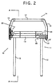
- the stay frame assembly 10 comprises of: a U-shaped base frame 11 having a pair of leg parts 12 extending downward; and a U-shaped head frame 14 connected to a top part of the base frame 11 so as to freely tilt backward and forward with respect to the base frame 11.
- the top part of the base frame 11 is bended forward so as to take a right angle to the leg parts 12 (see Fig.3), and an axial rod 13 extending crosswise is rigidly connected to the bended top part of the base frame 11 so as to position below this bended part.
- a pair of leg parts 12 is formed in a lower part of the base frame 11 so as to extend downward. Those leg parts 12 are inserted in openings (not shown) provided in a top part of a seat back, and thus, the headrest can be attached to the seat.
- the head frame 14 comprises of a pair of triangular side plates 15, 16 (the left side plate 15 is shown in Fig.3) and a connecting rod 17.
- the upper parts of those side plates 15, 16 are rigidly connected to both end parts of this connecting rod 17, respectively, so as to face each other, and thus, the head frame 14 has a U-shaped form.
- the lower parts of the left and right side plates 15, 16 are connected to the axial rod 13 rigidly connected to the base frame 11, respectively, so as to freely rotate backward and forward with respect to this axial rod 13.
- a head angle adjusting mechanism 20 is incorporated in the stay frame assembly 10.
- a conventional type head angle adjusting mechanism broadly used for adjusting a tilting angle of a seat back can be used.
- a spring 21 is disposed such that one end of the spring 21 is hooked on a pin 22 rigidly connected to the axial rod 13 and another end of the spring 21 is placed and pressed on a flange 16' of the right side plate 16, so that a rotational force is always acted to the head frame 14 so as to rotate the head frame 14 backward (i.e. a direction shown by an allow R in Fig.3).
- the hook portion 28 of the stopper 26 is disengaged from the groove 24 and the stopper 26 rotates together with the left side plate 15 forward with respect to the axial rod 13.
- the stopper 26 moves along the rim of the cam 23 and then engages into the groove 25.
- the head angle of the head frame 14 with respect to the base frame 11 depends on each position of the groove provided on the rim of the cam 23.
- the head angle adjusting mechanism 20 has an additional mechanism (not shown) for disengaging the hook portion 28 of the stopper 26 from the groove 25 when the head frame 14 is further tilted forward and then returning the stopper 26 to its original position together with the left side plate 15 by the rotational force acted on the left side plate 15 that is generated by the spring 21 so as to engage the hook portion 26 into the groove 24.
- the inner cover 30 comprises of a box part 31 and the plate part 32 rigidly connected to the bottom 36 of the box part 31 so as to remain the gap 36 between the bottom 36 and the plate part 32.
- the plate part 32 has slots 33 communicated with an inner space of the box part 31 and is connected by walls 33' that form the slots 33.
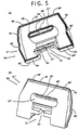
- the inner cover is composed of two portions such as a front portion (a first portion) and a rear portion (a second portion), as shown in Figs.4 and 5.
- the front portion 40 comprises of: a front side part 31' of the box part 31 of the inner cover 30; and the plate part 32 rigidly connected to a bottom 36' of the front side part 31' so as to have the gap 35 between the bottom 36' and the plate part 32 as described above.
- the rear part 50 comprises of a rear side part 31'' of the box part 31, and when the front side part 50 is attached to the rear side part 50, the inner space of the box part 31 is formed so as to cover liquid-tightly the head angle adjusting mechanism 20 and the head frame of the stay frame assembly 10.
- the front side part 50 can be attached to the rear side part 50 by fitting a tongue formed on an edge of one part with a slot formed on an edge of another part and then latching those parts, and thereby, both parts can be liquid-tightly connected each other.
- the tongue 53 is provided along the edge of the left and right sides and the top side of the rear part 50
- the slot 44 is provided along the edge of the left and right sides and the top side of the front part 40
- the front and rear parts 40, 50 are liquid-tightly connected each other by fitting the tongue 53 of the rear part 50 with the slot 44 of the front part 40 and then latching those parts 40, 50 by latches 46, 46' provided on their left and right sides and their top sides, and thereby, the box part 31 of the inner cover 30 is formed.
- a U-shaped wall 43 is provided over the left and right sides and the front side so as to form a half-annular socket cavity.
- a hollow 51 corresponding to a size of the central rear part 41 of the bottom 36' of the front part 40, and a flange 55 is provided horizontally along a lower end of this hollow 51.
- This flange 55 is slid and inserted in the socket cavity and, at the same time, both rims in both sides of the bottom 36' of the central rear part 41 of the front portion 40 is inserted in the slot 54 provided along the circumference of both sides of the bottom 36'' of the hollow 51 of the rear portion 50, and then those portions are latched by use of latches 47, 47', and thereby, the bottom 36' of the front portion 40 and the bottom 36'' of the rear portion 50 are liquid-tightly connected, and thus, the bottom 36 of the box part 31 of the inner cover 30 is formed.
- an ellipse like opening 37' extending left and right is provided on a central part of the front portion 40, and a slot 45 is formed along the end of this opening 37'.
- an ellipse like opening 37'' extending left and right is provided on a central part of the rear portion 50, and a tongue 56 is provided along the end of this opening 37''.
- the tongue 56 of the rear portion 50 is inserted in the slot 45 of this opening 37', and both portions are latched by use of latches 46, 46', and thereby, both openings 37', 37'' are liquid-tightly connected each other, and thus, the opening 37 (see Fig.
- a pair of slots 33 are provided in the plate part 40 so as to communicate with the inside of the front portion 40.
- the leg parts 12 of the base frame 11 are extending outside the front portion 40 through those slots 33, and the front sides of the head frame 14 and the head angle adjusting mechanism 20 are placed on the inside of this front portion 40.
- the rear portion 50 is, as described above, connected liquid-tightly to the front portion 40, and thereby, the head frame and the head angle adjusting mechanism are liquid-tightly contained inside the box part 31 of the inner cover 30.
- each slot 33 formed in the plate part 32 is an ellipse like shape extending backward and forward so as to tilt the head frame 14 backward and forward together with the front portion 40 with respect to the base frame 11.
- a plurality of windows 42 as a fluid passage communicated with the gap 35 between the bottom 36 of the inner cover 30 and the plate part 32 are provided in the central rear part 41 exposed outside the inner cover 30.
- a liquid expandable material injecting nozzle inlet 34 is provided in the central rear part 41 so as to pass through both of the plate part 32 and the central rear part 41.
- a liquid expandable material injecting nozzle guide channel 52 is vertically formed above the hollow 51 of the rear portion 50 so as to position below the opening 37'' and on an axis of the liquid expandable material injecting nozzle inlet 34formed in the central rear part 41 of the front portion 40.
- the windows 42 as the fluid passage formed in the central rear part 41 of the front portion 40 are formed by a plurality of ribs extending parallel to the plate part 32.
- a plurality of ribs are provided on a lower part of the front side 31' of the front portion 40, as well as the central rear part 41.
- the surface material 70 is seamed in a box like shape corresponding to an outline of the headrest.
- the surface material 70 has an inner space and an opening (not shown) extending left and right, and this opening communicates with the inner space of the surface material 70 and is provided in a part corresponding to the bottom of the headrest As described below, a circumferential part of the opening is inserted and held in the gap 35 between the box part 31 and the plate part 32. That is, the circumferential part of the opening of the surface material 70 is freely held in the gap 35 so that this circumferential part allows an expansion of the whole of the surface material 70 without locally acting a tension to this circumferential part when a liquid expandable material is foamed between the box part 31 and the surface material 70.
- a headrest of the present invention is manufactured as follows.
- the head frame 14 and the head angle adjusting mechanism 20 of the stay frame assembly 10 is contained in the inner cover 30.
- the box part 31 of the inner cover 30 is contained in the surface material 70 through the opening of the surface material 70, and the circumferential part of the opening of the surface material 70 is freely held in the gap 35 between the bottom 36 of the box part 31 and the plate part 32 of the inner cover 30.
- a liquid expandable material injecting nozzle (not shown) is inserted between the box part 31 and the surface material 70 through the inlet 34 formed in the plate part 32 of the inner cover 30, and a tip of the nozzle is positioned just below the opening 37 of the box part 31 through the nozzle guide channel 52 formed in the rear portion 50.
- a well-known expandable material such as urethane is injected from the rear side of the inner cover 30 and is injected between the surface material 70 and the box 31.
- the liquid expandable material injected is flown upward along the surface of the rear portion 50.
- the liquid expandable material is also flown through the opening 37 of the box part 31 and is then flown along the surface of the front portion 40.
- the liquid expandable material flown downward along the surface of the rear portion 50 passes through a plurality of windows 42 as a fluid passage and introduces between the bottom 36 of the box part 31 and the circumferential part of the opening of the surface material 70 freely held in the gap 35.
- the liquid expandable material flown downward along the surface of the front portion 40 introduces between the the bottom 36 of the box part 31 and the circumferential part of the opening of the surface material 70 freely held in the gap 35 through a plurality of ribs formed on the lower part of the front portion 40.
- the head frame 14 and the head angle adjusting mechanism 20 are liquid-tightly contained inside the inner cover 30 as described above, and thus, the liquid expandable material injected is not introduced inside the inner cover 30.
- the liquid expandable material is foamed between the surface material 70 and the box part 31 of the inner cover 30.
- a foamed body that is, a foamed cushion pad 60
- the liquid expandable material introduced between the bottom 36 of the box part 31 and the circumferential part of the opening of the surface material 70 freely held in the gap 35 is foamed so as to press the circumferential part of the opening of the surface material 70 onto the plate part 32 so that the opening of the surface material 70 is completely closed at the gap 35 and the surface material 70 is strongly held in the gap 35.
- the nozzle is taken out through the inlet 34 and the inlet 34 is then capped with a cap 80 (Fig.1).
- the headrest as shown in Fig.1 is manufactured as described above.
- the present invention has several effects as described below.
- the head frame is covered with the inner cover so as to pass the leg part of the base frame through the slot of the inner cover and extend the leg part outside the inner cover and the head angle adjusting mechanism is also covered with the inner cover so as to tilt the head frame backward and forward together with the inner cover.
- the foamed cushion pad cannot be introduced inside the inner cover and does not hamper the functions of the head angle adjusting mechanism.
- the head frame and the head angle adjusting mechanism are contained in the inner cover and the inner cover is covered with the foamed body.
- the circumferential part of the opening of the surface material is inserted in the gap between the box part and the plate part of the inner covet
- the opening of the surface material is closed by the plate part of the inner cover so that the circumferential part of the opening of the surface material can be held tightly.
Landscapes
- Engineering & Computer Science (AREA)
- Mechanical Engineering (AREA)
- Aviation & Aerospace Engineering (AREA)
- Transportation (AREA)
- Chair Legs, Seat Parts, And Backrests (AREA)
- Seats For Vehicles (AREA)
Applications Claiming Priority (3)
| Application Number | Priority Date | Filing Date | Title |
|---|---|---|---|
| JP10258152A JP2951953B1 (ja) | 1998-09-11 | 1998-09-11 | ヘッドレスト及びその製造方法 |
| JP25815298 | 1998-09-11 | ||
| PCT/JP1999/003007 WO2000015082A1 (en) | 1998-09-11 | 1999-06-04 | Head rest and method of manufacturing head rest |
Publications (3)
| Publication Number | Publication Date |
|---|---|
| EP1031300A1 true EP1031300A1 (de) | 2000-08-30 |
| EP1031300A4 EP1031300A4 (de) | 2001-01-24 |
| EP1031300B1 EP1031300B1 (de) | 2003-08-20 |
Family
ID=17316256
Family Applications (1)
| Application Number | Title | Priority Date | Filing Date |
|---|---|---|---|
| EP99923918A Expired - Lifetime EP1031300B1 (de) | 1998-09-11 | 1999-06-04 | Kopfstütze und ihr herstellungsverfahren |
Country Status (7)
| Country | Link |
|---|---|
| US (1) | US6499805B1 (de) |
| EP (1) | EP1031300B1 (de) |
| JP (1) | JP2951953B1 (de) |
| KR (1) | KR20010020566A (de) |
| CA (1) | CA2310580A1 (de) |
| DE (1) | DE69910536T2 (de) |
| WO (1) | WO2000015082A1 (de) |
Cited By (1)
| Publication number | Priority date | Publication date | Assignee | Title |
|---|---|---|---|---|
| ES2192116A1 (es) * | 2000-12-26 | 2003-09-16 | Lear Corp Spain S L | Sistema de centraje y fijacion de una tela para espumado de apoyacabezas de asiento de automovil. |
Families Citing this family (35)
| Publication number | Priority date | Publication date | Assignee | Title |
|---|---|---|---|---|
| US20050072433A1 (en) * | 2001-10-22 | 2005-04-07 | Intier Automotive | Open style head restraint with closeout and method for making same |
| DE10161587A1 (de) * | 2001-12-14 | 2003-06-26 | Dauphin Friedrich W Gmbh | Stuhl |
| US7575282B2 (en) * | 2004-03-10 | 2009-08-18 | Gill Industries, Inc. | Foldable head restraint |
| US6935696B2 (en) * | 2003-08-04 | 2005-08-30 | Gill Industries, Inc. | Head restraint mechanism and method of making same |
| US7341312B2 (en) * | 2003-08-04 | 2008-03-11 | Gill Industries, Inc. | Foldable head restraint |
| US6899395B2 (en) * | 2003-10-28 | 2005-05-31 | Lear Corporation | Cam-driven four-way head restraint assembly |
| US20050127734A1 (en) * | 2003-12-16 | 2005-06-16 | Lear Corporation | Energy management head restraint insert |
| US7537282B2 (en) * | 2003-12-16 | 2009-05-26 | Lear Corporation | Head restraint arrangement for a vehicle seat and a method of manufacture |
| JP4510883B2 (ja) * | 2004-04-26 | 2010-07-28 | ウーボ・テク・コーポレイション・リミテッド | 自動車用ヘッドレストを屈める装置 |
| DE102004029682A1 (de) * | 2004-06-18 | 2006-01-12 | Daimlerchrysler Ag | Kopfstütze und Schäumwerkzeug zum Aufschäumen einer Kopfstütze |
| US7201437B2 (en) * | 2004-07-27 | 2007-04-10 | Lear Corporation | Vehicle seat assembly with biased headrest |
| WO2006041359A1 (en) * | 2004-09-07 | 2006-04-20 | Kongsberg Automotive Ab | Foldable head restraint for motor vehicle |
| US6983995B1 (en) | 2004-09-24 | 2006-01-10 | Lear Corporation | Linear adjustable head restraint |
| US7140687B2 (en) * | 2004-11-18 | 2006-11-28 | Fisher Dynamics Corporation | Spring-loaded headrest |
| US7185950B2 (en) | 2004-12-28 | 2007-03-06 | Fisher Dynamics Corporation | Head restraint system |
| DE102005015292B3 (de) * | 2005-04-01 | 2006-11-30 | Johnson Controls Gmbh | Kopfstütze für ein Fahrzeug, Verfahren zur Herstellung einer Kopfstütze und Fahrzeugsitz |
| US7152928B2 (en) * | 2005-04-20 | 2006-12-26 | Lear Corporation | Head restraint assembly for a vehicle seat assembly |
| US7073863B1 (en) | 2005-04-21 | 2006-07-11 | Lear Corporation | Infinitely adjustable head restraint assembly for a vehicle seat assembly |
| US20070132299A1 (en) * | 2005-12-14 | 2007-06-14 | Lear Corporation | Head restraint system and method for producing same |
| US7267407B1 (en) * | 2006-02-28 | 2007-09-11 | Gm Global Technology Operations, Inc. | Head restraint adjustment and trim closeout apparatus and method |
| US20100078983A1 (en) * | 2008-10-01 | 2010-04-01 | Lear Corporation | Support member for vehicle seat head restraint |
| US8348347B2 (en) * | 2009-05-06 | 2013-01-08 | Lear Corporation | Folding vehicle head restraint assembly |
| US20100283305A1 (en) * | 2009-05-06 | 2010-11-11 | Lear Corporation | Folding vehicle head restraint assembly |
| US8851574B2 (en) | 2009-05-06 | 2014-10-07 | Lear Corporation | Folding vehicle head restraint assembly |
| CN103260945B (zh) * | 2010-12-24 | 2016-01-20 | 提爱思科技股份有限公司 | 头枕的前后位置调整装置 |
| JP5781354B2 (ja) * | 2011-03-31 | 2015-09-24 | テイ・エス テック株式会社 | ヘッドレスト |
| JP5902847B1 (ja) * | 2015-05-14 | 2016-04-13 | 備前発条株式会社 | ヘッドレスト |
| JP2015180576A (ja) * | 2015-07-15 | 2015-10-15 | テイ・エス テック株式会社 | ヘッドレスト |
| US10173569B2 (en) | 2015-11-30 | 2019-01-08 | Windsor Machine and Stamping (2009) Ltd. | Head restraint assembly |
| JP6356302B2 (ja) * | 2017-04-10 | 2018-07-11 | テイ・エス テック株式会社 | ヘッドレスト |
| WO2021054184A1 (ja) * | 2019-09-20 | 2021-03-25 | テイ・エス テック株式会社 | ヘッドレスト |
| US11173820B2 (en) * | 2020-01-14 | 2021-11-16 | Honda Motor Co., Ltd. | Headrest, vehicle seat and vehicle |
| JP2023184095A (ja) * | 2022-06-17 | 2023-12-28 | 株式会社イノアックコーポレーション | 内装部材 |
| KR102527167B1 (ko) * | 2022-10-25 | 2023-04-28 | 주식회사 서연이화 | 자동차의 헤드레스트 공조장치 |
| KR102527166B1 (ko) * | 2022-10-25 | 2023-04-28 | 주식회사 서연이화 | 자동차의 헤드레스트 공조장치 |
Family Cites Families (10)
| Publication number | Priority date | Publication date | Assignee | Title |
|---|---|---|---|---|
| JPS5648207Y2 (de) * | 1979-04-10 | 1981-11-11 | ||
| DE8310912U1 (de) * | 1982-05-11 | 1983-08-04 | Keiper Italia S.p.A., 20069 Pozzo D'Adda, Milano | Vorrichtung zum festlegen des bezuges einer kopfstuetze eines fahrzeugsitzes |
| US4682817A (en) * | 1985-01-24 | 1987-07-28 | Marquette Tool & Die Company | Adjustable head restraint for vehicular seats |
| US4859994A (en) * | 1987-10-26 | 1989-08-22 | Malcolm Zola | Closed-captioned movie subtitle system |
| JPH0379747U (de) * | 1989-12-08 | 1991-08-14 | ||
| JP2747452B2 (ja) | 1990-04-16 | 1998-05-06 | 三菱自動車工業株式会社 | 表皮一体発泡成形製品の製造方法とこれに使用する開口部保持具 |
| JP3171705B2 (ja) * | 1992-11-11 | 2001-06-04 | 株式会社イノアックコーポレーション | 可倒式ヘッドレストの製造方法 |
| JP3472365B2 (ja) | 1994-12-08 | 2003-12-02 | テイ・エス テック株式会社 | 首振りヘッドレスト用パッド部の成形型 |
| JP3295617B2 (ja) | 1997-05-15 | 2002-06-24 | 新日軽株式会社 | 障子ストッパの取付装置 |
| US5967612A (en) * | 1998-06-18 | 1999-10-19 | Tachi-S Co., Ltd. | Headrest for automotive seat |
-
1998
- 1998-09-11 JP JP10258152A patent/JP2951953B1/ja not_active Expired - Fee Related
-
1999
- 1999-06-04 EP EP99923918A patent/EP1031300B1/de not_active Expired - Lifetime
- 1999-06-04 CA CA002310580A patent/CA2310580A1/en not_active Abandoned
- 1999-06-04 US US09/554,381 patent/US6499805B1/en not_active Expired - Lifetime
- 1999-06-04 DE DE69910536T patent/DE69910536T2/de not_active Expired - Lifetime
- 1999-06-04 KR KR1019997012469A patent/KR20010020566A/ko not_active Withdrawn
- 1999-06-04 WO PCT/JP1999/003007 patent/WO2000015082A1/ja not_active Ceased
Non-Patent Citations (2)
| Title |
|---|
| No further relevant documents disclosed * |
| See also references of WO0015082A1 * |
Cited By (2)
| Publication number | Priority date | Publication date | Assignee | Title |
|---|---|---|---|---|
| ES2192116A1 (es) * | 2000-12-26 | 2003-09-16 | Lear Corp Spain S L | Sistema de centraje y fijacion de una tela para espumado de apoyacabezas de asiento de automovil. |
| ES2192116B1 (es) * | 2000-12-26 | 2004-11-16 | Lear Corporation Spain, S.L. | Sistema de centraje y fijacion de una tela para espumado de apoyacabezas de asiento de automovil. |
Also Published As
| Publication number | Publication date |
|---|---|
| KR20010020566A (ko) | 2001-03-15 |
| EP1031300B1 (de) | 2003-08-20 |
| US6499805B1 (en) | 2002-12-31 |
| CA2310580A1 (en) | 2000-03-23 |
| WO2000015082A1 (en) | 2000-03-23 |
| DE69910536D1 (de) | 2003-09-25 |
| DE69910536T2 (de) | 2004-06-24 |
| EP1031300A4 (de) | 2001-01-24 |
| JP2000083757A (ja) | 2000-03-28 |
| JP2951953B1 (ja) | 1999-09-20 |
Similar Documents
| Publication | Publication Date | Title |
|---|---|---|
| EP1031300B1 (de) | Kopfstütze und ihr herstellungsverfahren | |
| US6183045B1 (en) | Method of manufacturing an interior automotive component and components made therefrom | |
| US4908170A (en) | Method of producing an annular foam product | |
| US7222915B2 (en) | Backrest of an automobile vehicle seat | |
| JPS6244412A (ja) | カバ−で包囲したクツシヨン部材の製造方法及び装置 | |
| CN103443019A (zh) | 车辆座椅的头枕及其制造方法 | |
| US6149233A (en) | Headrest and method for forming the same | |
| JPH09155889A (ja) | 表皮材一体発泡ヘッドレスト | |
| US8128174B2 (en) | Pocketed molded vehicle backrest | |
| US5228183A (en) | Arrangement and method for securing headrest stay in seat | |
| US7367603B2 (en) | Headrest, seat for vehicle, and method for manufacturing headrest | |
| JP2006015826A (ja) | ヘッドレストの製造方法 | |
| US7510383B2 (en) | Device for forming foamed product integral with trim cover assembly | |
| JPH11348630A (ja) | ヘッドレスト | |
| JPH031234Y2 (de) | ||
| JP3372010B2 (ja) | ヘッドレスト | |
| JPH0233397B2 (de) | ||
| JP3305528B2 (ja) | 自動車用シートにおける一体発泡品の製造方法 | |
| JPH09108066A (ja) | 表皮材一体発泡ヘッドレスト | |
| JPH0434794Y2 (de) | ||
| US20090167069A1 (en) | Inclinable headrest | |
| JPH0911252A (ja) | 自動車用シートにおける一体発泡品の製造方法 | |
| CN214645297U (zh) | 车辆内部构件成型装置 | |
| JP4384950B2 (ja) | ヘッドレストおよび車両用シート並びにヘッドレストの製造方法 | |
| JPH0545454Y2 (de) |
Legal Events
| Date | Code | Title | Description |
|---|---|---|---|
| PUAI | Public reference made under article 153(3) epc to a published international application that has entered the european phase |
Free format text: ORIGINAL CODE: 0009012 |
|
| 17P | Request for examination filed |
Effective date: 20000601 |
|
| AK | Designated contracting states |
Kind code of ref document: A1 Designated state(s): DE FR GB IT SE |
|
| A4 | Supplementary search report drawn up and despatched |
Effective date: 20001211 |
|
| AK | Designated contracting states |
Kind code of ref document: A4 Designated state(s): DE FR GB IT SE |
|
| GRAH | Despatch of communication of intention to grant a patent |
Free format text: ORIGINAL CODE: EPIDOS IGRA |
|
| GRAH | Despatch of communication of intention to grant a patent |
Free format text: ORIGINAL CODE: EPIDOS IGRA |
|
| GRAA | (expected) grant |
Free format text: ORIGINAL CODE: 0009210 |
|
| AK | Designated contracting states |
Designated state(s): DE FR GB IT SE |
|
| PG25 | Lapsed in a contracting state [announced via postgrant information from national office to epo] |
Ref country code: IT Free format text: LAPSE BECAUSE OF FAILURE TO SUBMIT A TRANSLATION OF THE DESCRIPTION OR TO PAY THE FEE WITHIN THE PRESCRIBED TIME-LIMIT;WARNING: LAPSES OF ITALIAN PATENTS WITH EFFECTIVE DATE BEFORE 2007 MAY HAVE OCCURRED AT ANY TIME BEFORE 2007. THE CORRECT EFFECTIVE DATE MAY BE DIFFERENT FROM THE ONE RECORDED. Effective date: 20030820 |
|
| REG | Reference to a national code |
Ref country code: GB Ref legal event code: FG4D |
|
| REF | Corresponds to: |
Ref document number: 69910536 Country of ref document: DE Date of ref document: 20030925 Kind code of ref document: P |
|
| PG25 | Lapsed in a contracting state [announced via postgrant information from national office to epo] |
Ref country code: SE Free format text: LAPSE BECAUSE OF FAILURE TO SUBMIT A TRANSLATION OF THE DESCRIPTION OR TO PAY THE FEE WITHIN THE PRESCRIBED TIME-LIMIT Effective date: 20031120 |
|
| ET | Fr: translation filed | ||
| PLBE | No opposition filed within time limit |
Free format text: ORIGINAL CODE: 0009261 |
|
| STAA | Information on the status of an ep patent application or granted ep patent |
Free format text: STATUS: NO OPPOSITION FILED WITHIN TIME LIMIT |
|
| 26N | No opposition filed |
Effective date: 20040524 |
|
| PGFP | Annual fee paid to national office [announced via postgrant information from national office to epo] |
Ref country code: GB Payment date: 20080604 Year of fee payment: 10 |
|
| GBPC | Gb: european patent ceased through non-payment of renewal fee |
Effective date: 20090604 |
|
| PG25 | Lapsed in a contracting state [announced via postgrant information from national office to epo] |
Ref country code: GB Free format text: LAPSE BECAUSE OF NON-PAYMENT OF DUE FEES Effective date: 20090604 |
|
| PGFP | Annual fee paid to national office [announced via postgrant information from national office to epo] |
Ref country code: DE Payment date: 20130529 Year of fee payment: 15 |
|
| PGFP | Annual fee paid to national office [announced via postgrant information from national office to epo] |
Ref country code: FR Payment date: 20130624 Year of fee payment: 15 |
|
| REG | Reference to a national code |
Ref country code: DE Ref legal event code: R119 Ref document number: 69910536 Country of ref document: DE |
|
| REG | Reference to a national code |
Ref country code: FR Ref legal event code: ST Effective date: 20150227 |
|
| REG | Reference to a national code |
Ref country code: DE Ref legal event code: R119 Ref document number: 69910536 Country of ref document: DE Effective date: 20150101 |
|
| PG25 | Lapsed in a contracting state [announced via postgrant information from national office to epo] |
Ref country code: DE Free format text: LAPSE BECAUSE OF NON-PAYMENT OF DUE FEES Effective date: 20150101 |
|
| PG25 | Lapsed in a contracting state [announced via postgrant information from national office to epo] |
Ref country code: FR Free format text: LAPSE BECAUSE OF NON-PAYMENT OF DUE FEES Effective date: 20140630 |