EP1031397A1 - Eine Einrichtung zur Bearbeitung von Blechen - Google Patents
Eine Einrichtung zur Bearbeitung von Blechen Download PDFInfo
- Publication number
- EP1031397A1 EP1031397A1 EP99830093A EP99830093A EP1031397A1 EP 1031397 A1 EP1031397 A1 EP 1031397A1 EP 99830093 A EP99830093 A EP 99830093A EP 99830093 A EP99830093 A EP 99830093A EP 1031397 A1 EP1031397 A1 EP 1031397A1
- Authority
- EP
- European Patent Office
- Prior art keywords
- pallet
- work
- frame
- store
- shelves
- Prior art date
- Legal status (The legal status is an assumption and is not a legal conclusion. Google has not performed a legal analysis and makes no representation as to the accuracy of the status listed.)
- Withdrawn
Links
Images


Classifications
-
- B—PERFORMING OPERATIONS; TRANSPORTING
- B23—MACHINE TOOLS; METAL-WORKING NOT OTHERWISE PROVIDED FOR
- B23K—SOLDERING OR UNSOLDERING; WELDING; CLADDING OR PLATING BY SOLDERING OR WELDING; CUTTING BY APPLYING HEAT LOCALLY, e.g. FLAME CUTTING; WORKING BY LASER BEAM
- B23K37/00—Auxiliary devices or processes, not specially adapted for a procedure covered by only one of the other main groups of this subclass
- B23K37/04—Auxiliary devices or processes, not specially adapted for a procedure covered by only one of the other main groups of this subclass for holding or positioning work
- B23K37/047—Auxiliary devices or processes, not specially adapted for a procedure covered by only one of the other main groups of this subclass for holding or positioning work moving work to adjust its position between soldering, welding or cutting steps
-
- B—PERFORMING OPERATIONS; TRANSPORTING
- B23—MACHINE TOOLS; METAL-WORKING NOT OTHERWISE PROVIDED FOR
- B23K—SOLDERING OR UNSOLDERING; WELDING; CLADDING OR PLATING BY SOLDERING OR WELDING; CUTTING BY APPLYING HEAT LOCALLY, e.g. FLAME CUTTING; WORKING BY LASER BEAM
- B23K26/00—Working by laser beam, e.g. welding, cutting or boring
- B23K26/08—Devices involving relative movement between laser beam and workpiece
- B23K26/083—Devices involving movement of the workpiece in at least one axial direction
- B23K26/0838—Devices involving movement of the workpiece in at least one axial direction by using an endless conveyor belt
Definitions
- the present invention relates to an installation for working sheet metal with laser technology.
- prior art plants for working sheet metal essentially comprise a store of pallets, each containing a metal sheet, a work surface, a device operable to collect one pallet at a time from the store and transfer it to the work surface, and a laser work unit for working the sheet on the work surface.
- the aforesaid device is also operable to retrieve the pallet from the work surface, on completion of the work cycle, and to return it to the store.
- the object of the present invention is to provide an installation for working sheet metal which is free of the drawback outlined above.
- an installation for working sheet metal which includes a machine tool with a laser work unit and an assembly for storing a plurality of pallets, each holding a sheet
- the said machine includes a work frame with at least two first shelves arranged one above the other, each for supporting a respective said pallet
- the said assembly includes a first store with a plurality of second shelves arranged one above the other, each for housing a said pallet, and a first device for transferring the said pallets from the said first store to the said work frame and back;
- the said work unit being operable first to execute the work on the said sheet supported on a said pallet housed on the said upper first shelf, while the said first device transfers a second pallet to the said lower first shelf, and then to carry out the work on the said sheet carried by the second pallet once the said first pallet has been removed from the said work frame.
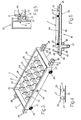
- an installation for working metal sheet 2 is generally indicated 1 and includes a laser unit 3 and an assembly 4 for storing the sheets 2.
- the assembly 4 includes a first store 5, of a vertical-stacking type with a plurality of shelves 6 one above the other. Pallets 7 are housed on the shelves 6, each carrying a metal sheet 2.
- the assembly 4 also includes a second store 8, exactly like the store 5 and facing it.
- the laser unit is carried by a working frame 11 similar to the stores 5 and 8.
- the frame 11, positioned along a horizontal axis M between the two stores 5 and 8, is of vertical construction but is not high, comprising only three shelves 12 on which to place respective pallets 7.
- the assembly 4 includes a device 13 for transferring the pallets 7 along the axis M from the store 5 to the frame 11 and back and a device 14 (similar to the device 13) for transferring the pallets 7 along the axis M from the store 8 to the frame 11 and back.
- the stores 5 and 8 include four vertical members: those indicated 15 face the frame 11 and those indicated 16 face in the opposite direction.
- Each shelf 6 is constituted by two horizontal rails 17, parallel to the axis M and supported by the vertical members 16 and 16.
- each shelf 6 has a first rail 17 supported by a first vertical member 15 and a first vertical member 16, and a second rail 17 supported by a second vertical member 15 and a second vertical member 16.
- the frame 11 includes four upright members 18, two aligned with the first vertical member 15 and the first vertical member 16 of the two stores 5 and 8, and two aligned with the second vertical member 15 and the second vertical member 16 of the stores 5 and 8.
- the shelves 12 of the frame 11 are similar to the shelves 6 of the stores 5 and 8 since they are also constituted by two horizontal rail 17 supported by the uprights 18 and aligned with the rail 17 of the stores 5 and 8.
- each pallet 7 is box-shaped and has four sides lying in respective vertical planes and arranged in parallel pairs; two parallel sides 22 are lateral and two parallel sides 22 correspond to the front or back, depending on which store houses the said pallet 7.
- the pallet 7 includes a base 23 and a plurality of horizontal railss 24 connecting the sides 21.
- the rail 24 each support a plurality of bodies 25 which end in pointed tops.
- the sheet 2 rests on the points of the bodies 25 forming a lid to the pallet 7; the points of the bodies 25 define a horizontal plane substantially at the same height as the upper edges of the sides 21 and 22.
- Two horizontal rods 26 protrude from the outer face of each side 21 respectively, on each of which a wheel 27 is freely rotatable.
- Each pallet 7 rests on its wheels 27 on the rail 17 of a respective shelf 6 or 12. It is clear from the shape of the stores 5 and 8 and the pallets 7, as described above, that the said pallets 7 can enter and leave the stores 5 and 8 either at the front or the back of the latter and can slide on the shelves 6 or 2.
- two pairs of parallel projections 28 extend from each side 22 parallel to the axis M.
- the projections 28 lie in respective vertical planes and each have two notches 29 and 30 along their lower edge; the notch 29 being nearest the side 22.
- the notches 29 and the notches 30 in both pairs of projections 28 are respectively aligned.
- the projections 28 extend beyond the space enclosed by the uprights 15 and 16 and, in particular, the notch 29 in the projection 28 extending from the front side 22 are outside the said space delimited by the uprights 15.
- the device 13 has a frame 31 for supporting a pallet 7.
- the device includes two horizontal bars 32, parallel to each other and to the axis M; the distance between the bars 32 being less than that between the rails 17 of the store 5.
- the two bars 32 are fixed to each other by two horizontal connecting members 33.
- each bar 32 carries on its outer surface a rail 34 aligned with a corresponding rail 17.
- the device 13 also includes a system 35 for moving the frame 31 along a vertical axis in order to take the said frame 31 from a first load/unload position in which the frame 31 is at the same level as one of the shelves 6 and a second load/unload position in which the frame 31 is at the same level as one of the shelves 12.
- the system 35 includes two U-shaped bodies 36, each fitted to a respective vertical member 15 which acts as guide during movement of the corresponding body 36, a motor 37 and a chain mechanism 38 operable to transmit drive from the motor 37 to the bodies 36; the frame 31 is securely fixed to the bodies 36.
- the bars 32 are of sufficient length to cover the distance between the vertical members 15 of the store 5 and the nearest vertical members 18 of the frame 11; in particular, a first axial end of the bars 32 is substantially adjacent the corresponding member 15 and the second axial end of the bar 32 is substantially adjacent the said corresponding upright 18.
- the device 13 finally includes a system 41 for collecting a pallet 7 from the store 5 and operable to transfer the said pallet 7 first to the frame 31 and then to the work frame 11.
- the system 41 is also operable to collect the pallet 7 from the frame 11 and return it to the store 5.
- the system 41 includes a chain 42 supported by a plate 43 carried by the bar 32 inside the space delimited between the bars 32; the plate 43 lies in a vertical plane.
- the chain 42 has a straight upper portion 44 parallel to the axis M and sliding on an edge of the plate 43, a lower portion 45 which includes a straight portion which slides along the plate 43 and two portions 46 connecting the portions 44 and 45 and sliding on respective axial ends of the plate 43, this end being rounded.
- the first connecting portion is near the said first end of the bar 32 and the second portion 46 is near the said second end of the bar 32; the portion 44 is substantially the same length as the bar 32.
- a part of the lower portion 45 is U shaped as it meshes with a toothed wheel 47 and two idlers 48 are applied to this portion.
- the wheel 47 corresponding to one bar 32 is fixed for rotation with the wheel 47 of the second bar 32 of the device 13, by means of a transmission shaft 51 which is rotated by an electric motor 52.
- the wheels 47 are keyed on the shaft 51, the longitudinal axis of which is horizontal and orthogonal to the axis M.
- Each chain 42 supports two assemblies, each having three horizontal pins 53 extending from either side of the chain 42 itself; a first assembly of three pins 53 is arranged along a first portion of the chain 42 and a second assembly of three pins is arranged along a second portion of the chain 42.
- the two aforesaid portions of the chain 42 are spaced by a distance equal to the distance between the slot 29 of the front side 22 and the slot 30 of the rear side 22 of the same pallet 7.
- the width of the chain 42 is less than the width of the space enclosed between a pair of projections 28, while the three pins 53 of each assembly are longer than the distance between the two projections 28 in a pair.
- the distance between the first and the last pins 53 of a same assembly is smaller than the length of the slots 29 and 30.
- the device 14 is entirely similar to the device 13 and its parts are therefore indicated by the same numerals used to indicate the components of the device 13.
- the machine 3 includes:
- the installation 1 includes a system 59 for the aspiriation of the fumes which form inside the pallet 7 during the laser working.
- the system 59 includes an extractor 60, two ducts 61 arranged along a first side portion of the frame 11 and along a second side portion thereof opposite the first, each duct having three apertures, one for each shelf 12, and two tubes 63 connecting the ducts 61 to the extractor 60.
- Each pallet 7 also has an opening 64 in each side 21, each opening 64 facing a respective opening 62 when the pallet is positioned on a shelf 12.
- the installation 1 finally includes two stations 65 for loading/unloading one pallet at a time, one station for the store 5 and one for the store 8.
- the stations 65 are arranged alongside the stores 5 and 8, adjacent the vertical members 16.
- Each station 65 includes a frame 66 for supporting a pallet 7; the frame 66 comprises two bars 67, parallel to each other and to the axis M, and a plurality of rails 68 connecting the bars 67.
- the wheels 27 of the pallet supported by the frame rest on the upper surfaces of the bars 67.
- the station 65 also includes means 71 for moving the frame 66 between a lower position and a position corresponding to one of the shelves 6; these means 71 are preferably constituted by fluid-dynamic actuators as shown in Figure 2.
- the installation 1 finally includes an electronic central control unit 74 which controls the operation of all the members, devices and systems making up the installation 1.
- the control unit 74 is also operable to identify which shelves 6 and 12 of the stores 5 and 8 and of the frame 11 house a pallet 7, which shelves 6 and 12 are vacant at any time, which pallets 7 are in transit and their position along the assembly 4, and which pallets 7 hold sheets 2 to be worked and which pallets 7 hold already-worked sheets 2.
- the installation 1 operates as follows.
- the device 13 is operable to collect a pallet 7 from one of the shelves 6 and to transfer it to the frame 11.
- the unit 74 controls the device 13 so that the frame 31 moves to the same level as the selected shelf 6.
- the system 41 is activated in order to move the chain 42 (clockwise looking at Figure 6). As shown in Figure 1, each chain 42 is arranged in a space between the projections 8 of a corresponding pair of projections 28.
- the first pallet 7 is placed on the highest shelf 12 and, as soon as the said pallet 7 is in position on the frame 11, the laser unit 57 of the machine 3 begins work on the sheet 2, work which consists in cutting parts of the sheet 2.
- the unit 57 is able to move along the axes X and Y under the action of the means 58a and 58b, and along the axis M thanks to movement of the cross member 55 under the action of the means 56.
- the device 13 collects one pallet 7 at a time placing them on the other shelves 12. Once work is finished on the sheet 2 on the pallet 7 resting on the top shelf 12, the device 13 removes the said pallet from the frame 11 and returns it to the store 5.
- the unit 57 is immediately able to begin work on the sheet 2 on the pallet 7 housed on the second shelf 12.
- the device 13 removes the pallet 7 from the second shelf 12 so that the unit 57 can begin work on the sheet 2 on the pallet 7 housed on the lower shelf 12. The operations described above in relation to the store 5 and the device 13 are repeated for the store 8 by the device 14.
- the assembly 4 has two stores 5 and 8, with a plurality of shelves 6, and two devices 13 and 14 for collecting and transferring the pallets 7, it can carry out a large number of combinations for supplying the frame 11 with pallets 7 holding sheets 2 to be worked and for removing the pallets 7.
- the pallets 7 holding already worked sheets 2 can be moved to the store 5 and/or 8 and then exchanged, by the stations 65, for pallets holding sheets 2 to be worked.
- the pallets 7 are removed from or placed on a shelf 6 by hand; it is clear, however, that such operations could also be carried out by devices entirely similar to the devices 13 and 14 described above.
- the machine 3 could have its own station, entirely separate from the device 13 and 14, for unloading from the frame 11 the pallets 7 holding already worked sheets 2, so that the stores 5 and 8 could be used only for supplying pallets 7 holding sheets 2 to be worked.
- the fumes that are produced in the pallet 7 while the unit 57 is carrying out the work are evacuated from the pallet 7 by the system 59.
- the plant 1 includes an assembly 4 which automatically manages the operations involved in handling the sheets 2 to be worked and those which have been worked.
- the use of very capacious stores 5 and 8 means that the installation 1 is able to operate even with few personnel, such personnel possibly being used to unload and load the pallets 7 from and into the stores 5 and 8.
- the structure and the operating characteristics of the assembly 4 mean that the idle time of the machine 3 is reduced. While a sheet 2 is being worked, the assembly 4 prepares pallets 7 on the other shelves 12 of the of the frame 11. This means a considerable reduction in the processing costs of the sheet metal.
Landscapes
- Physics & Mathematics (AREA)
- Optics & Photonics (AREA)
- Engineering & Computer Science (AREA)
- Mechanical Engineering (AREA)
- Plasma & Fusion (AREA)
- Warehouses Or Storage Devices (AREA)
Priority Applications (1)
| Application Number | Priority Date | Filing Date | Title |
|---|---|---|---|
| EP99830093A EP1031397A1 (de) | 1999-02-23 | 1999-02-23 | Eine Einrichtung zur Bearbeitung von Blechen |
Applications Claiming Priority (1)
| Application Number | Priority Date | Filing Date | Title |
|---|---|---|---|
| EP99830093A EP1031397A1 (de) | 1999-02-23 | 1999-02-23 | Eine Einrichtung zur Bearbeitung von Blechen |
Publications (1)
| Publication Number | Publication Date |
|---|---|
| EP1031397A1 true EP1031397A1 (de) | 2000-08-30 |
Family
ID=8243284
Family Applications (1)
| Application Number | Title | Priority Date | Filing Date |
|---|---|---|---|
| EP99830093A Withdrawn EP1031397A1 (de) | 1999-02-23 | 1999-02-23 | Eine Einrichtung zur Bearbeitung von Blechen |
Country Status (1)
| Country | Link |
|---|---|
| EP (1) | EP1031397A1 (de) |
Cited By (5)
| Publication number | Priority date | Publication date | Assignee | Title |
|---|---|---|---|---|
| US6606531B1 (en) | 2002-02-07 | 2003-08-12 | Trumpf, Inc. | Sheet material loader/unloader for machine tools |
| EP2060358A1 (de) * | 2007-11-14 | 2009-05-20 | Rainer S.r.l. | Laserschneidmaschine für Metallbleche |
| CN102858487A (zh) * | 2010-04-22 | 2013-01-02 | 通快机床两合公司 | 用于热加工工件的机器设备 |
| JP2014018817A (ja) * | 2012-07-17 | 2014-02-03 | Free Space Engineering Co Ltd | ワーク加工搬送システム |
| KR20170137903A (ko) * | 2015-04-20 | 2017-12-13 | 트룸프 베르크초이그마쉬넨 게엠베하 + 코. 카게 | 공작물 지지체를 갖는 공작 기계 및 공작 기계의 공작물 지지체에 대한 로딩 및 언로딩 방법 |
Citations (3)
| Publication number | Priority date | Publication date | Assignee | Title |
|---|---|---|---|---|
| DE3149864A1 (de) * | 1980-12-16 | 1982-06-24 | Nissan Motor Co., Ltd., Yokohama, Kanagawa | "montagevorrichtung fuer kraftfahrzeuge" |
| EP0511508A1 (de) * | 1991-04-03 | 1992-11-04 | Kiwa Giken Kabushiki Kaisha | Laser-Bearbeitungszentrum |
| WO1997003787A1 (de) * | 1995-07-20 | 1997-02-06 | Thyssen Industrie Ag | Verfahren zum schneiden und/oder verschweissen von blechen und bearbeitungsanlage zur durchführung des verfahrens |
-
1999
- 1999-02-23 EP EP99830093A patent/EP1031397A1/de not_active Withdrawn
Patent Citations (3)
| Publication number | Priority date | Publication date | Assignee | Title |
|---|---|---|---|---|
| DE3149864A1 (de) * | 1980-12-16 | 1982-06-24 | Nissan Motor Co., Ltd., Yokohama, Kanagawa | "montagevorrichtung fuer kraftfahrzeuge" |
| EP0511508A1 (de) * | 1991-04-03 | 1992-11-04 | Kiwa Giken Kabushiki Kaisha | Laser-Bearbeitungszentrum |
| WO1997003787A1 (de) * | 1995-07-20 | 1997-02-06 | Thyssen Industrie Ag | Verfahren zum schneiden und/oder verschweissen von blechen und bearbeitungsanlage zur durchführung des verfahrens |
Cited By (6)
| Publication number | Priority date | Publication date | Assignee | Title |
|---|---|---|---|---|
| US6606531B1 (en) | 2002-02-07 | 2003-08-12 | Trumpf, Inc. | Sheet material loader/unloader for machine tools |
| EP2060358A1 (de) * | 2007-11-14 | 2009-05-20 | Rainer S.r.l. | Laserschneidmaschine für Metallbleche |
| CN102858487A (zh) * | 2010-04-22 | 2013-01-02 | 通快机床两合公司 | 用于热加工工件的机器设备 |
| CN102858487B (zh) * | 2010-04-22 | 2015-09-09 | 通快机床两合公司 | 用于热加工工件的机器设备 |
| JP2014018817A (ja) * | 2012-07-17 | 2014-02-03 | Free Space Engineering Co Ltd | ワーク加工搬送システム |
| KR20170137903A (ko) * | 2015-04-20 | 2017-12-13 | 트룸프 베르크초이그마쉬넨 게엠베하 + 코. 카게 | 공작물 지지체를 갖는 공작 기계 및 공작 기계의 공작물 지지체에 대한 로딩 및 언로딩 방법 |
Similar Documents
| Publication | Publication Date | Title |
|---|---|---|
| EP4023570B1 (de) | Sortierroboter und sortierverfahren | |
| US9120623B2 (en) | Storage shelf system for storing storage goods | |
| CA2695502C (en) | Storage rack having transport device | |
| EP2186754A1 (de) | Kommissionieranlage und Verfahren zum Betreiben derselben mit einem Kommissionierwagen | |
| JP2008285251A (ja) | 板材搬送収納システムおよび板材搬送収納方法 | |
| EP0253790B1 (de) | Verfahren und Vorrichtung zur Übertragung von Artikeln | |
| EP2527080B1 (de) | Bearbeitungszentrum mit Stütz- und Bewegungssystem | |
| EP1023954A1 (de) | Vorrichtung zum Formen von Blechteilen | |
| EP0522172B1 (de) | Stangentransporteinrichtung | |
| CN112645047B (zh) | 自动上下料装置 | |
| EP0263988B1 (de) | Regalanordnung | |
| PL179842B1 (pl) | Urzadzenie do formowania metalowych przedmiotów i sposób formowania metalowych przedmiotów PL PL PL PL PL PL | |
| EP0329600B1 (de) | Regalanlage für die Bücher einer Bibliothek | |
| EP1266181B1 (de) | Senkrecht angeordneter ofen | |
| US5536129A (en) | Apparatus for transferring long stock between positions associated with storage and processing stations | |
| CN210279893U (zh) | 一种泛用型缓存收板机 | |
| CN218312254U (zh) | 自动上下料开料机 | |
| CN220641245U (zh) | 一种立库以及应用该立库的生产线 | |
| CN217512490U (zh) | 一种推载板装置和超声清洗系统 | |
| CN216638196U (zh) | 收料装置 | |
| CN212332753U (zh) | 一种零件冷热加工转运工装 | |
| JP2631909B2 (ja) | 荷物移載装置 | |
| JP2823745B2 (ja) | レーザ加工システムにおけるワークの処理方法及びその装置 | |
| JPH02142631A (ja) | プレス成形部品の積込み装置 | |
| JPH0569908A (ja) | ワーク自動整列収容装置 |
Legal Events
| Date | Code | Title | Description |
|---|---|---|---|
| PUAI | Public reference made under article 153(3) epc to a published international application that has entered the european phase |
Free format text: ORIGINAL CODE: 0009012 |
|
| 17P | Request for examination filed |
Effective date: 20000207 |
|
| AK | Designated contracting states |
Kind code of ref document: A1 Designated state(s): DE GB IT |
|
| AX | Request for extension of the european patent |
Free format text: AL;LT;LV;MK;RO;SI |
|
| AKX | Designation fees paid |
Free format text: DE GB IT |
|
| STAA | Information on the status of an ep patent application or granted ep patent |
Free format text: STATUS: THE APPLICATION IS DEEMED TO BE WITHDRAWN |
|
| 18D | Application deemed to be withdrawn |
Effective date: 20020903 |