EP1031669B1 - Cadres de profilés en sigma pour bâtiments - Google Patents
Cadres de profilés en sigma pour bâtiments Download PDFInfo
- Publication number
- EP1031669B1 EP1031669B1 EP99200494A EP99200494A EP1031669B1 EP 1031669 B1 EP1031669 B1 EP 1031669B1 EP 99200494 A EP99200494 A EP 99200494A EP 99200494 A EP99200494 A EP 99200494A EP 1031669 B1 EP1031669 B1 EP 1031669B1
- Authority
- EP
- European Patent Office
- Prior art keywords
- web
- frame
- longitudinal
- structural elements
- flanges
- Prior art date
- Legal status (The legal status is an assumption and is not a legal conclusion. Google has not performed a legal analysis and makes no representation as to the accuracy of the status listed.)
- Expired - Lifetime
Links
- 210000002105 tongue Anatomy 0.000 claims abstract description 70
- 239000000463 material Substances 0.000 claims abstract description 20
- 238000010276 construction Methods 0.000 claims description 4
- 230000003014 reinforcing effect Effects 0.000 claims description 3
- 238000004519 manufacturing process Methods 0.000 abstract 1
- 229910000831 Steel Inorganic materials 0.000 description 5
- 239000002184 metal Substances 0.000 description 5
- 239000010959 steel Substances 0.000 description 5
- 238000002360 preparation method Methods 0.000 description 4
- 238000005452 bending Methods 0.000 description 3
- 229910052799 carbon Inorganic materials 0.000 description 3
- 238000005304 joining Methods 0.000 description 3
- 238000000034 method Methods 0.000 description 3
- 239000000758 substrate Substances 0.000 description 3
- 230000015572 biosynthetic process Effects 0.000 description 2
- 238000009434 installation Methods 0.000 description 2
- 238000003466 welding Methods 0.000 description 2
- OKTJSMMVPCPJKN-UHFFFAOYSA-N Carbon Chemical compound [C] OKTJSMMVPCPJKN-UHFFFAOYSA-N 0.000 description 1
- 229920002430 Fibre-reinforced plastic Polymers 0.000 description 1
- 230000001154 acute effect Effects 0.000 description 1
- 238000000576 coating method Methods 0.000 description 1
- 238000005097 cold rolling Methods 0.000 description 1
- 230000007797 corrosion Effects 0.000 description 1
- 238000005260 corrosion Methods 0.000 description 1
- 239000011151 fibre-reinforced plastic Substances 0.000 description 1
- 238000005246 galvanizing Methods 0.000 description 1
- 239000003365 glass fiber Substances 0.000 description 1
- 238000012986 modification Methods 0.000 description 1
- 230000004048 modification Effects 0.000 description 1
- 239000003973 paint Substances 0.000 description 1
- 239000006223 plastic coating Substances 0.000 description 1
- 238000004080 punching Methods 0.000 description 1
- 238000000638 solvent extraction Methods 0.000 description 1
Images



Classifications
-
- E—FIXED CONSTRUCTIONS
- E04—BUILDING
- E04B—GENERAL BUILDING CONSTRUCTIONS; WALLS, e.g. PARTITIONS; ROOFS; FLOORS; CEILINGS; INSULATION OR OTHER PROTECTION OF BUILDINGS
- E04B9/00—Ceilings; Construction of ceilings, e.g. false ceilings; Ceiling construction with regard to insulation
- E04B9/06—Ceilings; Construction of ceilings, e.g. false ceilings; Ceiling construction with regard to insulation characterised by constructional features of the supporting construction, e.g. cross section or material of framework members
- E04B9/12—Connections between non-parallel members of the supporting construction
- E04B9/127—Connections between non-parallel members of the supporting construction one member being discontinuous and abutting against the other member
-
- E—FIXED CONSTRUCTIONS
- E04—BUILDING
- E04B—GENERAL BUILDING CONSTRUCTIONS; WALLS, e.g. PARTITIONS; ROOFS; FLOORS; CEILINGS; INSULATION OR OTHER PROTECTION OF BUILDINGS
- E04B1/00—Constructions in general; Structures which are not restricted either to walls, e.g. partitions, or floors or ceilings or roofs
- E04B1/18—Structures comprising elongated load-supporting parts, e.g. columns, girders, skeletons
- E04B1/24—Structures comprising elongated load-supporting parts, e.g. columns, girders, skeletons the supporting parts consisting of metal
-
- E—FIXED CONSTRUCTIONS
- E04—BUILDING
- E04B—GENERAL BUILDING CONSTRUCTIONS; WALLS, e.g. PARTITIONS; ROOFS; FLOORS; CEILINGS; INSULATION OR OTHER PROTECTION OF BUILDINGS
- E04B1/00—Constructions in general; Structures which are not restricted either to walls, e.g. partitions, or floors or ceilings or roofs
- E04B1/38—Connections for building structures in general
- E04B1/58—Connections for building structures in general of bar-shaped building elements
- E04B1/5806—Connections for building structures in general of bar-shaped building elements with a cross-section having an open profile
- E04B1/5818—Connections for building structures in general of bar-shaped building elements with a cross-section having an open profile of substantially U - form
-
- E—FIXED CONSTRUCTIONS
- E04—BUILDING
- E04B—GENERAL BUILDING CONSTRUCTIONS; WALLS, e.g. PARTITIONS; ROOFS; FLOORS; CEILINGS; INSULATION OR OTHER PROTECTION OF BUILDINGS
- E04B5/00—Floors; Floor construction with regard to insulation; Connections specially adapted therefor
- E04B5/02—Load-carrying floor structures formed substantially of prefabricated units
- E04B5/14—Load-carrying floor structures formed substantially of prefabricated units with beams or girders laid in two directions
-
- E—FIXED CONSTRUCTIONS
- E04—BUILDING
- E04B—GENERAL BUILDING CONSTRUCTIONS; WALLS, e.g. PARTITIONS; ROOFS; FLOORS; CEILINGS; INSULATION OR OTHER PROTECTION OF BUILDINGS
- E04B1/00—Constructions in general; Structures which are not restricted either to walls, e.g. partitions, or floors or ceilings or roofs
- E04B1/18—Structures comprising elongated load-supporting parts, e.g. columns, girders, skeletons
- E04B1/24—Structures comprising elongated load-supporting parts, e.g. columns, girders, skeletons the supporting parts consisting of metal
- E04B1/2403—Connection details of the elongated load-supporting parts
- E04B2001/2415—Brackets, gussets, joining plates
-
- E—FIXED CONSTRUCTIONS
- E04—BUILDING
- E04B—GENERAL BUILDING CONSTRUCTIONS; WALLS, e.g. PARTITIONS; ROOFS; FLOORS; CEILINGS; INSULATION OR OTHER PROTECTION OF BUILDINGS
- E04B1/00—Constructions in general; Structures which are not restricted either to walls, e.g. partitions, or floors or ceilings or roofs
- E04B1/18—Structures comprising elongated load-supporting parts, e.g. columns, girders, skeletons
- E04B1/24—Structures comprising elongated load-supporting parts, e.g. columns, girders, skeletons the supporting parts consisting of metal
- E04B1/2403—Connection details of the elongated load-supporting parts
- E04B2001/2448—Connections between open section profiles
-
- E—FIXED CONSTRUCTIONS
- E04—BUILDING
- E04B—GENERAL BUILDING CONSTRUCTIONS; WALLS, e.g. PARTITIONS; ROOFS; FLOORS; CEILINGS; INSULATION OR OTHER PROTECTION OF BUILDINGS
- E04B1/00—Constructions in general; Structures which are not restricted either to walls, e.g. partitions, or floors or ceilings or roofs
- E04B1/18—Structures comprising elongated load-supporting parts, e.g. columns, girders, skeletons
- E04B1/24—Structures comprising elongated load-supporting parts, e.g. columns, girders, skeletons the supporting parts consisting of metal
- E04B1/2403—Connection details of the elongated load-supporting parts
- E04B2001/2454—Connections between open and closed section profiles
-
- E—FIXED CONSTRUCTIONS
- E04—BUILDING
- E04B—GENERAL BUILDING CONSTRUCTIONS; WALLS, e.g. PARTITIONS; ROOFS; FLOORS; CEILINGS; INSULATION OR OTHER PROTECTION OF BUILDINGS
- E04B1/00—Constructions in general; Structures which are not restricted either to walls, e.g. partitions, or floors or ceilings or roofs
- E04B1/18—Structures comprising elongated load-supporting parts, e.g. columns, girders, skeletons
- E04B1/24—Structures comprising elongated load-supporting parts, e.g. columns, girders, skeletons the supporting parts consisting of metal
- E04B1/2403—Connection details of the elongated load-supporting parts
- E04B2001/2457—Beam to beam connections
-
- E—FIXED CONSTRUCTIONS
- E04—BUILDING
- E04B—GENERAL BUILDING CONSTRUCTIONS; WALLS, e.g. PARTITIONS; ROOFS; FLOORS; CEILINGS; INSULATION OR OTHER PROTECTION OF BUILDINGS
- E04B1/00—Constructions in general; Structures which are not restricted either to walls, e.g. partitions, or floors or ceilings or roofs
- E04B1/18—Structures comprising elongated load-supporting parts, e.g. columns, girders, skeletons
- E04B1/24—Structures comprising elongated load-supporting parts, e.g. columns, girders, skeletons the supporting parts consisting of metal
- E04B2001/2466—Details of the elongated load-supporting parts
- E04B2001/2472—Elongated load-supporting part formed from a number of parallel profiles
Definitions
- the present invention relates to elongate structural elements which may be fitted together to form a frame which may be used in the construction of buildings, e.g. for the construction of floors, intermediate platforms and ceilings, vertical walls including external, internal and partitioning walls or portal or roof frames.
- a structural element for erecting buildings, and also for erecting building models is described in DE 3 532 846 including a bar-type frame having a U-profile, which is open at the top, as base profile and a U-profile, which is open at the bottom, as top profile and also having posts and struts which connect base and top profiles and compromise a C-profile.
- the base profiles and the top profiles are configured such that they can be plugged together, and fixed, in each case at their ends via plug-in connectors to form a top frame corresponding to the building outline.
- the base profiles and the top profiles are provided in each case with a number of plug-in shoes which corresponds to the number of the posts provided, which shoes are held displaceably and fixedly on the relevant base or head profile and into which the posts are plugged by their free ends.
- DE 806 388 describes a method to couple crossing U-profiles.
- tongues are provided, to which the second profile is coupled by welding.
- FR 2 098 274 discloses a frame comprising two U-profiles, which web of the profile is provided with a number of tongues directed inwards the recess of the U-profile.
- Secondary profiles provided in a substantially perpendicular direction to the U-profiles, extend into the recess of the U-profile. The secondary profiles are coupled to the U-profiles by welding the outer ends of the secondary profiles to the tongues.
- the present invention provides a frame which can be easily and reliably put together on site, which involves less parts, in particular less small parts which can be easily dropped, provides a clean surface to the members of the frame uninterrupted by bolt heads and is strong and rigid.
- the present invention relates to a frame as claimed which includes elongate structural elements with a longitudinal web and at least two longitudinal flanges which extend away from the web at an angle, the flanges extending from the at least the same side of the web and the web and flanges forming a longitudinal recess between the flanges, and a plurality of transverse tongues spaced along the web and extending from the web into the recess, the tongues being formed integrally with, and from the same material as, the web.
- the tongues do not extend further than the envelope of the flanges and web which encloses the recess.
- the plane of the transverse tongues may be a right angles to the web.
- the frame comprises at least two first elongate structural elements, each first structural element having a longitudinal web and at least two longitudinal flanges which extend substantially at an angle form the web, the flanges extending from at least the same side of the web and the web and flanges forming a longitudinal recess between the flanges; a plurality of transverse tongues spaced along the web and extending from the web into the recess, the tongues being formed integrally with, and from the same material as, the web; and a plurality of second elongate structural element having two ends, each end of the second elongate structural element being connected directly to one of the tongues of one of the first structural elements.
- at least one of the outer longitudinal edges of second structural element is flush with an outer longitudinal edge of the first structural element.
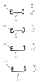
- Fig. 1 shows certain structural profiles which may be used with the present invention.
- Fig. 1A shows an "H"-profile
- Fig. B shows a "C"-profile made up of three socalled “Sigma”-profiles
- Fig. 1C shows a very simple “C”-profile in which the flanges 4 on both sides of the web 2 have the same length
- Fig. 1D shows a simple "C”-profile in which one flange 4A is larger than the other flange 4B.
- Fig. 1E to 1H show in cross section further structural profiles which may be used with the present invention.
- Fig. 1E is often referred to as a "C-plus”-profile
- Fig. 1F is a "C"-profile
- Fig. 1G is a "Sigma”-profile
- Fig. 1H is a "Sigma plus”-profile.
- All the profiles of Fig. 1 include a web 2 and two flanges 4 which extend away from the web 2 at substantially a right angle with respect to web 2.
- the two flanges 4 extend away from web 2 at least on one side of web 2.
- the web 2 need not be a completely flat web but may be corrugated or recessed either longitudinally or laterally in any suitable manner including the provision of holes.
- the flanges 4 may also include additional shapes such as longitudinal or lateral recesses or folds or seams or holes.
- the present invention also includes the use of "U"-profiles which may be looked upon as an arcuate web 2 with two flanges 4 attached thereto. Further, the present invention includes structural members with more than two flanges ( Fig. 1A may be considered to have four flanges).
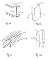
- Fig. 2 is a schematic representation of a first embodiment of the present invention.
- a structural element 6 (the main beam) has a profile similar to that described with respect to any of the profiles of Fig. 1 . It includes a web 2 and at least two flanges 4 which extend away from the web parallel to each other and substantially at right angles to web 2 when referred to the plane in which the web 2 lies as well as extending at right angles to the longitudinal axis of the element 6.
- the flanges 4 extend away from the web at least on one side of the web 2 to form a longitudinal recess therebetween.
- the structural element 6 is preferably a cold-rolled or cold-drawn metal profile, particularly one made of steel which may be galvanised or painted or coated with any suitable corrosion protection such as plastic coatings and including combinations of galvanising and paint.
- tongues 10 are formed in the web 2, for example by stamping and bending the web material to form each tongue 10.
- the tongue 10 is integral with web 2 and made from the same material.
- the join-line between tongue 10 and web 2 runs in the plane of the web 2 and substantially perpendicular to the longitudinal direction of the structural element 6. This will be referred to in accordance with the present invention as the provision of transverse tongues 10 in web 2.
- the tongue 10 is bent towards the side of web 2 from which the flanges 4 extend.
- the web material is a ductile material such as steel which allows such a bend without significant affect on the mechanical properties of the tongue 10.
- steel with a yield stress between 250 and 420 MPa is suitable.
- the profile of the main beam 6 has at least a longitudinal flat section between the two flanges 4 from which the tongues 10 may be easily formed. Particularly suitable profiles are "C”, “C-plus”, “Sigma” and “Sigma-plus”. As shown the plane in which tongue 10 lies is perpendicular to the longitudinal direction of structural element but the present invention is not limited thereto.
- the length of tongue 10 is not sufficient to extend beyond a line joining the ends or extremities of flanges 4. This means that the tongue 10 lies within the envelope defined by web 2 and flanges 4.
- structural element 6 may be placed flat onto a surface either with the outer side of the web 2 downwards on the substrate or the flanges 4 onto the substrate and tongue 10 will not touch, mark or damage any such substrate.
- the use of the web material of a main beam has the advantage that the tongue 10 has a material thickness which provides considerable mechanical strength. In the formation of a frame such as a wall, floor or ceiling frame about 80% of the frame is made from lighter weight secondary beams which join two main beams 6 together.
- main beams 6 The low percentage of main beams 6 means that these can be made from flat strip having a considerable thickness without increasing the overall weight of the frame significantly.
- the material used for a main beam 6 may be steel with a thickness of between 3 and 4mm whereas secondary joining beams may have a material thickness of between 1.5 and 2mm.
- the use of the web 2 of main beams 6 to form the tongues 10 is therefore superior to forming tongues or fastening tabs in the lighter gauge secondary beams.
- Tongues 10 may be provided with circular or oval fixing holes 11 or similar fixing devices which are preferably pre-punched in tongue 10 before it is stamped out and bent from web 2.
- the punching and bending of tongue 10 may be done in flat metal sheet prior to the cold-rolling process which forms the profile structural element 6 or tongue 10 may be stamped into web 2 and bent after profile structural element 6 has been formed.
- Secondary beam 8 In order to attach a secondary beam 8 at right angles to a main beam 6 as part of the construction of a rectangular frame the secondary beam 8 is bolted to the tongue 10.
- Secondary beam 8 has a sigma or sigma+ profile.
- the secondary beam 8 is be prepared so that it may slide into the recess formed by web 2 and flanges 4 of the main beam 6. As shown in Fig. 3A and 3B this is carried out by removing a portion of one of the flanges 14 so that secondary beam 8 slides into the recess formed between flanges 4 and web 2 of the main beam 6.
- Two or more suitably located holes 16 are provided which match holes 11 of tongue 10 and which may be used for securing the secondary beam 8 to the main beam 6 using bolts or rivets or similar.
- the preparation of the ends of the secondary beams 8 may be made in advance.
- the ends of the secondary beam 8 may be dimensioned so that the end face of secondary beam 8 abuts the inside of web 2.
- the length of tongue 10 may be relatively short.
- the asymmetrical end preparation of secondary beams 8 as shown in Figs. 3A and B allows one flange 14 (the upper one in the drawings) of the secondary beam 8 to be flush with the upper flange 4 of the main beam 6. This provides one flat surface, without bolt heads onto which a floor or ceiling boards may be laid or placed directly.
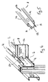
- a second embodiment of the present invention is shown schematically in Fig. 4 and 5 .
- the reference numerals used in Fig. 4 and 5 which are identical to the reference numbers of Fig. 2 and 3 relate to the same components.
- the main difference between the second embodiment and the first embodiment is shown in Fig. 5 and is caused by the fact that the secondary beam 8 has the same width as the main beam 6.
- Both flanges 14 of the secondary beam 8 are removed at an end portion in order to produce a jointing tab with holes 16 for connection to the tongue 10 through holes 11 of the main beam.
- the advantage of the second embodiment is that the secondary beam 8 is located symmetrically with respect to the main beam 6 whereas the secondary beam 8 of the first embodiment is not located symmetrically with respect to the main beam 6.
- both sides of a frame constructed in this manner are flat.
- the tab at the end of the secondary beam 8 which is connected to the tongue 10 may be less rigid than the similar tab for connection to the tongue 10 of the first embodiment because in the second embodiment both stiffening flanges 14 are removed.
- web 12 of the secondary member 8 in accordance with the second embodiment has itself a three-dimensional reinforcing structure so that the tab used for connection to tongue 10 maintains more rigidity than a simple flat sheet of metal. For this reason a profile such as a "Sigma" profile is used in the invention.
- the tongues 10 do not extend beyond the envelope formed by the flanges 4 and web 2 of the structural element 6, the tongue 10 is not easily damaged during transport. Additionally, structural elements 6 may be stacked together as shown in Fig. 7 in a nested way allowing the minimum volume for transport. The tongues 10 can be offset longitudinally to avoid tongues from two beams colliding directly.
- a further advantage of the present invention is that there are no bolt or rivet heads which project from the web 2 of the main beam 6 on the side which is remote from flanges 4.
- This allows frames 18 to be placed together as shown schematically in Fig. 6 .
- Each frame 18 consists of two main beams 6 attached by cross members 8 which are secondary beams and which are connected to the main beams 6 by the tongues 10 as has been described with respect to the first and second embodiments.
- the holes 12 may be alternatingly placed in front of and behind the tongue 10 in the longitudinal direction of the main beam 6.
- the end of a main beam 6 may be chosen so that a hole 12 is removed when the main beam 6 is cut to length leaving the tongue 10 firmly attached to the main part of the web 2 immediately at the end of the main beam 6.
- These frames 18 may be placed together with no space between the abutting main members 6 as shown schematically in the enlarged cross section of the beams 6 joining in the centre of Fig. 6 .
- the lack of bolt heads means that other coatings, panels or materials may be applied to the outer surface of web 2 without being disturbed by bolt heads.
- Secondary beam 8 is joined directly to the tongue 10 which is a part of main beam 6. Hence, secondary beam 8 is joined directly to main beam 6. No loose connecting pieces other than bolts or rivets are used to form the frame 18 which reduces the number of parts, speeds up installation and avoids having to carry or fit structural connectors which may be a danger to others or may get lost or stolen or used on other jobs.
- a further advantage may be appreciated when the frame 18 is used horizontally as a floor support and carries a load, e.g. up to 500 kg/m 2 . Loads on the secondary beams 8 are transferred to the main beams 6 by means of transverse tongues 10. When frame 18 is used horizontally the transverse tongues 10 extend horizontally into the recess between flanges 4 with the plane of tongue 10 being vertical. The downward force on the tongue 10 by the secondary beam 8 is supported by the full width of the tongue 10 where it joins web 2.
- This design feature combined with the fact that the thickness of the main beam web 2 is preferably larger than the thickness of the secondary web 12 and that the distance of the bolts or rivets to the web 2 is small means that a frame 18 made in accordance with the present invention has a greater load bearing capability, alternatively can be made with lighter gauge material for a given maximum loading.
- a suitable cross-section profile of a main beam 6 is shown in Fig. 8 .
- the width W of the web 2 may be typically 140 to 350 mm and the width B of the flange 4 may be typically 60 to 120 mm
- the ratio W/B is preferably 2 or more, typically 2.5 to 5.
- the width of the tongue 8 is typically 30% to 60% of W.
- the length of the tongue Y is typically less than 70% of W, for example 30 to 70% W.
- the main beam profile is a C or C+ profile and the secondary beam has a Sigma or Sigma + profile.
- transverse tongues 10 has been described as extending at right angles to the web 2 into the recess between the flanges 4 but the present invention is not limited thereto.
- the plane of at least some of the transverse tongues 10 may be placed at a different angle. For instance, the plane may be placed at 45° or 60° to the web 2.
- These angled tongues 10 may be used to connect secondary beams 8 at an angle of 45° or 60° to the main beams 6, respectively while keeping the secondary beam 8 and the main beam 6 in the same plane. This may provide a locking or bracing of the frame 18 as it introduces a triangular structure so that it is more rigid with respect to lateral forces.
- the angled tongues 10 are made from the same material as the web 2 and only bent through an acute angle so that the holes 11 in the tongues 10 may be accessed through the holes 12 in web 2.
- Holes 12 may be used for other purposes, e.g. for cables pipes, and other services which need to be introduced under the floor or in the ceiling of a building.
- the invention has been described mainly with respect to a main beam with only two flanges on one side of the web.
- the present invention also includes the use of more than two flanges.
- the tongues 10 may be formed alternatingly extending into the longitudinal recess between the flanges on one side of the central web and in the recess between the flanges on the other side of the central web.
- the structural elements 6, 8 have been described as being made from metal but they may also be made from any suitable structural material, e.g. glass-fibre or carbon fibre reinforced plastics.
Landscapes
- Engineering & Computer Science (AREA)
- Architecture (AREA)
- Physics & Mathematics (AREA)
- Electromagnetism (AREA)
- Civil Engineering (AREA)
- Structural Engineering (AREA)
- Joining Of Building Structures In Genera (AREA)
- Rod-Shaped Construction Members (AREA)
- Floor Finish (AREA)
- Door And Window Frames Mounted To Openings (AREA)
- Greenhouses (AREA)
Claims (13)
- Cadre (18) comprenant :au moins deux éléments structurels allongés principaux (6), chaque élément structurel principal ayant au moins deux premières brides longitudinales (4) avec une première âme longitudinale (2) entre ces dernières, les premières brides longitudinales s'étendant sensiblement à angle droit par rapport à la première âme, les premières brides longitudinales s'étendant à partir d'au moins le même côté de la première âme, et la première âme et les brides formant une partie en retrait longitudinale entre les premières brides longitudinales ;une pluralité de languettes transversales (10) espacées le long de chaque première âme et s'étendant à partir de la première âme dans la partie en retrait, les languettes étant formées d'un seul tenant avec la première âme et de la même matière que cette dernière ;une pluralité d'éléments structurels allongés secondaires (S) maintenus entre les deux éléments structurels allongés principaux, chaque élément structurel allongé secondaire ayant deux extrémités, chaque extrémité d'un élément structurel allongé secondaire étant directement reliée à une des languettes d'un élément correspondant des éléments structurels principaux, les éléments structurels allongés secondaires ayant au moins deux secondes brides longitudinales (14) avec une seconde âme longitudinale (12) entre ces dernières, les secondes brides longitudinales s'étendant à partir du même côté et à angle droit par rapport à la seconde âme ;ledit cadre est caractérisé en ce que :l'élément allongé secondaire a un profil en « Sigma » ou en « Sigma + » ;une surface extérieure, distante de la seconde âme, d'au moins une des secondes brides longitudinales des éléments structurels allongés secondaires est alignée sur une surface extérieure, distante de la première âme, d'une bride correspondante des premières brides longitudinales ;une partie de l'au moins une des secondes brides longitudinales de la pluralité des éléments structurels allongés secondaires est enlevée au niveau de l'extrémité respective des éléments structurels allongés secondaires pour former des pattes, chaque patte s'étendant dans la partie en retrait longitudinale du premier élément structurel allongé correspondant, des trous (16) dans les pattes étant alignés sur des trous (11) dans les languettes auxquelles elles sont reliées pour connexion à un dispositif de fixation, et chaque patte incluant une structure de renfort tridimensionnelle.
- Cadre (18) selon la revendication 1, dans lequel les pattes et les languettes (10) sont reliées par des rivets ou des boulons.
- Cadre (18) selon la revendication 1 ou 2, dans lequel une surface extérieure de chacune des deux premières brides longitudinales est alignée sur une surface extérieure respective de chacune des secondes brides longitudinales.
- Cadre (18) selon l'une quelconque des revendications précédentes, dans lequel la structure de renfort tridimensionnelle est formée par l'âme de l'élément structurel allongé secondaire à profil en Sigma (8).
- Cadre (18) selon l'une quelconque des revendications précédentes, dans lequel la première âme (2) a une partie plate longitudinale entre les premières brides longitudinales (4), et les languettes transversales (10) sont faites à partir de la partie plate.
- Cadre (18) selon l'une quelconque des revendications précédentes, dans lequel l'élément structurel principal (6) a un profil en « H », en « C », en « C-plus », en « Sigma » ou en « Sigma-plus ».
- Cadre (18) selon l'une quelconque des revendications précédentes, dans lequel les languettes transversales (10) ne s'étendent pas dans la partie en retrait longitudinale plus loin que l'enveloppe des premières brides longitudinales (4) et de la première âme (2) qui englobe la partie en retrait.
- Cadre (18) selon l'une quelconque des revendications précédentes, dans lequel les surfaces extérieures de l'élément structurel principal (6) sont exemptes de têtes de boulon ou d'écrous ou de rivets.
- Cadre (18) selon l'une quelconque des revendications précédentes, dans lequel les faces d'extrémité des extrémités des éléments structurels secondaires (8) butent contre l'intérieur de la première âme (2) des éléments structurels principaux (6).
- Cadre (18) selon l'une quelconque des revendications précédentes, utilisé en tant que cadre porteur dans la structure d'un plancher, d'une paroi, d'un plafond, d'un portique ou d'une charpente de toiture d'un bâtiment.
- Cadre (18) selon l'une quelconque des revendications précédentes, dans lequel les éléments structurels allongés principaux (6) sont des éléments structurels allongés laminés à froid ou étirés à froid.
- Cadre (18) selon l'une quelconque des revendications précédentes, dans lequel les éléments structurels allongés principaux (6) ont une épaisseur de matière entre 3 mm et 4 mm.
- Cadre (18) selon l'une quelconque des revendications précédentes, dans lequel les éléments structurels allongés secondaires (8) ont une épaisseur de matière entre 1,5 mm et 2 mm.
Priority Applications (4)
| Application Number | Priority Date | Filing Date | Title |
|---|---|---|---|
| EP99200494A EP1031669B1 (fr) | 1999-02-22 | 1999-02-22 | Cadres de profilés en sigma pour bâtiments |
| AT99200494T ATE449887T1 (de) | 1999-02-22 | 1999-02-22 | Gebäuderahmen mit sigma-profilen |
| DE69941674T DE69941674D1 (de) | 1999-02-22 | 1999-02-22 | Gebäuderahmen mit Sigma-Profilen |
| ES99200494T ES2337638T3 (es) | 1999-02-22 | 1999-02-22 | Armazones para edificios con perfil en sigma. |
Applications Claiming Priority (1)
| Application Number | Priority Date | Filing Date | Title |
|---|---|---|---|
| EP99200494A EP1031669B1 (fr) | 1999-02-22 | 1999-02-22 | Cadres de profilés en sigma pour bâtiments |
Publications (2)
| Publication Number | Publication Date |
|---|---|
| EP1031669A1 EP1031669A1 (fr) | 2000-08-30 |
| EP1031669B1 true EP1031669B1 (fr) | 2009-11-25 |
Family
ID=8239907
Family Applications (1)
| Application Number | Title | Priority Date | Filing Date |
|---|---|---|---|
| EP99200494A Expired - Lifetime EP1031669B1 (fr) | 1999-02-22 | 1999-02-22 | Cadres de profilés en sigma pour bâtiments |
Country Status (4)
| Country | Link |
|---|---|
| EP (1) | EP1031669B1 (fr) |
| AT (1) | ATE449887T1 (fr) |
| DE (1) | DE69941674D1 (fr) |
| ES (1) | ES2337638T3 (fr) |
Cited By (1)
| Publication number | Priority date | Publication date | Assignee | Title |
|---|---|---|---|---|
| EP3521780B1 (fr) * | 2011-02-11 | 2023-11-01 | Siegfried Janner | Plate-forme de pesage |
Families Citing this family (13)
| Publication number | Priority date | Publication date | Assignee | Title |
|---|---|---|---|---|
| CA2401289C (fr) * | 2002-09-05 | 2011-07-26 | Bailey Metal Products Limited | Solive de plancher en metal |
| US8523150B2 (en) * | 2004-03-15 | 2013-09-03 | Edward L. Gibbs | Fence with tiltable picket |
| AU2005205833A1 (en) * | 2004-09-07 | 2006-03-30 | Aldo Bevacqua | A structural assembly |
| DE602006006412D1 (de) * | 2006-02-20 | 2009-06-04 | Corus Uk Ltd | Bodenelement |
| WO2007106923A1 (fr) * | 2006-03-20 | 2007-09-27 | Aldo Bevacqua | Ensemble structural |
| FI124126B (fi) * | 2010-12-29 | 2014-03-31 | Temet Oy | Paineventtiili ja venttiilikehysrakenne |
| GR1008587B (el) * | 2013-04-24 | 2015-10-14 | ΠΑΓΟΥΝΗ ΑΝΩΝΥΜΟΣ ΕΤΑΙΡΙΑ ΠΑΡΑΓΩΓΗΣ ΚΑΙ ΕΜΠΟΡΙΑΣ ΜΕΤΑΛΛΙΚΩΝ ΔΟΜΙΚΩΝ ΠΡΟΪΟΝΤΩΝ με δ.τ. "ΠΑΓΟΥΝΗ Α.Ε.", | Δομικο, πολυμορφικο συστημα, μεταλλικων, λεπτοτοιχων, ανοικτων, διατομων |
| USD916327S1 (en) * | 2019-08-23 | 2021-04-13 | Harbor Freight Tools Usa, Inc. | Storage cabinet trim piece |
| CN110965652B (zh) * | 2019-12-21 | 2021-02-12 | 闫相明 | 一种装配式建筑主次梁钢连接节点结构 |
| DE102021109959A1 (de) | 2021-04-20 | 2022-10-20 | Nedcon B.V. | Horizontalboden aus einer Tragkonstruktion und darauf verlegten Bodenplatten |
| CN114541578B (zh) * | 2022-02-26 | 2023-12-15 | 秦皇岛环亚设备股份有限公司 | 一种冲压连接件及其轻钢结构刚架 |
| IT202200010154A1 (it) * | 2022-05-17 | 2022-08-17 | Mario Mariotto | Sistema costruttivo sostenibile per edifici multipiano, di tipo prefabbricato a secco, con componenti riciclabili. |
| CN119378075A (zh) * | 2024-10-29 | 2025-01-28 | 中集建造(天津)有限公司 | 基于Tekla平台的建模方法 |
Family Cites Families (7)
| Publication number | Priority date | Publication date | Assignee | Title |
|---|---|---|---|---|
| NL63802C (fr) * | 1947-03-06 | 1949-02-15 | Alexandre Horowitz | |
| US3717964A (en) * | 1970-07-09 | 1973-02-27 | Behring Corp | Module frames |
| US4011707A (en) * | 1975-07-02 | 1977-03-15 | Armstrong Cork Company | Cross tee end joint for suspended ceiling system |
| AU2396177A (en) * | 1976-04-30 | 1978-10-12 | Webb D C | Interlocking building frame |
| FR2366414A1 (fr) * | 1976-10-01 | 1978-04-28 | Slowbe Joseph | Assemblage de construction |
| DE3532846C2 (de) | 1985-09-14 | 1995-05-04 | Gerhard Stroer | Bauelement zur Erstellung von Gebäuden, auch zur Erstellung von Gebäudemodellen |
| US5720138A (en) * | 1992-11-12 | 1998-02-24 | Johnson; David L. | Metallic wall framing, method and apparatus for producing same |
-
1999
- 1999-02-22 AT AT99200494T patent/ATE449887T1/de active
- 1999-02-22 EP EP99200494A patent/EP1031669B1/fr not_active Expired - Lifetime
- 1999-02-22 ES ES99200494T patent/ES2337638T3/es not_active Expired - Lifetime
- 1999-02-22 DE DE69941674T patent/DE69941674D1/de not_active Expired - Lifetime
Cited By (1)
| Publication number | Priority date | Publication date | Assignee | Title |
|---|---|---|---|---|
| EP3521780B1 (fr) * | 2011-02-11 | 2023-11-01 | Siegfried Janner | Plate-forme de pesage |
Also Published As
| Publication number | Publication date |
|---|---|
| DE69941674D1 (de) | 2010-01-07 |
| ES2337638T3 (es) | 2010-04-27 |
| EP1031669A1 (fr) | 2000-08-30 |
| ATE449887T1 (de) | 2009-12-15 |
Similar Documents
| Publication | Publication Date | Title |
|---|---|---|
| US6151858A (en) | Building construction system | |
| US6199336B1 (en) | Metal wall framework and clip | |
| EP1031669B1 (fr) | Cadres de profilés en sigma pour bâtiments | |
| US10179992B2 (en) | Heavy duty hanger for fire separation wall | |
| US6253529B1 (en) | Mounting plate for a partition system | |
| US20110219720A1 (en) | Adjustable floor to wall connectors for use with bottom chord and web bearing joists | |
| US5579622A (en) | Floor frame assembly | |
| EP2567035B1 (fr) | Améliorations apportées à des structures de construction évolutives | |
| US20140311082A1 (en) | Modular wall stud brace | |
| US9834940B2 (en) | Modular building structures improvements | |
| US20040255535A1 (en) | Multi-purpose construction assembly and method | |
| US8539730B2 (en) | Building system | |
| JP2004092154A (ja) | コンクリート型枠、及びその構築方法 | |
| GB2201184A (en) | Composite self propping beam for use as a lintel when forming an opening in an existing wall | |
| JP7312660B2 (ja) | 外壁パネル取り付け補助具及び外壁パネル取り付け方法 | |
| EP4153822B1 (fr) | Connecteur pour construction à sec, arrangement pour construction à sec, kit et méthode de construction d'un plafond pour construction à sec | |
| JP4711816B2 (ja) | 増設梁及び床パネルの補強方法 | |
| JP7335769B2 (ja) | コーナーカバー取り付け金具及びコーナーカバー取り付け方法 | |
| WO2015135054A1 (fr) | Entretoise de poteau mural modulaire | |
| JP7278131B2 (ja) | 外壁パネル取り付け方法 | |
| JP2020117879A (ja) | 木製横架材と鋼製横架材との接合構造および受け金物 | |
| JP7391587B2 (ja) | 外壁パネル取り付け補助具及び外壁パネル取り付け方法 | |
| JP2025180571A (ja) | 建物の取付構造 | |
| JPH06185121A (ja) | 組立式ユニットハウス及びその施工方法 | |
| JP3039613U (ja) | 取付金具 |
Legal Events
| Date | Code | Title | Description |
|---|---|---|---|
| PUAI | Public reference made under article 153(3) epc to a published international application that has entered the european phase |
Free format text: ORIGINAL CODE: 0009012 |
|
| AK | Designated contracting states |
Kind code of ref document: A1 Designated state(s): AT BE CH DE DK ES FR GB IT LI NL |
|
| AX | Request for extension of the european patent |
Free format text: AL;LT;LV;MK;RO;SI |
|
| 17P | Request for examination filed |
Effective date: 20010226 |
|
| AKX | Designation fees paid |
Free format text: AT BE CH DE DK ES FR GB IT LI NL |
|
| 17Q | First examination report despatched |
Effective date: 20051005 |
|
| GRAC | Information related to communication of intention to grant a patent modified |
Free format text: ORIGINAL CODE: EPIDOSCIGR1 |
|
| GRAP | Despatch of communication of intention to grant a patent |
Free format text: ORIGINAL CODE: EPIDOSNIGR1 |
|
| RTI1 | Title (correction) |
Free format text: BUILDING FRAMES WITH SIGMA-PROFILE |
|
| GRAS | Grant fee paid |
Free format text: ORIGINAL CODE: EPIDOSNIGR3 |
|
| GRAA | (expected) grant |
Free format text: ORIGINAL CODE: 0009210 |
|
| AK | Designated contracting states |
Kind code of ref document: B1 Designated state(s): AT BE CH DE DK ES FR GB IT LI NL |
|
| REG | Reference to a national code |
Ref country code: GB Ref legal event code: FG4D |
|
| REG | Reference to a national code |
Ref country code: CH Ref legal event code: EP |
|
| REF | Corresponds to: |
Ref document number: 69941674 Country of ref document: DE Date of ref document: 20100107 Kind code of ref document: P |
|
| REG | Reference to a national code |
Ref country code: NL Ref legal event code: T3 |
|
| REG | Reference to a national code |
Ref country code: ES Ref legal event code: FG2A Ref document number: 2337638 Country of ref document: ES Kind code of ref document: T3 |
|
| PG25 | Lapsed in a contracting state [announced via postgrant information from national office to epo] |
Ref country code: DK Free format text: LAPSE BECAUSE OF FAILURE TO SUBMIT A TRANSLATION OF THE DESCRIPTION OR TO PAY THE FEE WITHIN THE PRESCRIBED TIME-LIMIT Effective date: 20091125 |
|
| REG | Reference to a national code |
Ref country code: CH Ref legal event code: PL |
|
| PLBE | No opposition filed within time limit |
Free format text: ORIGINAL CODE: 0009261 |
|
| STAA | Information on the status of an ep patent application or granted ep patent |
Free format text: STATUS: NO OPPOSITION FILED WITHIN TIME LIMIT |
|
| PG25 | Lapsed in a contracting state [announced via postgrant information from national office to epo] |
Ref country code: LI Free format text: LAPSE BECAUSE OF NON-PAYMENT OF DUE FEES Effective date: 20100228 Ref country code: CH Free format text: LAPSE BECAUSE OF NON-PAYMENT OF DUE FEES Effective date: 20100228 |
|
| 26N | No opposition filed |
Effective date: 20100826 |
|
| PG25 | Lapsed in a contracting state [announced via postgrant information from national office to epo] |
Ref country code: IT Free format text: LAPSE BECAUSE OF FAILURE TO SUBMIT A TRANSLATION OF THE DESCRIPTION OR TO PAY THE FEE WITHIN THE PRESCRIBED TIME-LIMIT Effective date: 20091125 |
|
| PGFP | Annual fee paid to national office [announced via postgrant information from national office to epo] |
Ref country code: AT Payment date: 20130213 Year of fee payment: 15 |
|
| REG | Reference to a national code |
Ref country code: AT Ref legal event code: MM01 Ref document number: 449887 Country of ref document: AT Kind code of ref document: T Effective date: 20140222 |
|
| PG25 | Lapsed in a contracting state [announced via postgrant information from national office to epo] |
Ref country code: AT Free format text: LAPSE BECAUSE OF NON-PAYMENT OF DUE FEES Effective date: 20140222 |
|
| REG | Reference to a national code |
Ref country code: FR Ref legal event code: PLFP Year of fee payment: 18 |
|
| REG | Reference to a national code |
Ref country code: FR Ref legal event code: PLFP Year of fee payment: 19 |
|
| PGFP | Annual fee paid to national office [announced via postgrant information from national office to epo] |
Ref country code: DE Payment date: 20170131 Year of fee payment: 19 |
|
| PGFP | Annual fee paid to national office [announced via postgrant information from national office to epo] |
Ref country code: GB Payment date: 20170130 Year of fee payment: 19 |
|
| REG | Reference to a national code |
Ref country code: FR Ref legal event code: PLFP Year of fee payment: 20 |
|
| PGFP | Annual fee paid to national office [announced via postgrant information from national office to epo] |
Ref country code: FR Payment date: 20171220 Year of fee payment: 20 |
|
| PGFP | Annual fee paid to national office [announced via postgrant information from national office to epo] |
Ref country code: BE Payment date: 20171220 Year of fee payment: 20 |
|
| PGFP | Annual fee paid to national office [announced via postgrant information from national office to epo] |
Ref country code: NL Payment date: 20180227 Year of fee payment: 20 |
|
| PGFP | Annual fee paid to national office [announced via postgrant information from national office to epo] |
Ref country code: ES Payment date: 20180315 Year of fee payment: 20 |
|
| REG | Reference to a national code |
Ref country code: DE Ref legal event code: R119 Ref document number: 69941674 Country of ref document: DE |
|
| GBPC | Gb: european patent ceased through non-payment of renewal fee |
Effective date: 20180222 |
|
| PG25 | Lapsed in a contracting state [announced via postgrant information from national office to epo] |
Ref country code: DE Free format text: LAPSE BECAUSE OF NON-PAYMENT OF DUE FEES Effective date: 20180901 |
|
| REG | Reference to a national code |
Ref country code: NL Ref legal event code: MK Effective date: 20190221 |
|
| PG25 | Lapsed in a contracting state [announced via postgrant information from national office to epo] |
Ref country code: GB Free format text: LAPSE BECAUSE OF NON-PAYMENT OF DUE FEES Effective date: 20180222 |
|
| REG | Reference to a national code |
Ref country code: BE Ref legal event code: MK Effective date: 20190222 |
|
| REG | Reference to a national code |
Ref country code: ES Ref legal event code: FD2A Effective date: 20200723 |
|
| PG25 | Lapsed in a contracting state [announced via postgrant information from national office to epo] |
Ref country code: ES Free format text: LAPSE BECAUSE OF EXPIRATION OF PROTECTION Effective date: 20190223 |