EP1031675A2 - Profilstab für Tragsäule für freitragendes Dach und dgl. - Google Patents
Profilstab für Tragsäule für freitragendes Dach und dgl. Download PDFInfo
- Publication number
- EP1031675A2 EP1031675A2 EP99120688A EP99120688A EP1031675A2 EP 1031675 A2 EP1031675 A2 EP 1031675A2 EP 99120688 A EP99120688 A EP 99120688A EP 99120688 A EP99120688 A EP 99120688A EP 1031675 A2 EP1031675 A2 EP 1031675A2
- Authority
- EP
- European Patent Office
- Prior art keywords
- section bar
- column
- support columns
- profiled
- columns according
- Prior art date
- Legal status (The legal status is an assumption and is not a legal conclusion. Google has not performed a legal analysis and makes no representation as to the accuracy of the status listed.)
- Withdrawn
Links
Images






Classifications
-
- E—FIXED CONSTRUCTIONS
- E04—BUILDING
- E04C—STRUCTURAL ELEMENTS; BUILDING MATERIALS
- E04C3/00—Structural elongated elements designed for load-supporting
- E04C3/30—Columns; Pillars; Struts
- E04C3/32—Columns; Pillars; Struts of metal
-
- E—FIXED CONSTRUCTIONS
- E01—CONSTRUCTION OF ROADS, RAILWAYS, OR BRIDGES
- E01F—ADDITIONAL WORK, SUCH AS EQUIPPING ROADS OR THE CONSTRUCTION OF PLATFORMS, HELICOPTER LANDING STAGES, SIGNS, SNOW FENCES, OR THE LIKE
- E01F9/00—Arrangement of road signs or traffic signals; Arrangements for enforcing caution
- E01F9/60—Upright bodies, e.g. marker posts or bollards; Supports for road signs
- E01F9/623—Upright bodies, e.g. marker posts or bollards; Supports for road signs characterised by form or by structural features, e.g. for enabling displacement or deflection
-
- E—FIXED CONSTRUCTIONS
- E04—BUILDING
- E04H—BUILDINGS OR LIKE STRUCTURES FOR PARTICULAR PURPOSES; SWIMMING OR SPLASH BATHS OR POOLS; MASTS; FENCING; TENTS OR CANOPIES, IN GENERAL
- E04H17/00—Fencing, e.g. fences, enclosures, corrals
- E04H17/006—Caps or covers for posts
-
- B—PERFORMING OPERATIONS; TRANSPORTING
- B29—WORKING OF PLASTICS; WORKING OF SUBSTANCES IN A PLASTIC STATE IN GENERAL
- B29C—SHAPING OR JOINING OF PLASTICS; SHAPING OF MATERIAL IN A PLASTIC STATE, NOT OTHERWISE PROVIDED FOR; AFTER-TREATMENT OF THE SHAPED PRODUCTS, e.g. REPAIRING
- B29C2949/00—Indexing scheme relating to blow-moulding
- B29C2949/07—Preforms or parisons characterised by their configuration
- B29C2949/0715—Preforms or parisons characterised by their configuration the preform having one end closed
-
- B—PERFORMING OPERATIONS; TRANSPORTING
- B29—WORKING OF PLASTICS; WORKING OF SUBSTANCES IN A PLASTIC STATE IN GENERAL
- B29C—SHAPING OR JOINING OF PLASTICS; SHAPING OF MATERIAL IN A PLASTIC STATE, NOT OTHERWISE PROVIDED FOR; AFTER-TREATMENT OF THE SHAPED PRODUCTS, e.g. REPAIRING
- B29C49/00—Blow-moulding, i.e. blowing a preform or parison to a desired shape within a mould; Apparatus therefor
- B29C49/42—Component parts, details or accessories; Auxiliary operations
- B29C49/4205—Handling means, e.g. transfer, loading or discharging means
- B29C49/42073—Grippers
- B29C49/42075—Grippers with pivoting clamps
Definitions
- the present invention refers to a section bar for support columns for cantilever roofs and similar covering means, as well as for various uses, which is so shaped as to be able to be simply and quickly adapted to the various applications.
- Profiled columns used to support pre-fabricated roofings of various kind, as well as in various other applications, are largely known in the art. These are generally installed in an upright position and joined to the various parts forming each structure to be assembled, for instance with walls made of some metal or plastic material, usually by means of fastening and/or welding systems of a traditional type, which requires performing a number of complicated and expensive operations, thereby obtaining fixed structures that do not lend themselves to being subsequently disassembled and converted into structures of some other kind.
- a modular-type column section bar 10 is generally illustrated, which is adapted to be used both to support pre-fabricated roofings of various kind for sheltering from rainfalls and atmospheric precipitations in general (snow, hail and the like), such as for instance cantilever roofs, shelters, sheds, canopies, tunnels and the like, and in various other applications, such as for instance support members for road signs, advertising signs, waste collecting baskets and other town and road fitting items, dissuaders aimed at impeding the access of motor vehicles and/or motorcycles into pedestrian precincts, and the like, wherein said column section bar is to this purpose adapted to be repeatedly assembled and dissassembled from a type of structure to another one without requiring the use of any kind of rigid fastening means and/or weldings whatsoever.
- Figure 1 which illustrates such a metal column section bar 10
- the latter is essentially formed by an internally hollow, cylindrically shaped vertical column 11 having the desired height according to the intended application, which is provided with a corrugated outer surface 12 all over its circumference, a removable cap 13, which is adapted to be applied on to the corresponding open upper head 14 of said column, and a lower base 15 enabling the column section bar itself to rest on and be fastened to the ground in the required installation position thereof.
- the head cap 13 can be noticed to be perforated centrally on top in order to enable an elongated vertical member 16 to be attached thereto so as to be capable of sustaining a gutter 17 for collecting and disposing rain water, as well as atmospheric precipitations of various kind, such gutter being generally suitably attached against the perimetral sides of sheltering constructions of the most various kinds and being further described in detail in a separate patent application filed by the same Applicant. It will however be appreciated that such a head cap may also not be provided with such an elongated member 16, depending on the intended application.
- FIG. 1 in which the vertical column 11 is illustrated, the latter can be noticed to essentially consists of the assembly formed by at least an inner metal pole 18 of a tubular or polygonal shape (Figure 5), which forms the vertically extending support of the column section bar 10, and a shaped enclosing structure 19 which is sized to larger dimensions than the inner pole 18 and is arranged and fixed concentrically around the same pole.
- Figure 5 an inner metal pole 18 of a tubular or polygonal shape
- Figure 5 which forms the vertically extending support of the column section bar 10
- a shaped enclosing structure 19 which is sized to larger dimensions than the inner pole 18 and is arranged and fixed concentrically around the same pole.
- such an inner pole 18 is provided with an inner cavity 20 reaching all along the extension thereof, in the upper extremity of which the head cap 13 is inserted, and the lower extremity 21 of which is inserted, and suitably fastended, in a corresponding axial through-aperture 22 provided in the lower base 15 (see Figure 6) and extends downwards beyond the latter for a determined extent so as to be able to be driven into the ground, in the desired position and site of installation, to such a depth as required to keep and sustain the entire column section bar in its vertically erected position.
- Such an inner pole 18, further to acting as a support for the entire column section bar 10, is also used for enabling the further component parts used to form the various constructions being implemented to be assembled and fastened thereto.
- it is advantageously provided with perforations that are appropriately distributed all along its circumference and its height so as to enable said component parts to be assembled and fastened gainst such a pole in various positions and arrangements, as this will be described in greater detail further on.
- Figure 2 which particularly illustrates the shape of said enclosing structure 19, the latter can be noticed to essentially comprise an outer covering 23 enclosing the inner pole 18 and formed by thick walls of a heavy metal material and shaped in the form of a series of circular sectors 24 equally spaced from each other along the entire periphery of the vertical column 11, thereby defining a series of profiled cavities 25 with similar cross-section areas between one of said circular sectors 24 and the next one.
- the outer covering 23 is covered over its entire extension by a thin peripheral wall 26 featuring a corrugated outer surface, which is suitably fixed against said circular sectors 24 and the profiled cavities 25.
- each profiled cavity 25 is in turn shaped to feature a quadrangularly shaped contour with two T-shaped side protrusions 27, and is accessible through a front aperture 28 that is narrower than the cavity itself and extends throughout the height of the column 11, wherein a corresponding piece of closing wall 29, which also has a corrugated outer surface and sits flush with the remaining corrugated outer surface of the column 11, is inserted in such an aperture,
- a corresponding profiled frame 30, forming a sealing gasket of an appropriate material, eg. rubber, is capable of being removably snap-fitted in each such profiled cavity 25 after having first removed the related piece of closing wall 29 therefrom, wherein such a frame is fixed against the inner pole 18 by means of screws, bolts or similar fastening means 31 either passing through corresponding holes (not shown) provided in the same frame and the inner pole or appropriately tightened against the outer surface of said pole, said profiled frame being grooved and provided with elastically pliable borders 32 adapted to accomodate between them at least a component part of the sheltering construction to be implemented, such as for instance a partition wall of glass, plastics or some other clear material 33, so that each component part can so be mounted in a sealed, ie. water-tight manner in the profiled frame 30, while being supported by the column section bar according to the present invention.
- an appropriate material eg. rubber
- FIGS. 6 to 8 can now be noticed to schematically illustrate a lower resting base 15 of the column section bar according to the present invention, wherein it can again be noticed that it is constituted by a bottom block 38 having an enlarged and flattened circular or polygonal shape, provided with through-holes 39 for the insertion of bolts, tie-rods or other means for fastening the entire column section bar on to the ground, as well as a vertical bush 40, integral with said bottom block 40, of which it has essentially the same shape, but a smaller size, which extends upwards and is crossed axially by said central through-hole 22, in which there are provided inner protrusions 41 equally spaced from each other and adapted to snap into corresponding profiled cavities (not shown) of the inner pole 18 that is inserted into said through-hole and stuck to a certain depth into the ground, thereby sustaining the same pole.
- a bottom block 38 having an enlarged and flattened circular or polygonal shape, provided with through-holes 39 for the insertion of bolts, tie
- FIGS 9 to 12 can now be seen to illustrate a head cap 13, which is constituted essentially by a short lower stem 42, in which there is provided an axial blind hole 43, and a thin enlarged upper part 4 in the shape of a spherical cap, joined to said stem, wherein said stem is conformed to feature an outer profile that is adaptable to be removably inserted in the free inner space 45 of the vertical column 11, as defined between the various circular sectors 24 and profiled cavities 25 of the same column, and wherein said upper enlarged part is made thinner in its central top portion 46 coinciding with said blind hole 43, in such a manner as to make it possible for said head cap to be used as a terminal piece of the column section bar, without any need for the top portion 46 thereof to be perforated, such as for instance in the case of the head cap illustrated in Figures 8 and 28, or as a support and fastening member for an elongated vertical piece 16, by having in this case the top portion 46 of the same head cap perforated, thereby converting the blind hole
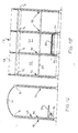
- Figures 13 and 14 illustrate the case of a tunnel or sheltered passage 47 for the connection of various buildings or pre-fabricated constructions with each other, comprising a double row of column section bars that are aligned with each other and sustain, with respective elongated pieces 16, laterally open, clear curved coverings 48.
- Figures 15 and 16 illustrate the same tunnel or sheltered connecting passage 47 shown in Figures 13 and 14, in which there is provided at least a clear lateral wall 49 joined with the curved covering 48, and against which there are fixed, through respective profiled support pieces 34, a bench 50 and a horizontal lath 51 for hanging items thereon.
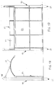
- Figures 17 and 18 illustrate a sheltering roof or canopy 52 for use at bus stops or similar places. with column section bars sustaining, in a cantilever-type construction, a clear curved covering 53 joined to a clear lateral wall 54, again through the use of elongated pieces 16.
- Figures 19 through to 26 schematically illustrate further versions of sheltering constructions sustained by column section bars according to the present invention, with the use of elongated pieces 16.
- these sheltering constructions are formed by a series (three) of curved coverings 55 that are joined side by side with each other ; in Figures 21 and 22 they are formed by a curved covering 55 sustained by a pair of column section bars at an extremity thereof and a common wall 56 at the other extremity thereof, in Figures 23 to 26 they can be noticed to be again formed by a series (three) of curved coverings 55, but without column section bars which are embedded in a common wall 56 in the case of Figures 23 and 24, and are further sustained in a cantilever manner by said common wall 56 by means of tie-rods 57.
- FIGS 27 through to 37 illustrate further possible applications of the column section bars according to the present invention.
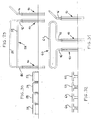
- Figures 29 through to 37 illustrate various types of so-called dissuaders, as used to enable pedestrian precincts, gardens, parks and the like to be acceded to selectively, ie. by people only, while impeding entrance to motor vehicles or even cycles, and making use of column incorporating elongated pieces 16.
- Figure 29 can be noticed to illustrate a dissuader 58 installed at the entrance of a restricted-access zone, formed by two column section bars placed at a distance from each other, the elongated pieces 16 of which are joined together by means of horizontal and rectilinear bars 59 impeding the access, and a further column section bar that is displaced with respect to the other two by such an interval as to just allow for people being able to pass therethrough.
- Figure 30 can be noticed to illustrate a series of identical dissuaders 58 which are slightly modified with respect to those shown in Figure 29 and are used in different positions along the periphery of restricted-access areas.
- Figure 31 illustrates another type of dissuader 60 intended for the same applications as the above cited ones, formed by two column section bars placed close to each other, and a bent horizontal bar 61 joined with the elongated pieces 16.
- Figure 32 illustrates in turn a series of dissuaders 60 similar to the one shown in Figure 31, which are again installed in different peripheral positions of each restricted-access area.
- Figure 33 can be noticed to illustrate a further type of dissuader 62 used to fence in restricted-access areas, roadsides or the like, and formed again by column section bars regularly spaced from each other and joined by means related elongated pieces 16 with elongated horizontal bars 63, as well as covered by lateral guarding walls 64.
- Figures 34 to 37 illustrate two further types of dissuaders used to restrict the entrance into limited-access areas.
- the entrance is in both cases delimited by a dissuader formed by an elongated bar of a semi-circular shape 65 (see Figures 35 and 37), which is joined to corresponding column section bars through elongated pieces 16, and a dissuader placed slightly apart from said elongated bar, so as to solely enable persons to enter therethrough, and formed by a column section bar joined to a folded rectilinear bar 66 through the elongated piece 16 in the case represented in Figure 34, and by a column section bar joined with a doubly folded bar constituting two parallel rectilinear portions 67, overlapping each other and extending close to each other, in the case represented in Figure 36.
Landscapes
- Engineering & Computer Science (AREA)
- Architecture (AREA)
- Civil Engineering (AREA)
- Structural Engineering (AREA)
- Tents Or Canopies (AREA)
- Refuge Islands, Traffic Blockers, Or Guard Fence (AREA)
- Assembled Shelves (AREA)
- Packaging Of Annular Or Rod-Shaped Articles, Wearing Apparel, Cassettes, Or The Like (AREA)
- Rod-Shaped Construction Members (AREA)
Applications Claiming Priority (2)
| Application Number | Priority Date | Filing Date | Title |
|---|---|---|---|
| ITPN990023 | 1999-02-23 | ||
| IT1999PN000023A IT1311207B1 (it) | 1999-02-23 | 1999-02-23 | Profilato per colonne di sostegno per pensiline e coperturesimili e per usi diversi |
Publications (2)
| Publication Number | Publication Date |
|---|---|
| EP1031675A2 true EP1031675A2 (de) | 2000-08-30 |
| EP1031675A3 EP1031675A3 (de) | 2001-05-09 |
Family
ID=11395491
Family Applications (1)
| Application Number | Title | Priority Date | Filing Date |
|---|---|---|---|
| EP99120688A Withdrawn EP1031675A3 (de) | 1999-02-23 | 1999-10-19 | Profilstab für Tragsäule für freitragendes Dach und dgl. |
Country Status (2)
| Country | Link |
|---|---|
| EP (1) | EP1031675A3 (de) |
| IT (1) | IT1311207B1 (de) |
Cited By (3)
| Publication number | Priority date | Publication date | Assignee | Title |
|---|---|---|---|---|
| DE10109276A1 (de) * | 2001-02-26 | 2002-09-19 | Mero Gmbh & Co Kg | Kupplungsorgan für Trennwände |
| CN102155067A (zh) * | 2011-04-18 | 2011-08-17 | 江苏沪宁钢机股份有限公司 | 一种圆形十字柱脚及其制作方法 |
| RU2525895C2 (ru) * | 2012-08-09 | 2014-08-20 | Анатолий Владимирович Безруков | Основание забора и элемент забора |
Family Cites Families (4)
| Publication number | Priority date | Publication date | Assignee | Title |
|---|---|---|---|---|
| US3563502A (en) * | 1968-12-04 | 1971-02-16 | Harsco Corp | Anchor base for lighting standards |
| DE4116829C1 (en) * | 1991-05-23 | 1992-07-16 | Hans Victor 3180 Wolfsburg De Schoenfeld | Hollow constructional component with longitudinal grooves through outer wall - has longitudinal cavities, forming split chambers, below outer component wall |
| FR2728594A1 (fr) * | 1994-12-23 | 1996-06-28 | Bombre Marc Louis Pierre | Support pour signalisation routiere ou mobilier urbain |
| GB2297336B (en) * | 1995-01-28 | 1997-04-16 | Brian Harry Kelly | Junction members and their uses |
-
1999
- 1999-02-23 IT IT1999PN000023A patent/IT1311207B1/it active
- 1999-10-19 EP EP99120688A patent/EP1031675A3/de not_active Withdrawn
Cited By (3)
| Publication number | Priority date | Publication date | Assignee | Title |
|---|---|---|---|---|
| DE10109276A1 (de) * | 2001-02-26 | 2002-09-19 | Mero Gmbh & Co Kg | Kupplungsorgan für Trennwände |
| CN102155067A (zh) * | 2011-04-18 | 2011-08-17 | 江苏沪宁钢机股份有限公司 | 一种圆形十字柱脚及其制作方法 |
| RU2525895C2 (ru) * | 2012-08-09 | 2014-08-20 | Анатолий Владимирович Безруков | Основание забора и элемент забора |
Also Published As
| Publication number | Publication date |
|---|---|
| IT1311207B1 (it) | 2002-03-04 |
| EP1031675A3 (de) | 2001-05-09 |
| ITPN990023A1 (it) | 2000-08-23 |
Similar Documents
| Publication | Publication Date | Title |
|---|---|---|
| WO2000039415A1 (fr) | Structure polyedre et son procede de fabrication | |
| US3735536A (en) | Bus stop shelter | |
| JP3162786B2 (ja) | 建築物 | |
| EP2065541B1 (de) | Metallzaun | |
| KR101193577B1 (ko) | 접이식 안전펜스 | |
| EP1031675A2 (de) | Profilstab für Tragsäule für freitragendes Dach und dgl. | |
| EP1055042A1 (de) | Spannkabelzelt mit mehreren spitzen | |
| JP5354785B2 (ja) | 簡易建物 | |
| KR100886343B1 (ko) | 조립 해체가 가능한 승강식 막구조물 | |
| JPH11141196A (ja) | 木製フェンス | |
| JP2009203688A (ja) | 屋外構造体 | |
| JP4368734B2 (ja) | 組立ハウス | |
| JP3009391U (ja) | 囲い体 | |
| KR20190115816A (ko) | 규격화 된 블록을 이용한 비닐 하우스 구조물과 시공법 | |
| JPH1018249A (ja) | 組立フェンス | |
| JPH10266448A (ja) | 屋根構造及び屋根の施工方法 | |
| KR200232726Y1 (ko) | 조립식 울타리 | |
| KR102119014B1 (ko) | 조립식 원형지붕과 이를 이용한 조립식 하우스 | |
| CN222478327U (zh) | 多边形篷房支架和多边形篷房 | |
| KR100592633B1 (ko) | 공동주택에 사용가능한 안전 펜스 조립체 | |
| JPH10159395A (ja) | 転落防止柵用支柱及びそれを用いた柵体 | |
| RU6002U1 (ru) | Здание, преимущественно торговый павильон | |
| KR200390342Y1 (ko) | 원추형 막구조를 갖는 야외용 조경물 | |
| KR200196843Y1 (ko) | 조립식 도복도 구조 | |
| KR200390378Y1 (ko) | 펜스 |
Legal Events
| Date | Code | Title | Description |
|---|---|---|---|
| PUAI | Public reference made under article 153(3) epc to a published international application that has entered the european phase |
Free format text: ORIGINAL CODE: 0009012 |
|
| AK | Designated contracting states |
Kind code of ref document: A2 Designated state(s): AT BE CH CY DE DK ES FI FR GB GR IE IT LI LU MC NL PT SE |
|
| AX | Request for extension of the european patent |
Free format text: AL;LT;LV;MK;RO;SI |
|
| PUAL | Search report despatched |
Free format text: ORIGINAL CODE: 0009013 |
|
| AK | Designated contracting states |
Kind code of ref document: A3 Designated state(s): AT BE CH CY DE DK ES FI FR GB GR IE IT LI LU MC NL PT SE |
|
| AX | Request for extension of the european patent |
Free format text: AL;LT;LV;MK;RO;SI |
|
| 17P | Request for examination filed |
Effective date: 20011029 |
|
| AKX | Designation fees paid |
Free format text: AT BE CH CY DE DK ES FI FR GB GR IE IT LI LU MC NL PT SE |
|
| 17Q | First examination report despatched |
Effective date: 20031008 |
|
| GRAP | Despatch of communication of intention to grant a patent |
Free format text: ORIGINAL CODE: EPIDOSNIGR1 |
|
| GRAS | Grant fee paid |
Free format text: ORIGINAL CODE: EPIDOSNIGR3 |
|
| STAA | Information on the status of an ep patent application or granted ep patent |
Free format text: STATUS: THE APPLICATION IS DEEMED TO BE WITHDRAWN |
|
| 18D | Application deemed to be withdrawn |
Effective date: 20050503 |