EP1031676A1 - Pièce pour le raccordement de deux gouttières - Google Patents
Pièce pour le raccordement de deux gouttières Download PDFInfo
- Publication number
- EP1031676A1 EP1031676A1 EP00810098A EP00810098A EP1031676A1 EP 1031676 A1 EP1031676 A1 EP 1031676A1 EP 00810098 A EP00810098 A EP 00810098A EP 00810098 A EP00810098 A EP 00810098A EP 1031676 A1 EP1031676 A1 EP 1031676A1
- Authority
- EP
- European Patent Office
- Prior art keywords
- connecting part
- channels
- side edge
- sheet metal
- channel
- Prior art date
- Legal status (The legal status is an assumption and is not a legal conclusion. Google has not performed a legal analysis and makes no representation as to the accuracy of the status listed.)
- Granted
Links
Images
Classifications
-
- E—FIXED CONSTRUCTIONS
- E04—BUILDING
- E04D—ROOF COVERINGS; SKY-LIGHTS; GUTTERS; ROOF-WORKING TOOLS
- E04D13/00—Special arrangements or devices in connection with roof coverings; Protection against birds; Roof drainage ; Sky-lights
- E04D13/04—Roof drainage; Drainage fittings in flat roofs, balconies or the like
- E04D13/064—Gutters
- E04D13/068—Means for fastening gutter parts together
Definitions
- the invention relates to a channel-shaped connecting part for connecting two channels as well as a gutter connection created with the connecting part.
- Gutters are usually installed overlapping in the plumbing industry.
- the Overlap is z. B. 50 mm and is secured with several rivets. Subsequently the joint is soldered on the inside of the gutter to create a robust and tight connection.
- the object of the invention is to provide a channel connection which the above Avoids disadvantages and can be installed easily and quickly.
- the solution to the problem is defined by the features of claim 1.
- According to the Invention is at least one integrated on a side edge of the connecting part Clamping device provided.
- the connecting part encloses the ends of the channels on the outside flush.
- the two side edges of the connecting part are in the area of the channel edges attached in such a way that an arranged between the connecting part and the outside of the gutter Sealing element is pressed against the (convex) outside of the channels.
- the invention not only manages without soldering, but also allows undisturbed Water flow across the connection.
- the channels also do not need to overlap to be connected, but can connect directly to one another with your end faces.
- the at least clamping device comprises a toggle system. This is stretched by sheet metal deformation, the Connection part is pulled or pressed to the gutters. It has the advantage that a large power transmission ratio can be achieved by suitable dimensioning can.
- the connecting part together with the clamping device are formed in one piece from a piece of sheet metal. However, this should not be the case with all clamping systems be feasible.
- a fork is provided so that it is on the edge of the gutter can be put on.
- the fork is e.g. B. by spreading tabs educated.
- the clamping device can also be welded or soldered on or riveted metal part, which in the manner of a rider on the Edge of the gutter can be put on.
- the connecting part can have a hook on a second side edge, so that it hangs on the second edge without tools and then can be excited.
- the connecting part can have one end be fastened by rivets in the area of the gutter edge.
- Another option is there in that the connecting part has a projecting section (tab) which is narrow is bent around the gutter edges. In special cases (e.g. in connection with with repairs) wanted to solder, nothing stands in the way.
- the connecting part has one on one side hook-shaped or cylindrical molding, so that this when assembled in one suitably trained bead of the gutter edge can be hung.
- the molding can by a cross section z. B. semi or three-quarters of a circle Be formed edge, which is reinforced if necessary (e.g. version in double material thickness).
- a narrow slot into which the edge of the channel is inserted can be.
- Two clamping devices are typically provided. Between them, one can or several tabs can be formed. The tabs are tightened around the Side edge of the gutters folded inwards.
- the sealing element which is to be arranged on the inside of the connecting part, is e.g. B. formed by a large rubber insert. It makes sense (but not mandatory) the sealing element is glued to the connecting part. According to one particularly preferred embodiment are on the sealing element transverse to the longitudinal axis of the Gutter sealing lips are provided. They are e.g. by 1 - 2 mm in front and have a mutual distance of z. B. several millimeters. When assembling the These sealing lips are pressed against the outside of the channels and compressed. By providing several such sealing lips several barriers against water leakage were built.
- any channels can be connected to the connecting part according to the invention become. In principle, it is a connection by clamping action. (The Clamping force with which the connecting part is pressed against the channels is - as already explained above - generated by the clamping device.)
- the connecting part can be made of any suitable material. For aesthetic reasons, the same thing Material used for the gutter (e.g. copper, aluminum, rustproof metals Etc.).
- a sheet metal part of the tensioning device can be used to fix the tensioned connecting part the side edge of the gutters are bent inwards. But rivets can also be used be attached.
- a dilation connection can also be created with the connecting part according to the invention become.
- the connecting part is typically longer than one ordinary firm connection.
- the dilatation movements of the channels are determined by the Clamping connection, which is formed between the connecting part and the grooves.
- the parts rigid in the longitudinal direction are due to the existing limited sliding action in the clamp connection shifted relative to each other.
- the Dilatation connection is preferably the inside of the groove between the channels a sheet metal strip adapted to the channel cross-section is covered so that the sealing element is also protected against UV light if the joint is caused by dilation opens.
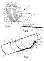
- FIG. 1a shows an example of a connecting part 1 according to the invention essentially from a cut and shaped sheet metal piece 2 and at least a sealing element 3.
- the sheet metal piece 2 is in accordance with the cross-sectional shape of the preformed to connect gutters.
- a semi-cylindrical one Out of shape In the present example, a semi-cylindrical one Out of shape.
- a side margin 2.1 At a side margin 2.1 are e.g. two tensioning devices spaced in the longitudinal direction of the gutter 4, 5 and a tab 6 arranged between them.
- the sheet metal piece 2 On the opposite Side edge 2.2, the sheet metal piece 2 is cylindrical to form a suspension 7 bent outwards. The bent part ends at a certain distance from the outside of the connecting part, so that a longitudinal slot 8 is formed for the suspension 7 becomes.
- the sheet which is typically the same thickness how the gutters to be connected has to be double-layered for increased stability to ensure.
- the sealing element 3 is e.g. one glued to the inside of the sheet metal piece 2 Rubber mat. As can be seen from Fig. 1a, the sealing element 3 covers the inside the sheet metal piece 2 from a large area.
- the end regions 9.1, 9.2 of the connecting part 1 are preferably free of the sealing element 3. You can therefore easily inwards (i.e. to Longitudinal axis of the connecting part 1) to be bent, so that a gradation accordingly approximately the thickness of the sealing element 3 is formed. This gradation covers the finish the gutter connection the sealing element 3 in the axial direction (see. Fig. 2).
- sealing lips 3.1 to 3.5 educated on the surface of the sealing element 3 .
- These are strip-shaped lamellae, which are transverse to the longitudinal axis of the Connecting part 1 run. They extend from one side of the sealing element 3 to the other and can against a mirror symmetry plane (perpendicular to the longitudinal axis) be inclined (cf. Fig. 1 b). In this way it can be achieved can nestle close to the outside of the gutters to be connected.
- the sealing lips 3.1 to 3.5 at regular intervals parallel to each other be arranged.
- a central region of the sealing element 3 is preferably free of Sealing lips.
- the sealing element is with an adhesive layer 26 on the sheet metal piece 2 appropriate.
- Fig. 2 shows a schematic perspective view of the channel connection.
- the Connecting part 1 encloses the two ends that abut one another at the joint 12 Channels 10, 11. Between the sheet metal piece 2 and the outer sides of the channels 10, 11 is the sealing element 3 packed. It prevents water from running out through the joint 12 can.
- the step 13 mentioned above can be clearly seen in FIG forms the end of the connecting part 1.
- the cylindrically bent attachment 7 is formed in one on the grooves 10, 11 Bead 14 attached.
- On the other side of the connection part 1 is through the clamping devices 4, 5 and the tab 6 bent from the outside inwards around the edge of the channel attached.
- the connecting part in the present example is the inside leaving the channels 10, 11 completely free in the water flow area. The flow of the water is not hindered in any way.
- the fasteners (tab 6 etc.) are located themselves on the side where they don't bother.
- the attachment 7 and the bead 14 are matched to one another in such a way that the connecting part when mounting with the suspension 7 in the slot 15 on the underside of the Bead 14 inserted and then pivoted like a door around a hinge, until it lies in the desired position on the outside of the channels.
- the outer radius of the mount 7 is with little play on the inner radius of the Bead 14 adjusted.
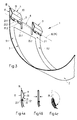
- clamping devices 4, 5 are shown in more detail. They are identical, so that only one of the two is explained below.
- the dash-dotted line 16 indicates where presumably the side edge 24 (see FIG. 2) of the channels runs.
- the sheet metal tab is at an acute angle along an upper edge 18 bent over.
- the upper toggle section 19 closes with the back party 17 Angles of e.g. 20 ° to 45 °.
- the lower toggle section begins at a toggle lever edge 20 21. This is directed towards the back section 17 and forms with the upper toggle section 20 an obtuse angle (in the range of e.g. 90 ° to 135 °).
- a kind of fork is formed at the lower end of the toggle lever section 21. It is a matter of preferably three tabs 22.1, 22.1, 22.3, which are spread out in a fork shape. While the both outer tabs 22.1, 22.3 lie in the area of the lower toggle section 21, the middle tab 22.2 is bent out of the area mentioned. (It runs e.g. roughly in the same direction as the upper toggle section 19.)
- the tab 6 is separated from the tensioning devices 4, 5 by slots 23.1, 23.2.
- the Slots go under line 16, so the tab 6 regardless of what height exactly the side edge 15 of the channels comes to lie, closely around this down can be bent.
- the channels 10, 11 are pre-assembled on the building.
- the channels 10, 11 are advantageously such that they face each other directly without overlap connect.
- the connecting part 1 with its cylindrical side edge 2.2 in the aligned beads 14 of the channels 10, 11 introduced.
- the connecting part 1 (related to the desired end position) turned upside down, so that the suspension 7 is inserted into the bead 14 from below via a longitudinal slot 8 can.
- the connecting part 1 - like a door around a hinge - around the bead 14 pivoted into the desired position on the outside of the channels 10, 11.
- the side edge 24 of the channels 10, 11 can now into the fork (tabs 22.1, 22.2, 22.3) of the clamping devices 4, 5 are introduced. This is shown in Fig. 4a.
- For tensioning of the connecting part 1 is e.g. with a (not shown) commercial flat nose pliers the toggle lever edge 20 pressed against the back.
- the upper and lower toggle sections 19, 21 are now stretched on the back party (Fig. 4b).
- the margin 24 is e.g. has been pressed down a few millimeters, whereby connecting part 1 and Channels 10, 11 are pressed close together.
- the tab 6 is folded around the side edge 15 inwards. Also the upper part of the clamping devices is advantageously bent inwards, as in Fig. 4c shown.
- the kink 25 is advantageously near the fork, but can are also higher up. In this way the tension (clamp connection) between Maintain connection part 1 and channels 10, 11 permanently.
- the connecting part 1 can additionally be riveted to the channels 10, 11.
- the rivets are preferably attached near the side edge, where on the one hand there is no sealing element and where on the other hand they do not interfere with the water flow.
- the force development and the path length of the clamping device can be selected by the The angle and the length of the toggle sections can be dimensioned. Is e.g. the knee angle at the toggle lever edge close to 180 °, the gear ratio between is to be applied Power and resilience very large, but the way very small. Is the knee angle on the other hand, in the range of 90 ° (or below), the clamping device may have an undesirably high friction at the start of the tensioning process.
- a dilation connection can also be created using the same principle.
- the connecting part in this case has a longer (e.g. double) length so that the overlap area (between channel and connecting part) even at low temperatures (i.e. large dilatation joint) is sufficiently large.
- Sealing element are advantageously a plurality of spaced strip-shaped seals intended. Because at low temperatures the joint leads to a larger gap (from several centimeters), whereby the sealing element becomes visible, it can be advantageous in the case of a dilatation connection on the inside of the channel a piece of sheet metal to be installed as protection against UV light.
- the piece of sheet metal can in turn have a cylindrical bead which on the bead 14 Gutters can be hung.
- the opposite end of the (here semi-cylindrical formed) piece of sheet metal can be fixed with the tab 6 or a clamping device.
- the back 17 has z. B. a length of 3 cm, the two toggle sections 19, 21st a length of 1.5 to 2 cm and the tabs 22.1, 22.2, 22.3 have a length of z. B. 3 up to 5 mm.
- the back section 17 and the toggle sections 19, 21 are all of the same width (e.g. 3 cm). This mass is for illustration only. Other dimensions are without further possible.
- the tensioning device should neither be made too small nor too large become. If it is too small, the forces and leverage ratios become unfavorable. Is she too large, it can no longer be operated with a standard tool without having to follow up become.
- the invention is not limited to the embodiment described above.
- the principle according to the invention can be used to connect any open channels be used.
- cylindrical trough shapes are also particularly angular box shapes possible.
- the channels do not have a bulge but only one edge, they can be used instead of the cylindrical one Suspension e.g. hook-shaped inwardly curved tabs may be provided. The tension can then be done against these hook tabs. In the simplest case it is also possible to omit an attachment at all and one side of the connecting part to be riveted directly to the channel ends.
- the sealing element can also be varied.
- a lubricant e.g. silicone oil
- a suitable surface coating can be used.
- rubber can an impregnated compressible foam can also be used.
- the invention creates a channel connection which is fast and without any soldering or welding expertise can be created.
- the inside of the gutter can be free of fittings or fasteners being held. The flow of water is not hindered.
- - unlike a soldering or Welded connection is material-independent. It is suitable e.g. both for copper or stainless steel as well as aluminum.
Landscapes
- Engineering & Computer Science (AREA)
- Architecture (AREA)
- Civil Engineering (AREA)
- Structural Engineering (AREA)
- Roof Covering Using Slabs Or Stiff Sheets (AREA)
- Quick-Acting Or Multi-Walled Pipe Joints (AREA)
- Lift-Guide Devices, And Elevator Ropes And Cables (AREA)
- Handcart (AREA)
- Mechanical Coupling Of Light Guides (AREA)
- Diaphragms For Electromechanical Transducers (AREA)
- Flanged Joints, Insulating Joints, And Other Joints (AREA)
Applications Claiming Priority (2)
| Application Number | Priority Date | Filing Date | Title |
|---|---|---|---|
| CH35899 | 1999-02-26 | ||
| CH35899 | 1999-02-26 |
Publications (2)
| Publication Number | Publication Date |
|---|---|
| EP1031676A1 true EP1031676A1 (fr) | 2000-08-30 |
| EP1031676B1 EP1031676B1 (fr) | 2005-03-23 |
Family
ID=4185204
Family Applications (1)
| Application Number | Title | Priority Date | Filing Date |
|---|---|---|---|
| EP00810098A Expired - Lifetime EP1031676B1 (fr) | 1999-02-26 | 2000-02-04 | Pièce pour le raccordement de deux gouttières |
Country Status (4)
| Country | Link |
|---|---|
| EP (1) | EP1031676B1 (fr) |
| AT (1) | ATE291669T1 (fr) |
| DE (1) | DE50009829D1 (fr) |
| ES (1) | ES2240038T3 (fr) |
Cited By (4)
| Publication number | Priority date | Publication date | Assignee | Title |
|---|---|---|---|---|
| EP1418287A1 (fr) * | 2002-11-05 | 2004-05-12 | Hubertus Willing | Raccord de gouttière |
| FR2850413A1 (fr) | 2003-01-28 | 2004-07-30 | Umicore Nv | Systeme de gouttiere |
| DE202011100611U1 (de) * | 2011-05-12 | 2012-08-14 | Metallwarenfabrik Marktoberdorf Gmbh & Co. Kg | Gummiprofile zur Verbindung von Dachrinnenstücken |
| PL444602A1 (pl) * | 2023-04-26 | 2024-10-28 | Blachotrapez Spółka Z Ograniczoną Odpowiedzialnością | Łącznik rynnowy, profil rynnowy oraz sposób mocowania profili rynnowych z użyciem łącznika |
Families Citing this family (1)
| Publication number | Priority date | Publication date | Assignee | Title |
|---|---|---|---|---|
| DE102005060075A1 (de) * | 2005-12-15 | 2007-06-21 | Metallwarenfabrik Marktoberdorf Gmbh & Co. Kg | Elastisches Dehnungsausgleichselement |
Citations (12)
| Publication number | Priority date | Publication date | Assignee | Title |
|---|---|---|---|---|
| US1693103A (en) * | 1927-04-27 | 1928-11-27 | Frank F Wright | Eaves trough |
| US1780553A (en) * | 1928-09-26 | 1930-11-04 | Phillipp F Flagge | Gutter construction |
| DE6927699U (de) * | 1969-07-09 | 1969-11-20 | Nordplast Kunststoffe Gmbh Fa | Verbindungswinkel fuer dachrinnenabschnitte |
| AU3426568A (en) * | 1969-01-24 | 1970-07-30 | W. E. Cash Proprietary Limited | Solderless joint for guttering and like open channels |
| FR2078433A5 (fr) * | 1970-02-10 | 1971-11-05 | Deutsche Steinzeug | |
| DE2034032A1 (en) * | 1970-01-22 | 1972-01-20 | Braas & Co Gmbh, 6000 Frankfurt | Roof gutter connector - of pvc |
| DE2055011A1 (de) * | 1970-11-09 | 1972-05-10 | Itzehoer Netzfabrik AG, 2210 Itze hoe | Dachrinnenablaufstutzen aus Kunst stoff |
| DE2324247A1 (de) * | 1972-11-20 | 1974-05-22 | Bernd Auer | Rinnenverbinder |
| DE2529497A1 (de) * | 1975-07-02 | 1977-01-13 | Dynamit Nobel Ag | Verbindungsklammer fuer kunststoffdachrinnenabschnitte |
| FR2315591A1 (fr) * | 1975-06-24 | 1977-01-21 | Maier Max | Procede et dispositif de liaison de deux troncons de gouttiere |
| DE3602658A1 (de) * | 1986-01-29 | 1987-08-13 | Franz Zambelli | Rinnenstutzen |
| DE29601767U1 (de) * | 1996-02-02 | 1996-03-21 | Schwall, Theo, 76474 Au | Dachrinnenverbindung |
-
2000
- 2000-02-04 EP EP00810098A patent/EP1031676B1/fr not_active Expired - Lifetime
- 2000-02-04 AT AT00810098T patent/ATE291669T1/de not_active IP Right Cessation
- 2000-02-04 ES ES00810098T patent/ES2240038T3/es not_active Expired - Lifetime
- 2000-02-04 DE DE50009829T patent/DE50009829D1/de not_active Expired - Lifetime
Patent Citations (12)
| Publication number | Priority date | Publication date | Assignee | Title |
|---|---|---|---|---|
| US1693103A (en) * | 1927-04-27 | 1928-11-27 | Frank F Wright | Eaves trough |
| US1780553A (en) * | 1928-09-26 | 1930-11-04 | Phillipp F Flagge | Gutter construction |
| AU3426568A (en) * | 1969-01-24 | 1970-07-30 | W. E. Cash Proprietary Limited | Solderless joint for guttering and like open channels |
| DE6927699U (de) * | 1969-07-09 | 1969-11-20 | Nordplast Kunststoffe Gmbh Fa | Verbindungswinkel fuer dachrinnenabschnitte |
| DE2034032A1 (en) * | 1970-01-22 | 1972-01-20 | Braas & Co Gmbh, 6000 Frankfurt | Roof gutter connector - of pvc |
| FR2078433A5 (fr) * | 1970-02-10 | 1971-11-05 | Deutsche Steinzeug | |
| DE2055011A1 (de) * | 1970-11-09 | 1972-05-10 | Itzehoer Netzfabrik AG, 2210 Itze hoe | Dachrinnenablaufstutzen aus Kunst stoff |
| DE2324247A1 (de) * | 1972-11-20 | 1974-05-22 | Bernd Auer | Rinnenverbinder |
| FR2315591A1 (fr) * | 1975-06-24 | 1977-01-21 | Maier Max | Procede et dispositif de liaison de deux troncons de gouttiere |
| DE2529497A1 (de) * | 1975-07-02 | 1977-01-13 | Dynamit Nobel Ag | Verbindungsklammer fuer kunststoffdachrinnenabschnitte |
| DE3602658A1 (de) * | 1986-01-29 | 1987-08-13 | Franz Zambelli | Rinnenstutzen |
| DE29601767U1 (de) * | 1996-02-02 | 1996-03-21 | Schwall, Theo, 76474 Au | Dachrinnenverbindung |
Cited By (8)
| Publication number | Priority date | Publication date | Assignee | Title |
|---|---|---|---|---|
| EP1418287A1 (fr) * | 2002-11-05 | 2004-05-12 | Hubertus Willing | Raccord de gouttière |
| FR2850413A1 (fr) | 2003-01-28 | 2004-07-30 | Umicore Nv | Systeme de gouttiere |
| DE10303180A1 (de) * | 2003-01-28 | 2004-08-19 | Umicore | Rinnensystem |
| BE1015860A5 (fr) | 2003-01-28 | 2005-10-04 | Umicore Nv | Systeme de gouttiere. |
| DE10303180B4 (de) * | 2003-01-28 | 2006-02-02 | Umicore | Rinnensystem |
| DE202011100611U1 (de) * | 2011-05-12 | 2012-08-14 | Metallwarenfabrik Marktoberdorf Gmbh & Co. Kg | Gummiprofile zur Verbindung von Dachrinnenstücken |
| EP2522791A1 (fr) * | 2011-05-12 | 2012-11-14 | Metallwarenfabrik Marktoberdorf GmbH & Co. KG | Profilé en caoutchouc destiné pour le raccordement de pièces de gouttières |
| PL444602A1 (pl) * | 2023-04-26 | 2024-10-28 | Blachotrapez Spółka Z Ograniczoną Odpowiedzialnością | Łącznik rynnowy, profil rynnowy oraz sposób mocowania profili rynnowych z użyciem łącznika |
Also Published As
| Publication number | Publication date |
|---|---|
| ATE291669T1 (de) | 2005-04-15 |
| EP1031676B1 (fr) | 2005-03-23 |
| DE50009829D1 (de) | 2005-04-28 |
| ES2240038T3 (es) | 2005-10-16 |
Similar Documents
| Publication | Publication Date | Title |
|---|---|---|
| EP1933073B1 (fr) | Raccord de sertissage pour un tuyau | |
| DE19852120C2 (de) | Intumeszierende Brandschutzvorrichtung zum Abschotten von durch Wände oder Decken durchgeführten Rohren | |
| DE10044275A1 (de) | Klemmlasche | |
| DE2744036C3 (de) | Vorrichtung zum Befestigen einer Dacheindeckungsplatte | |
| DE3889424T2 (de) | Dichtungsvorrichtung. | |
| DE4103775A1 (de) | Schaltafel mit an ihren raendern abstehenden randstegen aus flachmaterial | |
| EP1031676A1 (fr) | Pièce pour le raccordement de deux gouttières | |
| DE602005005609T2 (de) | Verbindungshülse für Rohrabzweige | |
| EP0404726A2 (fr) | Dispositif pour la connexion de rails en forme de C, en particulier rails de montage | |
| DE102008055954B4 (de) | Klemmbefestigung von Profilen auf Stehfalz- oder Trapezblechen | |
| DE3213414C2 (fr) | ||
| DE4238725A1 (de) | Kühlergitter | |
| DE60314807T2 (de) | Dichtungsvorrichtung | |
| DE8628124U1 (de) | Faltenbalgen für die Abdeckung von Führungsbahnen u. dgl. an Werkzeugmaschinen u. dgl. | |
| DE69418657T2 (de) | Bauelement | |
| EP0239741A1 (fr) | Tuyau double composé de deux tuyaux de protection liés entre eux en une seule pièce par une nervure | |
| CH628965A5 (de) | Halterung fuer rohre, insbesondere zur verlegung und befestigung von rohren von fussbodenheizungen auf fussboeden. | |
| DE69101528T2 (de) | Befestigungselement für ein Rohr, insbesondere für die Abfuhr von Regenwasser. | |
| DE10213784C1 (de) | Spüle mit Kleber und Justiermittel und Verfahren zum Einbau einer Spüle | |
| DE3301229A1 (de) | Breitbandschelle zum abgedichteten verbinden von glattzylindrischen rohrenden, insbesondere von abwasserrohren mittels eines dichtungselements | |
| EP4174242B1 (fr) | Dispositif d'étanchéité pour étanchéifier le passage entre des éléments de façade d'un élément | |
| DE29904302U1 (de) | Fixierelement für Kantprofile | |
| DE202010007646U1 (de) | Fensterbank | |
| EP3375944A1 (fr) | Conduite de drainage, procédé de fabrication et procédé de montage | |
| DE9001664U1 (de) | Klemmeinrichtung |
Legal Events
| Date | Code | Title | Description |
|---|---|---|---|
| PUAI | Public reference made under article 153(3) epc to a published international application that has entered the european phase |
Free format text: ORIGINAL CODE: 0009012 |
|
| AK | Designated contracting states |
Kind code of ref document: A1 Designated state(s): AT BE CH CY DE DK ES FI FR GB GR IE IT LI LU MC NL PT SE |
|
| AX | Request for extension of the european patent |
Free format text: AL;LT;LV;MK;RO;SI |
|
| 17P | Request for examination filed |
Effective date: 20010221 |
|
| AKX | Designation fees paid |
Free format text: AT BE CH CY DE DK ES FI FR GB GR IE IT LI LU MC NL PT SE |
|
| RAP1 | Party data changed (applicant data changed or rights of an application transferred) |
Owner name: UMICORE STRUB S.A. |
|
| 17Q | First examination report despatched |
Effective date: 20040217 |
|
| GRAP | Despatch of communication of intention to grant a patent |
Free format text: ORIGINAL CODE: EPIDOSNIGR1 |
|
| GRAS | Grant fee paid |
Free format text: ORIGINAL CODE: EPIDOSNIGR3 |
|
| GRAA | (expected) grant |
Free format text: ORIGINAL CODE: 0009210 |
|
| AK | Designated contracting states |
Kind code of ref document: B1 Designated state(s): AT BE CH CY DE DK ES FI FR GB GR IE IT LI LU MC NL PT SE |
|
| PG25 | Lapsed in a contracting state [announced via postgrant information from national office to epo] |
Ref country code: FI Free format text: LAPSE BECAUSE OF FAILURE TO SUBMIT A TRANSLATION OF THE DESCRIPTION OR TO PAY THE FEE WITHIN THE PRESCRIBED TIME-LIMIT Effective date: 20050323 Ref country code: GB Free format text: LAPSE BECAUSE OF FAILURE TO SUBMIT A TRANSLATION OF THE DESCRIPTION OR TO PAY THE FEE WITHIN THE PRESCRIBED TIME-LIMIT Effective date: 20050323 Ref country code: IE Free format text: LAPSE BECAUSE OF FAILURE TO SUBMIT A TRANSLATION OF THE DESCRIPTION OR TO PAY THE FEE WITHIN THE PRESCRIBED TIME-LIMIT Effective date: 20050323 |
|
| REG | Reference to a national code |
Ref country code: GB Ref legal event code: FG4D Free format text: NOT ENGLISH |
|
| REG | Reference to a national code |
Ref country code: CH Ref legal event code: EP |
|
| REG | Reference to a national code |
Ref country code: IE Ref legal event code: FG4D Free format text: GERMAN |
|
| REF | Corresponds to: |
Ref document number: 50009829 Country of ref document: DE Date of ref document: 20050428 Kind code of ref document: P |
|
| PG25 | Lapsed in a contracting state [announced via postgrant information from national office to epo] |
Ref country code: GR Free format text: LAPSE BECAUSE OF FAILURE TO SUBMIT A TRANSLATION OF THE DESCRIPTION OR TO PAY THE FEE WITHIN THE PRESCRIBED TIME-LIMIT Effective date: 20050623 Ref country code: DK Free format text: LAPSE BECAUSE OF FAILURE TO SUBMIT A TRANSLATION OF THE DESCRIPTION OR TO PAY THE FEE WITHIN THE PRESCRIBED TIME-LIMIT Effective date: 20050623 |
|
| PG25 | Lapsed in a contracting state [announced via postgrant information from national office to epo] |
Ref country code: PT Free format text: LAPSE BECAUSE OF FAILURE TO SUBMIT A TRANSLATION OF THE DESCRIPTION OR TO PAY THE FEE WITHIN THE PRESCRIBED TIME-LIMIT Effective date: 20050907 |
|
| REG | Reference to a national code |
Ref country code: ES Ref legal event code: FG2A Ref document number: 2240038 Country of ref document: ES Kind code of ref document: T3 |
|
| GBV | Gb: ep patent (uk) treated as always having been void in accordance with gb section 77(7)/1977 [no translation filed] |
Effective date: 20050323 |
|
| REG | Reference to a national code |
Ref country code: IE Ref legal event code: FD4D |
|
| PLBE | No opposition filed within time limit |
Free format text: ORIGINAL CODE: 0009261 |
|
| STAA | Information on the status of an ep patent application or granted ep patent |
Free format text: STATUS: NO OPPOSITION FILED WITHIN TIME LIMIT |
|
| PG25 | Lapsed in a contracting state [announced via postgrant information from national office to epo] |
Ref country code: AT Free format text: LAPSE BECAUSE OF NON-PAYMENT OF DUE FEES Effective date: 20060204 |
|
| PG25 | Lapsed in a contracting state [announced via postgrant information from national office to epo] |
Ref country code: LU Free format text: LAPSE BECAUSE OF NON-PAYMENT OF DUE FEES Effective date: 20060228 Ref country code: MC Free format text: LAPSE BECAUSE OF NON-PAYMENT OF DUE FEES Effective date: 20060228 |
|
| 26N | No opposition filed |
Effective date: 20051227 |
|
| ET | Fr: translation filed | ||
| PG25 | Lapsed in a contracting state [announced via postgrant information from national office to epo] |
Ref country code: SE Free format text: LAPSE BECAUSE OF FAILURE TO SUBMIT A TRANSLATION OF THE DESCRIPTION OR TO PAY THE FEE WITHIN THE PRESCRIBED TIME-LIMIT Effective date: 20050623 |
|
| PG25 | Lapsed in a contracting state [announced via postgrant information from national office to epo] |
Ref country code: CY Free format text: LAPSE BECAUSE OF FAILURE TO SUBMIT A TRANSLATION OF THE DESCRIPTION OR TO PAY THE FEE WITHIN THE PRESCRIBED TIME-LIMIT Effective date: 20050323 |
|
| PGFP | Annual fee paid to national office [announced via postgrant information from national office to epo] |
Ref country code: ES Payment date: 20100222 Year of fee payment: 11 Ref country code: CH Payment date: 20100223 Year of fee payment: 11 |
|
| PGFP | Annual fee paid to national office [announced via postgrant information from national office to epo] |
Ref country code: IT Payment date: 20100223 Year of fee payment: 11 Ref country code: FR Payment date: 20100226 Year of fee payment: 11 |
|
| PGFP | Annual fee paid to national office [announced via postgrant information from national office to epo] |
Ref country code: DE Payment date: 20100219 Year of fee payment: 11 |
|
| PGFP | Annual fee paid to national office [announced via postgrant information from national office to epo] |
Ref country code: NL Payment date: 20100215 Year of fee payment: 11 |
|
| PGFP | Annual fee paid to national office [announced via postgrant information from national office to epo] |
Ref country code: BE Payment date: 20100401 Year of fee payment: 11 |
|
| BERE | Be: lapsed |
Owner name: S.A. *UMICORE STRUB Effective date: 20110228 |
|
| REG | Reference to a national code |
Ref country code: NL Ref legal event code: V1 Effective date: 20110901 |
|
| REG | Reference to a national code |
Ref country code: CH Ref legal event code: PL |
|
| PG25 | Lapsed in a contracting state [announced via postgrant information from national office to epo] |
Ref country code: LI Free format text: LAPSE BECAUSE OF NON-PAYMENT OF DUE FEES Effective date: 20110228 Ref country code: CH Free format text: LAPSE BECAUSE OF NON-PAYMENT OF DUE FEES Effective date: 20110228 |
|
| REG | Reference to a national code |
Ref country code: FR Ref legal event code: ST Effective date: 20111102 |
|
| PG25 | Lapsed in a contracting state [announced via postgrant information from national office to epo] |
Ref country code: BE Free format text: LAPSE BECAUSE OF NON-PAYMENT OF DUE FEES Effective date: 20110228 |
|
| PG25 | Lapsed in a contracting state [announced via postgrant information from national office to epo] |
Ref country code: NL Free format text: LAPSE BECAUSE OF NON-PAYMENT OF DUE FEES Effective date: 20110901 Ref country code: IT Free format text: LAPSE BECAUSE OF NON-PAYMENT OF DUE FEES Effective date: 20110204 |
|
| REG | Reference to a national code |
Ref country code: DE Ref legal event code: R119 Ref document number: 50009829 Country of ref document: DE Effective date: 20110901 |
|
| PG25 | Lapsed in a contracting state [announced via postgrant information from national office to epo] |
Ref country code: FR Free format text: LAPSE BECAUSE OF NON-PAYMENT OF DUE FEES Effective date: 20110228 |
|
| REG | Reference to a national code |
Ref country code: ES Ref legal event code: FD2A Effective date: 20120411 |
|
| PG25 | Lapsed in a contracting state [announced via postgrant information from national office to epo] |
Ref country code: ES Free format text: LAPSE BECAUSE OF NON-PAYMENT OF DUE FEES Effective date: 20110205 |
|
| PG25 | Lapsed in a contracting state [announced via postgrant information from national office to epo] |
Ref country code: DE Free format text: LAPSE BECAUSE OF NON-PAYMENT OF DUE FEES Effective date: 20110901 |