EP1031685B1 - Barillet de serrure à goupille électromagnétique - Google Patents
Barillet de serrure à goupille électromagnétique Download PDFInfo
- Publication number
- EP1031685B1 EP1031685B1 EP00102384A EP00102384A EP1031685B1 EP 1031685 B1 EP1031685 B1 EP 1031685B1 EP 00102384 A EP00102384 A EP 00102384A EP 00102384 A EP00102384 A EP 00102384A EP 1031685 B1 EP1031685 B1 EP 1031685B1
- Authority
- EP
- European Patent Office
- Prior art keywords
- key
- locking cylinder
- pin
- cylinder according
- switch
- Prior art date
- Legal status (The legal status is an assumption and is not a legal conclusion. Google has not performed a legal analysis and makes no representation as to the accuracy of the status listed.)
- Expired - Lifetime
Links
- 239000004020 conductor Substances 0.000 claims description 12
- 239000003990 capacitor Substances 0.000 claims description 4
- 230000000903 blocking effect Effects 0.000 claims description 2
- 230000001681 protective effect Effects 0.000 claims description 2
- 239000011888 foil Substances 0.000 claims 1
- 238000003780 insertion Methods 0.000 abstract description 2
- 230000037431 insertion Effects 0.000 abstract description 2
- 239000010408 film Substances 0.000 description 4
- 230000004913 activation Effects 0.000 description 2
- 230000013011 mating Effects 0.000 description 2
- 239000013039 cover film Substances 0.000 description 1
- 238000006073 displacement reaction Methods 0.000 description 1
- 230000000694 effects Effects 0.000 description 1
- 230000005611 electricity Effects 0.000 description 1
- 210000000056 organ Anatomy 0.000 description 1
Images



Classifications
-
- G—PHYSICS
- G07—CHECKING-DEVICES
- G07C—TIME OR ATTENDANCE REGISTERS; REGISTERING OR INDICATING THE WORKING OF MACHINES; GENERATING RANDOM NUMBERS; VOTING OR LOTTERY APPARATUS; ARRANGEMENTS, SYSTEMS OR APPARATUS FOR CHECKING NOT PROVIDED FOR ELSEWHERE
- G07C9/00—Individual registration on entry or exit
- G07C9/00174—Electronically operated locks; Circuits therefor; Nonmechanical keys therefor, e.g. passive or active electrical keys or other data carriers without mechanical keys
- G07C9/00944—Details of construction or manufacture
-
- E—FIXED CONSTRUCTIONS
- E05—LOCKS; KEYS; WINDOW OR DOOR FITTINGS; SAFES
- E05B—LOCKS; ACCESSORIES THEREFOR; HANDCUFFS
- E05B47/00—Operating or controlling locks or other fastening devices by electric or magnetic means
- E05B47/06—Controlling mechanically-operated bolts by electro-magnetically-operated detents
- E05B47/0611—Cylinder locks with electromagnetic control
- E05B47/0619—Cylinder locks with electromagnetic control by blocking the rotor
- E05B47/0626—Cylinder locks with electromagnetic control by blocking the rotor radially
- E05B47/063—Cylinder locks with electromagnetic control by blocking the rotor radially with a rectilinearly moveable blocking element
-
- G—PHYSICS
- G07—CHECKING-DEVICES
- G07C—TIME OR ATTENDANCE REGISTERS; REGISTERING OR INDICATING THE WORKING OF MACHINES; GENERATING RANDOM NUMBERS; VOTING OR LOTTERY APPARATUS; ARRANGEMENTS, SYSTEMS OR APPARATUS FOR CHECKING NOT PROVIDED FOR ELSEWHERE
- G07C9/00—Individual registration on entry or exit
- G07C9/00174—Electronically operated locks; Circuits therefor; Nonmechanical keys therefor, e.g. passive or active electrical keys or other data carriers without mechanical keys
- G07C9/00309—Electronically operated locks; Circuits therefor; Nonmechanical keys therefor, e.g. passive or active electrical keys or other data carriers without mechanical keys operated with bidirectional data transmission between data carrier and locks
-
- E—FIXED CONSTRUCTIONS
- E05—LOCKS; KEYS; WINDOW OR DOOR FITTINGS; SAFES
- E05B—LOCKS; ACCESSORIES THEREFOR; HANDCUFFS
- E05B47/00—Operating or controlling locks or other fastening devices by electric or magnetic means
- E05B2047/0048—Circuits, feeding, monitoring
- E05B2047/0057—Feeding
- E05B2047/0062—Feeding by generator
-
- E—FIXED CONSTRUCTIONS
- E05—LOCKS; KEYS; WINDOW OR DOOR FITTINGS; SAFES
- E05B—LOCKS; ACCESSORIES THEREFOR; HANDCUFFS
- E05B47/00—Operating or controlling locks or other fastening devices by electric or magnetic means
- E05B47/0001—Operating or controlling locks or other fastening devices by electric or magnetic means with electric actuators; Constructional features thereof
- E05B47/0002—Operating or controlling locks or other fastening devices by electric or magnetic means with electric actuators; Constructional features thereof with electromagnets
- E05B47/0003—Operating or controlling locks or other fastening devices by electric or magnetic means with electric actuators; Constructional features thereof with electromagnets having a movable core
- E05B47/0004—Operating or controlling locks or other fastening devices by electric or magnetic means with electric actuators; Constructional features thereof with electromagnets having a movable core said core being linearly movable
-
- G—PHYSICS
- G07—CHECKING-DEVICES
- G07C—TIME OR ATTENDANCE REGISTERS; REGISTERING OR INDICATING THE WORKING OF MACHINES; GENERATING RANDOM NUMBERS; VOTING OR LOTTERY APPARATUS; ARRANGEMENTS, SYSTEMS OR APPARATUS FOR CHECKING NOT PROVIDED FOR ELSEWHERE
- G07C9/00—Individual registration on entry or exit
- G07C9/00174—Electronically operated locks; Circuits therefor; Nonmechanical keys therefor, e.g. passive or active electrical keys or other data carriers without mechanical keys
- G07C9/00309—Electronically operated locks; Circuits therefor; Nonmechanical keys therefor, e.g. passive or active electrical keys or other data carriers without mechanical keys operated with bidirectional data transmission between data carrier and locks
- G07C2009/00365—Electronically operated locks; Circuits therefor; Nonmechanical keys therefor, e.g. passive or active electrical keys or other data carriers without mechanical keys operated with bidirectional data transmission between data carrier and locks in combination with a wake-up circuit
- G07C2009/00373—Electronically operated locks; Circuits therefor; Nonmechanical keys therefor, e.g. passive or active electrical keys or other data carriers without mechanical keys operated with bidirectional data transmission between data carrier and locks in combination with a wake-up circuit whereby the wake-up circuit is situated in the lock
-
- G—PHYSICS
- G07—CHECKING-DEVICES
- G07C—TIME OR ATTENDANCE REGISTERS; REGISTERING OR INDICATING THE WORKING OF MACHINES; GENERATING RANDOM NUMBERS; VOTING OR LOTTERY APPARATUS; ARRANGEMENTS, SYSTEMS OR APPARATUS FOR CHECKING NOT PROVIDED FOR ELSEWHERE
- G07C9/00—Individual registration on entry or exit
- G07C9/00174—Electronically operated locks; Circuits therefor; Nonmechanical keys therefor, e.g. passive or active electrical keys or other data carriers without mechanical keys
- G07C2009/00753—Electronically operated locks; Circuits therefor; Nonmechanical keys therefor, e.g. passive or active electrical keys or other data carriers without mechanical keys operated by active electrical keys
- G07C2009/00769—Electronically operated locks; Circuits therefor; Nonmechanical keys therefor, e.g. passive or active electrical keys or other data carriers without mechanical keys operated by active electrical keys with data transmission performed by wireless means
- G07C2009/00777—Electronically operated locks; Circuits therefor; Nonmechanical keys therefor, e.g. passive or active electrical keys or other data carriers without mechanical keys operated by active electrical keys with data transmission performed by wireless means by induction
Definitions
- the invention relates to a lock cylinder with a from an electronic key interrogator electromagnetically releasable locking pin, the Key interrogator by one of the movement a pin tumbler when inserting the key actuated switch is activated.
- the published patent application describes such a shooting cylinder 195 39 235.
- the activation this switch activates the key interrogator.
- the key interrogator has an antenna, this sends an electromagnetic Carrier and information signal from which a transponder in the key box Will be received.
- the transponder then sends in Identification signal returned from the antenna is received and from the key interrogator is evaluated.
- With the correct identifier one of Electromagnet shifted an armature to a locking pin shifted to a release position, so that at in addition correct key profiling the core of the Lock cylinder can be rotated.
- EP 0339102 describes a locking cylinder with an associated key.
- the key carries electronics and a piezo element, which is used for Inserting the key into the lock cylinder is energized to deliver.
- a generic locking cylinder is previously known from US 5,826,450.
- the Lock cylinder has spring-loaded tumbler pins.
- the associated key has a transponder, which is read by a transponder reading device Lock cylinder can be read out.
- the readout device is at Insert the key by actuating a piezoelectric element
- the piezoelectric element can be woken up by the pressure of a Tumbler pin are operated.
- the invention relates to a further development of this armored locking cylinder. You have the task based on the activation of the key interrogation device to improve the key slot.
- the task is solved initially and essentially by the invention specified in claim 1, wherein there is essentially based on the fact that the Switch on counteracting the housing spring of the pin tumbler Pressure sensor is.
- the pressure sensor at which it a piezo element or a film pressure switch can act forms the bottom of the housing pin bore, so that the spring is on this pressure sensor supported. If the key is inserted, the pins shifted out of position, what with a tension of the spring is connected, so that the Pressure that the spring exerts on the pressure sensor at Key slot enlarged and in particular varied. From this pressure increase or from this pressure variation the key interrogator recognizes that a Key is inserted or is inserted and begins with the identification request signal to the To send the key.
- Lock cylinder is based on the content of the OS 195 39 235 referenced.
- the content of this disclosure is fully in the disclosure content this application included.
- the pressure sensor as Film pressure switch is formed and is supported by a carrier strip kept the same time the bottoms of the housing pin holes forms.
- the line connection from the Lock cylinder is preferably carried out by the im Flexible conductors known in the prior art. This runs parallel to the carrier strip. Preferably points the carrier strip has two contacts that are on mating contacts are assigned to the flexible conductor track are.
- the carrier strip can be designed such that he a protective / cover film for the flexible conductor track formed. In particular, on the carrier strip support all or most of the tumbler springs.
- a variant of the invention provides that the generic Lock cylinder equipped with a switch the electrical energy when the switch is actuated supplies.
- This electrical energy can be stored in an energy store be cached and for query identification. In particular, can this energy is temporarily stored in a capacitor his. It is also advantageous if several, in particular all tumblers equipped with energy suppliers are. These energy suppliers can use piezo elements his or other suitable electromechanical organs, which are able to operate mechanically to supply electrical energy.
- the pressure switches can advantageously in the flexible conductor track to get integrated.
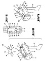
- the lock cylinder 1 has a in a known manner Cylinder core 23 with key channel 24, in which the Shaft of a key 6 can be inserted, in the Key grain a transponder 7 is arranged.
- a multitude of cylinder cores lie one behind the other Core pins 8, which have different lengths and due to different deep cuts in the key shaft can be sorted in such a way that their End face with the joint between cylinder core 23 and cylinder core cavity are aligned so that the cylinder core 23 can be rotated.
- the Lock cylinder 1 a locking pin 11, which in a kind and manner as described in DE 195 39 235, a Cause blocking effect of the rotatability of the cylinder core can if he with his end out of the housing that Crossing joint protrudes in the cylinder core 23.
- the head the locking pin 11 is spring-loaded and is based on a magnetic armature 3, the two stages has. In the position shown in the figures the locking pin 11 is on an elevated level, so that its locking end protrudes into the cylinder core 23.
- the core pins 8 are supported on housing pins 9, these in turn are by means of springs 10, which are on the Support the bottom of the housing pin holes, cushioned.
- the housing pin holes are covered by a carrier strip 13 supported.
- This carrier strip 13 has laterally projecting wings 18 and a pressure switch 12 in the form of a film pressure switch.
- the pressure switch 12 is designed so that when a predetermined is exceeded Limit pressure two arranged on the wings 18 Contacts 16 are interconnected. Will the Pressure switch pressurized with a pressure below of the limit pressure, the two contacts are 16 not linked to each other. The route between the two contacts 16 are therefore suitable as Contact distance to the key interrogation device 4, 5 to supply with electricity.
- the pressure switch is located 12 on the bottom of the second seen from the insertion side Housing pin bore.
- the rounded end portion of the flange portion of the Profile cylinder 1 is formed by a plug-in module 2.
- the plug-in module 2 can in a known manner radial direction in a corresponding recess of the Lock cylinder housing are inserted, including fastening pins 21 in corresponding openings in the housing plunge.
- the plug-in module 2 also has one Screw-through opening 20 through which a fastening screw can protrude into a corresponding Thread of the housing can be screwed.
- On its contact surface to the lock cylinder housing the plug-in module 2 has a recess in which a flexible conductor strip 15 is inserted, which is also a Terminal lug 22 forms.
- the flexible conductor track 15 has 13 congruent wings to the carrier strip, which is connected to mating contacts 17.
- the carrier strip 13 can thus via the flexible conductor track 15 in the opening be inserted that the contacts 16 in electrical Lead connection lie on the contacts 17.
- With a contact tab 19 is a lead connection of the flexible conductor track to the housing
- the plug-in module 2 has one on its end face Antenna.
- the plug-in module 2 is located in the central body the already mentioned electromagnet 4.
- the locking cylinder can by the carrier strip 13 closed openings are donated by the Assembly of the plug-in module 2, these openings are then closed, but can be opened again if necessary become.
- a piezo element is suitable as a pressure switch.
- a film pressure switch is preferably used, that of two electrically spaced apart conductive surfaces that are so deformable or are relocatable, that by loading with a certain pressure in connection with each other can be brought.
- any floor on which a tumbler spring 10 is supported provided with an energy supply switch 12 '.
- additional energy suppliers 12 ' preferably not provided a switching signal leave.
- These energy suppliers 12 ' are only intended deliver electrical energy when the key is inserted.
- the energy-supplying elements 12 'delivered energy is in a not shown Capacitor cached. That energy is used to query the identification signal or has an effect supporting the displacement of the locking pin 11.
- the tumbler pins When the key is inserted, the tumbler pins according to sliding on the notched key narrow side shifted back and forth one or more times.
- the the associated pressure changes generated in the elements 12 and 12 'an energy output that is stored can be.
- the energy suppliers assigned to the various pin tumblers, Piezo elements in particular can be used in terms of circuitry be interconnected. You can be connected in series as well as in series.
Landscapes
- Physics & Mathematics (AREA)
- Engineering & Computer Science (AREA)
- General Physics & Mathematics (AREA)
- Manufacturing & Machinery (AREA)
- Electromagnetism (AREA)
- Computer Networks & Wireless Communication (AREA)
- Lock And Its Accessories (AREA)
- Push-Button Switches (AREA)
- Burglar Alarm Systems (AREA)
- Switches With Compound Operations (AREA)
Claims (11)
- Barillet ou cylindre de serrure (1) avec une broche de blocage (11) libérable d'une façon électromagnétique au moyen d'un dispositif électronique d'interrogation à clé (2 à 5), dans lequel le dispositif d'interrogation à clé (2 à 5) est activé par un détecteur ou capteur de pression (12) actionné par le déplacement d'une gâchette à broches (8 à 10), au moment de l'enfichage de la clé caractérisé en ce que le détecteur de pression est en appui contre les ressorts (10) de boítier de la gâchette à broches.
- Barillet de serrure selon la revendication 1, caractérisé en ce que le détecteur de pression (12) est constitué d'un élément piézoélectrique ou d'un interrupteur à pressage de film.
- Barillet de serrure selon la revendication 2, caractérisé en ce qu'une bande support (13) supportant l'interrupteur à pressage de film (12) constitue les fonds (14) des alésages des broches de boítier.
- Barillet de serrure selon la revendication 3, caractérisé en ce que la bande support (13) s'appuie sur une piste conductrice flexible (15) et qu'elle est en contact avec celle-ci.
- Barillet de serrure selon l'une des revendications 3 ou 4, caractérisé en ce que la bande support (13) comporte des ailes (18) dépassant latéralement et formant des contacts (16) venant électriquement en contact par superposition avec les contacts (17) des ailes correspondantes de la piste conductrice (15)
- Barillet de serrure selon l'une des revendications 4 ou 5, caractérisé en ce que la bande support (13) forme une plaque ou un feuil de revêtement ou de protection pour la piste conductrice flexible (15).
- Barillet ou cylindre de serrure (1) avec une broche de blocage (11), libérable d'une façon électromagnétique par un dispositif électronique d'interrogation à clé (2 à 5), dans lequel le dispositif d'interrogation à clé (2 à 5) est activé par un interrupteur (12) actionné par le déplacement d'une gâchette à broches (8 à 10), au moment de l'enfichage de la clé caractérisé en ce que l'actionnement de l'interrupteur fournit de l'énergie électrique qui est emmagasinée dans un réservoir d'énergie.
- Barillet de serrure selon la revendication 7, caractérisé en ce que le réservoir d'énergie est un condensateur.
- Barillet de serrure selon l'une des revendications 7 ou 8, caractérisé en ce qu'à plusieurs, et particulièrement à toutes les gâchettes à broches (8 à 10), est associé un fournisseur d'énergie qui fournit de l'énergie électrique à l'enfichage de la clé.
- Barillet de serrure selon l'une des revendications 7 à 9, caractérisé en ce que les fournisseurs d'énergie (12') sont des éléments piézoélectriques.
- Barillet de serrure selon l'une des revendications précédentes, caractérisé en ce que le ou les fournisseurs d'énergie, réalisés en particulier comme des interrupteurs à pression, sont intégrés dans la piste conductrice flexible (15).
Applications Claiming Priority (2)
| Application Number | Priority Date | Filing Date | Title |
|---|---|---|---|
| DE19907654 | 1999-02-23 | ||
| DE19907654A DE19907654A1 (de) | 1999-02-23 | 1999-02-23 | Schließzylinder mit elektromagnetisch betätigbarem Sperrstift |
Publications (2)
| Publication Number | Publication Date |
|---|---|
| EP1031685A1 EP1031685A1 (fr) | 2000-08-30 |
| EP1031685B1 true EP1031685B1 (fr) | 2004-05-06 |
Family
ID=7898487
Family Applications (1)
| Application Number | Title | Priority Date | Filing Date |
|---|---|---|---|
| EP00102384A Expired - Lifetime EP1031685B1 (fr) | 1999-02-23 | 2000-02-04 | Barillet de serrure à goupille électromagnétique |
Country Status (3)
| Country | Link |
|---|---|
| EP (1) | EP1031685B1 (fr) |
| AT (1) | ATE266137T1 (fr) |
| DE (2) | DE19907654A1 (fr) |
Cited By (1)
| Publication number | Priority date | Publication date | Assignee | Title |
|---|---|---|---|---|
| CN108343319A (zh) * | 2018-02-27 | 2018-07-31 | 温岭温高教育科技有限公司 | 一种门锁报警防盗装置 |
Families Citing this family (9)
| Publication number | Priority date | Publication date | Assignee | Title |
|---|---|---|---|---|
| DE10217216B4 (de) * | 2002-03-02 | 2005-06-23 | Buga Technologies Gmbh | Betätigungsanordnung für einen Schalter |
| DE10334494A1 (de) * | 2003-07-29 | 2005-02-24 | Aug. Winkhaus Gmbh & Co. Kg | Schließzylinder |
| DE10343109A1 (de) * | 2003-09-18 | 2005-04-21 | Winkhaus Fa August | Schließzylinder |
| US20060226948A1 (en) * | 2005-04-08 | 2006-10-12 | Computerized Security Systems | Door lock with RFID key |
| EP2489815A3 (fr) * | 2005-04-11 | 2012-11-14 | Keso Ag | Dispositif de fermeture |
| FR2901242B1 (fr) * | 2006-05-17 | 2009-02-20 | Airbus Sas | Dispositif de verrouillage d'un element mobile d'un aeronef |
| DE102009005322B4 (de) * | 2009-01-16 | 2013-11-14 | Martin Lehmann Gmbh & Co. Kg | Elektronische Möbelschließeinheit |
| HUP1000360D0 (en) * | 2010-07-12 | 2010-09-28 | Orcifalvi Vilmos | Electronically controlled device for acces ensuring |
| CN103711372B (zh) * | 2013-12-31 | 2017-02-08 | 常州机电职业技术学院 | 弹性钥匙防盗锁头 |
Family Cites Families (7)
| Publication number | Priority date | Publication date | Assignee | Title |
|---|---|---|---|---|
| FR2500520B1 (fr) * | 1981-02-24 | 1988-03-04 | Thomson Csf | Dispositif de commande electromecanique d'une serrure |
| US4912460A (en) * | 1987-07-16 | 1990-03-27 | John Chu | Electrostatically activated gating mechanism |
| EP0339102A1 (fr) * | 1988-04-26 | 1989-11-02 | Herz GmbH | Conversion en énergie électrique d'une énergie mécanique pour le fonctionnement de dispositifs de fermeture électromécaniques |
| DE19539235A1 (de) | 1994-10-25 | 1996-05-02 | Wilka Schliestechnik Gmbh | Schließzylinder mit elektromagnetisch betätigbarem Sperrstift |
| DE19517728C2 (de) * | 1995-05-15 | 1998-12-03 | Keso Gmbh | Schließvorrichtung |
| DE19519789B4 (de) * | 1995-06-02 | 2007-06-21 | Bks Gmbh | Schloß mit Schließzylinder |
| FR2749875B1 (fr) * | 1996-06-17 | 1999-10-08 | Dawalibi Nofal | Dispositif de verrouillage electronique |
-
1999
- 1999-02-23 DE DE19907654A patent/DE19907654A1/de not_active Withdrawn
-
2000
- 2000-02-04 DE DE50006292T patent/DE50006292D1/de not_active Expired - Lifetime
- 2000-02-04 AT AT00102384T patent/ATE266137T1/de not_active IP Right Cessation
- 2000-02-04 EP EP00102384A patent/EP1031685B1/fr not_active Expired - Lifetime
Cited By (1)
| Publication number | Priority date | Publication date | Assignee | Title |
|---|---|---|---|---|
| CN108343319A (zh) * | 2018-02-27 | 2018-07-31 | 温岭温高教育科技有限公司 | 一种门锁报警防盗装置 |
Also Published As
| Publication number | Publication date |
|---|---|
| ATE266137T1 (de) | 2004-05-15 |
| DE50006292D1 (de) | 2004-06-09 |
| EP1031685A1 (fr) | 2000-08-30 |
| DE19907654A1 (de) | 2000-08-24 |
Similar Documents
| Publication | Publication Date | Title |
|---|---|---|
| EP1031685B1 (fr) | Barillet de serrure à goupille électromagnétique | |
| EP0401647B1 (fr) | Système de verrouillage | |
| CH671800A5 (fr) | ||
| DE9202995U1 (de) | Flachschlüssel | |
| EP0922821A2 (fr) | Dispositif d'ouverture de porte | |
| EP0187363B1 (fr) | Clef codée mécaniquement et non-mécaniquement, ainsi que serrure actionnée au moyen de cette clef | |
| EP1380714B1 (fr) | Serrure cylindrique avec dispositif de blocage | |
| EP1996782B1 (fr) | Dispositif pour actionner un élément de fermeture, pourvu d'un générateur électrique | |
| DE2705065A1 (de) | Magnetschalter | |
| CH669426A5 (fr) | ||
| EP2239401B1 (fr) | Cylindre de fermeture rotatif électromécanique | |
| DE19609400C2 (de) | Schließzylinder für ein Schloß | |
| WO1998020220A1 (fr) | Dispositif de fermeture | |
| EP0278359A2 (fr) | Gâche commandée électromagnétiquement | |
| EP2017410B1 (fr) | Mécanisme de blocage électronique | |
| EP0346769A1 (fr) | Dispositif de fermeture comportant une liaison codée pour imprimante | |
| DE4012408C2 (fr) | ||
| DE102005034325A1 (de) | Beschlagsatz | |
| EP2029841A2 (fr) | Dispositif de verrouillage d'une porte coulissante | |
| DE102024125595A1 (de) | Sicherheitseinrichtung | |
| DE19902723C1 (de) | Elektrischer Schalter zur berührungslosen Positionsabfrage eines mechanisch beweglichen ferromagnetischen Teils | |
| DE19629758C2 (de) | Kartenanwesenheitsschalter für Kartenleser | |
| EP3626919A1 (fr) | Poignée de commande pourvue de système de contrôle d'accès | |
| DE19755218A1 (de) | Elektronische Schließvorrichtung | |
| DE3936656A1 (de) | Vorrichtung zum ausloesen eines elektrisch betaetigten schlosses |
Legal Events
| Date | Code | Title | Description |
|---|---|---|---|
| PUAI | Public reference made under article 153(3) epc to a published international application that has entered the european phase |
Free format text: ORIGINAL CODE: 0009012 |
|
| AK | Designated contracting states |
Kind code of ref document: A1 Designated state(s): AT BE CH CY DE DK ES FI FR GB GR IE IT LI LU MC NL PT SE |
|
| AX | Request for extension of the european patent |
Free format text: AL;LT;LV;MK;RO;SI |
|
| 17P | Request for examination filed |
Effective date: 20010109 |
|
| AKX | Designation fees paid |
Free format text: AT BE CH CY DE DK ES FI FR GB GR IE IT LI LU MC NL PT SE |
|
| 17Q | First examination report despatched |
Effective date: 20030505 |
|
| GRAP | Despatch of communication of intention to grant a patent |
Free format text: ORIGINAL CODE: EPIDOSNIGR1 |
|
| GRAS | Grant fee paid |
Free format text: ORIGINAL CODE: EPIDOSNIGR3 |
|
| GRAA | (expected) grant |
Free format text: ORIGINAL CODE: 0009210 |
|
| AK | Designated contracting states |
Kind code of ref document: B1 Designated state(s): AT BE CH CY DE DK ES FI FR GB GR IE IT LI LU MC NL PT SE |
|
| PG25 | Lapsed in a contracting state [announced via postgrant information from national office to epo] |
Ref country code: IT Free format text: LAPSE BECAUSE OF FAILURE TO SUBMIT A TRANSLATION OF THE DESCRIPTION OR TO PAY THE FEE WITHIN THE PRESCRIBED TIME-LIMIT;WARNING: LAPSES OF ITALIAN PATENTS WITH EFFECTIVE DATE BEFORE 2007 MAY HAVE OCCURRED AT ANY TIME BEFORE 2007. THE CORRECT EFFECTIVE DATE MAY BE DIFFERENT FROM THE ONE RECORDED. Effective date: 20040506 Ref country code: FI Free format text: LAPSE BECAUSE OF FAILURE TO SUBMIT A TRANSLATION OF THE DESCRIPTION OR TO PAY THE FEE WITHIN THE PRESCRIBED TIME-LIMIT Effective date: 20040506 Ref country code: FR Free format text: LAPSE BECAUSE OF FAILURE TO SUBMIT A TRANSLATION OF THE DESCRIPTION OR TO PAY THE FEE WITHIN THE PRESCRIBED TIME-LIMIT Effective date: 20040506 Ref country code: GB Free format text: LAPSE BECAUSE OF FAILURE TO SUBMIT A TRANSLATION OF THE DESCRIPTION OR TO PAY THE FEE WITHIN THE PRESCRIBED TIME-LIMIT Effective date: 20040506 Ref country code: IE Free format text: LAPSE BECAUSE OF FAILURE TO SUBMIT A TRANSLATION OF THE DESCRIPTION OR TO PAY THE FEE WITHIN THE PRESCRIBED TIME-LIMIT Effective date: 20040506 Ref country code: NL Free format text: LAPSE BECAUSE OF FAILURE TO SUBMIT A TRANSLATION OF THE DESCRIPTION OR TO PAY THE FEE WITHIN THE PRESCRIBED TIME-LIMIT Effective date: 20040506 |
|
| REG | Reference to a national code |
Ref country code: GB Ref legal event code: FG4D Free format text: NOT ENGLISH |
|
| REG | Reference to a national code |
Ref country code: CH Ref legal event code: EP |
|
| REF | Corresponds to: |
Ref document number: 50006292 Country of ref document: DE Date of ref document: 20040609 Kind code of ref document: P |
|
| REG | Reference to a national code |
Ref country code: IE Ref legal event code: FG4D Free format text: GERMAN |
|
| PG25 | Lapsed in a contracting state [announced via postgrant information from national office to epo] |
Ref country code: SE Free format text: LAPSE BECAUSE OF FAILURE TO SUBMIT A TRANSLATION OF THE DESCRIPTION OR TO PAY THE FEE WITHIN THE PRESCRIBED TIME-LIMIT Effective date: 20040806 Ref country code: GR Free format text: LAPSE BECAUSE OF FAILURE TO SUBMIT A TRANSLATION OF THE DESCRIPTION OR TO PAY THE FEE WITHIN THE PRESCRIBED TIME-LIMIT Effective date: 20040806 Ref country code: DK Free format text: LAPSE BECAUSE OF FAILURE TO SUBMIT A TRANSLATION OF THE DESCRIPTION OR TO PAY THE FEE WITHIN THE PRESCRIBED TIME-LIMIT Effective date: 20040806 |
|
| PG25 | Lapsed in a contracting state [announced via postgrant information from national office to epo] |
Ref country code: ES Free format text: LAPSE BECAUSE OF FAILURE TO SUBMIT A TRANSLATION OF THE DESCRIPTION OR TO PAY THE FEE WITHIN THE PRESCRIBED TIME-LIMIT Effective date: 20040817 |
|
| NLV1 | Nl: lapsed or annulled due to failure to fulfill the requirements of art. 29p and 29m of the patents act | ||
| GBV | Gb: ep patent (uk) treated as always having been void in accordance with gb section 77(7)/1977 [no translation filed] |
Effective date: 20040506 |
|
| REG | Reference to a national code |
Ref country code: IE Ref legal event code: FD4D |
|
| PG25 | Lapsed in a contracting state [announced via postgrant information from national office to epo] |
Ref country code: CY Free format text: LAPSE BECAUSE OF FAILURE TO SUBMIT A TRANSLATION OF THE DESCRIPTION OR TO PAY THE FEE WITHIN THE PRESCRIBED TIME-LIMIT Effective date: 20050204 Ref country code: LU Free format text: LAPSE BECAUSE OF NON-PAYMENT OF DUE FEES Effective date: 20050204 Ref country code: AT Free format text: LAPSE BECAUSE OF NON-PAYMENT OF DUE FEES Effective date: 20050204 |
|
| PG25 | Lapsed in a contracting state [announced via postgrant information from national office to epo] |
Ref country code: MC Free format text: LAPSE BECAUSE OF NON-PAYMENT OF DUE FEES Effective date: 20050228 Ref country code: LI Free format text: LAPSE BECAUSE OF NON-PAYMENT OF DUE FEES Effective date: 20050228 Ref country code: BE Free format text: LAPSE BECAUSE OF NON-PAYMENT OF DUE FEES Effective date: 20050228 Ref country code: CH Free format text: LAPSE BECAUSE OF NON-PAYMENT OF DUE FEES Effective date: 20050228 |
|
| PLBE | No opposition filed within time limit |
Free format text: ORIGINAL CODE: 0009261 |
|
| STAA | Information on the status of an ep patent application or granted ep patent |
Free format text: STATUS: NO OPPOSITION FILED WITHIN TIME LIMIT |
|
| EN | Fr: translation not filed | ||
| 26N | No opposition filed |
Effective date: 20050208 |
|
| BERE | Be: lapsed |
Owner name: *ANKERSLOT B.V. Effective date: 20050228 Owner name: *WILKA SCHLIESSTECHNIK G.M.B.H. Effective date: 20050228 |
|
| REG | Reference to a national code |
Ref country code: CH Ref legal event code: PL |
|
| BERE | Be: lapsed |
Owner name: *ANKERSLOT B.V. Effective date: 20050228 Owner name: *WILKA SCHLIESSTECHNIK G.M.B.H. Effective date: 20050228 |
|
| PG25 | Lapsed in a contracting state [announced via postgrant information from national office to epo] |
Ref country code: PT Free format text: LAPSE BECAUSE OF NON-PAYMENT OF DUE FEES Effective date: 20041006 |
|
| PGFP | Annual fee paid to national office [announced via postgrant information from national office to epo] |
Ref country code: DE Payment date: 20091228 Year of fee payment: 11 |
|
| REG | Reference to a national code |
Ref country code: DE Ref legal event code: R119 Ref document number: 50006292 Country of ref document: DE Effective date: 20110901 |
|
| PG25 | Lapsed in a contracting state [announced via postgrant information from national office to epo] |
Ref country code: DE Free format text: LAPSE BECAUSE OF NON-PAYMENT OF DUE FEES Effective date: 20110901 |