EP1031693B1 - Système de serrage pour une serrure de porte - Google Patents
Système de serrage pour une serrure de porte Download PDFInfo
- Publication number
- EP1031693B1 EP1031693B1 EP00301371A EP00301371A EP1031693B1 EP 1031693 B1 EP1031693 B1 EP 1031693B1 EP 00301371 A EP00301371 A EP 00301371A EP 00301371 A EP00301371 A EP 00301371A EP 1031693 B1 EP1031693 B1 EP 1031693B1
- Authority
- EP
- European Patent Office
- Prior art keywords
- door
- rods
- fixedly mounted
- hook
- lateral
- Prior art date
- Legal status (The legal status is an assumption and is not a legal conclusion. Google has not performed a legal analysis and makes no representation as to the accuracy of the status listed.)
- Expired - Lifetime
Links
Images





Classifications
-
- E—FIXED CONSTRUCTIONS
- E05—LOCKS; KEYS; WINDOW OR DOOR FITTINGS; SAFES
- E05C—BOLTS OR FASTENING DEVICES FOR WINGS, SPECIALLY FOR DOORS OR WINDOWS
- E05C9/00—Arrangements of simultaneously actuated bolts or other securing devices at well-separated positions on the same wing
- E05C9/06—Arrangements of simultaneously actuated bolts or other securing devices at well-separated positions on the same wing with three or more sliding bars
- E05C9/063—Arrangements of simultaneously actuated bolts or other securing devices at well-separated positions on the same wing with three or more sliding bars extending along three or more sides of the wing or frame
-
- E—FIXED CONSTRUCTIONS
- E05—LOCKS; KEYS; WINDOW OR DOOR FITTINGS; SAFES
- E05C—BOLTS OR FASTENING DEVICES FOR WINGS, SPECIALLY FOR DOORS OR WINDOWS
- E05C9/00—Arrangements of simultaneously actuated bolts or other securing devices at well-separated positions on the same wing
- E05C9/10—Actuating mechanisms for bars
- E05C9/12—Actuating mechanisms for bars with rack and pinion mechanism
-
- E—FIXED CONSTRUCTIONS
- E05—LOCKS; KEYS; WINDOW OR DOOR FITTINGS; SAFES
- E05B—LOCKS; ACCESSORIES THEREFOR; HANDCUFFS
- E05B17/00—Accessories in connection with locks
- E05B17/0025—Devices for forcing the wing firmly against its seat or to initiate the opening of the wing
-
- E—FIXED CONSTRUCTIONS
- E05—LOCKS; KEYS; WINDOW OR DOOR FITTINGS; SAFES
- E05C—BOLTS OR FASTENING DEVICES FOR WINGS, SPECIALLY FOR DOORS OR WINDOWS
- E05C9/00—Arrangements of simultaneously actuated bolts or other securing devices at well-separated positions on the same wing
- E05C9/18—Details of fastening means or of fixed retaining means for the ends of bars
- E05C9/1825—Fastening means
- E05C9/1833—Fastening means performing sliding movements
- E05C9/185—Fastening means performing sliding movements parallel with actuating bar
Definitions
- the present invention relates to a lockable door assembly used in boxes and like containers for receiving therein electric instruments, communication instruments and like instruments.
- a turning-point transmission unit is disposed in each of the corner portions of the door; through these turning-point transmission units, a plurality of vertical and lateral rods are connected with each other to form a chain-like assembly to cover the entire peripheral portion of the door; and a plurality of hook members are fixedly mounted on several portions of the vertical and the lateral rods; whereby, when the door is closed, a plurality of catch roller units fixedly mounted on the box body are simultaneously drawn aside by these hook members to compress the packing member between the door and the box body.
- US-A-3,175,873 discloses a panel locking mechanism for console type structures in which a latch bar mounted on a door and movable by means of a handle is provided with a number of hooks, each of which engages with an associated fixed roller when the handle is moved to the closed position.
- a lockable door assembly which is free from any risk that, in a locking operation of a door, a plurality of vertical and lateral rods on which a plurality of hook members are fixedly mounted cause deforming, and also free from any risk that the hook members are subjected to shearing forces, or cause deforming, whereby a packing member is substantially uniformly compressed between the door and a box body.
- the lockable door assembly as set forth in the first aspect of the present invention further comprising:
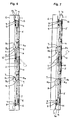
- a right and a left vertical rod 2 are disposed in the right and the left side of a door 1, respectively; an upper and a lower lateral rod 3 are disposed in the upper and the lower side of the door 1, respectively;
- a turning-point transmission unit 4 is fixedly mounted on each of the corner portions of the door 1 and provided with a connecting bar 5 through which the vertical rods 2 and the lateral rods 3 are connected with each other to form a chain-like assembly; and a hook member 8 is fixedly mounted on each of the vertical rods 2 and each of the lateral rods 3.
- the hook member 8 is provided with a hook portion 8a.
- This portion 8a has a cam surface 8c capable of drawing aside a catch roller unit 7 when the door 1 is locked, wherein the catch roller unit 7 is fixedly mounted on a box body 6.
- the hook member 8 is provided with a slot portion 8b which receives therein a guide roller unit 9 fixedly mounted on the door 1.
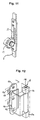
- a pinion gear 11 is mechanically interlocked with a lock handle member 10, and engages with a rack portion 12 which is provided in at least one of the vertical rods 2 or one of the lateral rods 3.
- a packing member 16 is disposed between the box body 6 and the door 1.
- the lockable door assembly as set forth in the first aspect of the present invention further comprises:
- the pinion gear 11 is reversed in rotation by means of the lock handle unit 10, so that the vertical rods 2 and the lateral rods 3 are moved rearward to their unclamping and unlocking positions.
- the catch roller units 7 are disengaged from the hook portions 8a of the hook members 3 of these rods 2, 3.
- the check lever member 19 is rotatably driven by the spring 20 and has its front end portion 19a abut against the periphery of the stop pin 17, which prevents both the vertical rods 2 and the lateral rods 3 from moving in the direction of the arrow (shown in Fig. 14) toward their locking positions, so that the hook members 8 are held in their unlocking (i.e., lock-release) positions.
- the release pin 21 pushes the side surface of the check lever member 19 to rotate the same member 19 about the pivot 18 against a resilient force exerted by the spring 20. Due to this rotational movement of the check lever member 19, the check lever member 19 is disengaged or released from the stop pin 17, which permits the vertical rods 2 and the lateral rods 3 to move forward to their locking positions, and thereby permitting the lock handle unit 10 to be used.
- the left and the right vertical rods 2 are disposed inside the door 1 together with the upper and the lower lateral rods 3.
- the lock handle unit 10 is of a pull-out swinging operation type, and embedded and fixedly mounted in a front surface of the door 1.
- the pinion gear 11 is mechanically interlocked with the locking shaft of the lock handle unit 10, and meshed with the rack portion 12 of the vertical rod 2, as shown in Fig. 11.
- the rack portion 12 is constructed of a series of lateral openings or slots provided at predetermined intervals corresponding to the pitch of the pinion gear 11.
- the slot portion 8b of the hook member 8 assumes an elongated shape extending the length of each of the vertical rods 2 and the lateral rods 3.
- the vertical rods 2, lateral rods 3, turning-point transmission units 4 and the connecting bars 5 are connected in series with each other under tension without permitting any slackness.
- the turning-point transmission units 4 is constructed of a pulley.
- the connecting bar 5 is constructed of an inextensible belt such as strips of metal and the like.
- the lateral rod 3 is slidably received by a guide member 13, while the vertical rod 2 is slidably received by a pair of the guide members 13.
- the guide member 13 is fixedly mounted on an inner surface of the door 1 to stabilize in motion the lateral rods 3 in the vertical direction and the vertical rods 2 in the lateral direction so as to prevent these rods 2, 3 from rattling excessively.
- a flange portion 14 extends around the opening portion of a front wall portion 6a of the box body 6 so as to surround the opening portion. As is clear from Fig. 2, the flange portion 14 is formed so as to protrude forward from a front wall portion 6a of the box body 6.
- the door 1 assumes a flat box-like shape constructed of: a front wall portion 1a which is the same in both shape and size as a front surface outer contoured area of the box body 6; and, a peripheral bent wall portion 1b which is bent four times along four sides of the front wall portion 1a so as to be integrated with the front wall portion 1a.
- the door 1 is supported by a pair of hinge members 15 which are vertically spaced apart from each other along a right edge portion of the box body 6 and fixedly mounted thereon.
- the hinge member 15 is constructed of: a base member 15a fixedly mounted on the box body 6; a support axle 15b vertically slidably mounted in the base member 15a; an arm member 15c fixedly mounted on a front end portion of the support axle 15b; a pivot 15d slidably received in a base end sleeve portion of the arm member 15c; a bearing base 15e for supporting the pivot 15d; and, a compression coil spring 15f mounted on the support axle 15b in an insertion manner between the base member 15a and the front end portion of the arm member 15c.
- the lockable door assembly of the present invention has the above construction, after the door 1 is rotated on the pivot 15d, it is possible for the door 1 to move to its locking position parallel to itself relative to the box body 6 when the catch roller units 7 are drawn aside by the hook members 8.
- the packing member 16 Adhesively applied and fixed to the entire periphery of a front surface of the end portion of the flange portion 14 is the packing member 16 which is made of rubber. It is also possible to provide the packing member 16 in the side of the door 1.
- Each of the box body 6 and the door 1 is constructed of steel plates.
- the spring 20 for biasing the check lever member 19 is constructed of a torsion coil spring.
- the spring 20 has its coiled portion 20a mounted around pin 22. Further, the spring 20 has one 20b of its opposite straight end portions 20b, 20c abut against a spring support portion 24 of the door 1, and the other 20c abut against a spring support pin 23 which is fixedly mounted on the base end portion of the check lever member 19.
- the effect of the present invention is as follows. Namely, as described above, in the lockable door assembly according to the first aspect of the present invention, in a condition in which the vertical rods 2 and the lateral rods 3 forming the chain-like assembly are provided with a plurality of the hook members 8 each of which has its slot portion 8b slidably receive therein the guide roller unit 9 fixedly mounted on the door 1, a plurality of the catch roller units 7 provided in the box body 6 are drawn aside by the hook portions 8a of the hook members 8 while being guided by means of the cam surfaces 8c of the hook members 8 in the door locking operation.
- the hook member 8 is center-balanced by both of: its hook portions 8a engaging with the catch roller unit 7; and its slot portion 8b engaging with the guide roller unit 9, so that shearing forces to which the vertical rods 2 and the lateral rods 3 are subjected are reduced.
- the stop pin 17 is provided in the vertical rod 2 or in the lateral rod 3; and, the front end portion 19a of the check lever member 19 pivotally mounted on the door 1 abuts against the stop pin 17 to prevent both the vertical rods 2 and the lateral rods 3 from moving forward to their locking positions in a condition in which the door 1 is opened, which makes it possible to prevent the catch roller units 7 from hitting and damaging the hook members 8, without fail.
Landscapes
- Engineering & Computer Science (AREA)
- Mechanical Engineering (AREA)
- Specific Sealing Or Ventilating Devices For Doors And Windows (AREA)
- Lock And Its Accessories (AREA)
- Clamps And Clips (AREA)
Claims (2)
- Un ensemble porte verrouillable comprenant :où, lorsque ledit pignon d'engrenage (11) est tourné en service pour déplacer lesdites tiges verticales (2) et les tiges latérales (3), ladite unité de rouleau preneur (7) est attrapée et tirée de côté par ladite partie crochet (8a) dudit élément de crochet (8) de sorte que ledit élément de garniture (16) soit comprimé entre ladite porte (1) et ledit corps de boítier (6),un corps de boítier (6) sur lequel une unité de rouleau preneur (7) est montée fixement ;une porte (1) sur laquelle une unité de rouleau de guidage (9) est montée fixement ;un élément de garniture (16) disposé entre ledit corps de boítier (6) et ladite porte (1) ;une tige verticale de droite et une de gauche (2) disposées dans le côté droit et le côté gauche de ladite porte (1), respectivement ;une tige latérale supérieure et une inférieure (3) disposées dans la face supérieure et la face inférieure de ladite porte (1), respectivement ;un pignon d'engrenage (11) interverrouillé avec un élément de poignée de verrouillage (10), ledit pignon d'engrenage (11) s'engageant avec une partie crémaillère (12) fournie dans au moins une desdites tiges verticales (2) ou une desdites tiges latérales (3) ;une unité de transmission de point de rotation (4) qui est montée fixement sur chacune des parties coins de ladite porte (1) et munie d'une barre de raccordement (5) à travers laquelle lesdites tiges verticales (2) et lesdites tiges latérales (3) sont raccordées les unes avec les autres pour former un ensemble de type chaíne ; etun élément de crochet (8) monté fixement sur chacune desdites tiges verticales (2) et chacune desdites tiges latérales (3), ledit élément de crochet (8) étant muni d'une partie crochet (8a) qui a une surface de came (8a) capable de tirer de côté ladite unité de rouleau preneur (7) lorsque ladite porte (1) est verrouillée ;
caractérisé en ce que chacun desdits éléments de crochet (8) est en plus muni d'une partie fente (8b) qui reçoit ladite unité de rouleau de guidage (9) à l'intérieur. - Un ensemble porte verrouillable selon la revendication 1, comprenant en plus :une goupille d'arrêt (17) fournie sur au moins une desdites tiges verticales (2) ou une desdites tiges latérales (3) ;un élément de levier de contrôle (19) monté de manière pivotante sur ladite porte (1) au moyen d'un pivot (18), ledit élément de levier de contrôle (19) étant incliné de manière rotative par un ressort (20) de façon à avoir sa partie extrémité avant (19a) aboutée contre la périphérie de ladite goupille d'arrêt (17) ; etune goupille de déblocage (21) pour débloquer ledit élément de levier de contrôle (19) de ladite goupille d'arrêt (17) en poussant une surface latérale dudit élément de levier de contrôle (19) à la fin d'une opération de fermeture de ladite porte (1), ladite goupille de déblocage (21) étant montée fixement sur ledit corps de boítier (6).
Applications Claiming Priority (2)
| Application Number | Priority Date | Filing Date | Title |
|---|---|---|---|
| JP11044526A JP2997678B1 (ja) | 1999-02-23 | 1999-02-23 | 扉用締付けロック装置 |
| JP4452699 | 1999-02-23 |
Publications (2)
| Publication Number | Publication Date |
|---|---|
| EP1031693A1 EP1031693A1 (fr) | 2000-08-30 |
| EP1031693B1 true EP1031693B1 (fr) | 2004-07-28 |
Family
ID=12693974
Family Applications (1)
| Application Number | Title | Priority Date | Filing Date |
|---|---|---|---|
| EP00301371A Expired - Lifetime EP1031693B1 (fr) | 1999-02-23 | 2000-02-22 | Système de serrage pour une serrure de porte |
Country Status (4)
| Country | Link |
|---|---|
| EP (1) | EP1031693B1 (fr) |
| JP (1) | JP2997678B1 (fr) |
| AT (1) | ATE272156T1 (fr) |
| DE (1) | DE60012385T2 (fr) |
Cited By (2)
| Publication number | Priority date | Publication date | Assignee | Title |
|---|---|---|---|---|
| US10711646B2 (en) | 2018-07-03 | 2020-07-14 | Rohr, Inc. | Catch assembly for controlling opening of a door |
| RU222236U1 (ru) * | 2023-10-23 | 2023-12-15 | Открытое акционерное общество "Объединенные электротехнические заводы" | Шкаф для электротехнического оборудования |
Families Citing this family (6)
| Publication number | Priority date | Publication date | Assignee | Title |
|---|---|---|---|---|
| FR2873148B1 (fr) * | 2004-06-25 | 2009-04-24 | Ier Sa | Dispositif de verrouillage pour enceinte de fermeture |
| DE102004036612A1 (de) * | 2004-07-28 | 2006-03-23 | Krauss-Maffei Wegmann Gmbh & Co. Kg | Verriegelungsvorrichtung an Lukendeckeln oder Verschlussklappen von Fahrzeugen, insbesondere Kampffahrzeugen |
| CH701704A1 (de) * | 2009-08-28 | 2011-02-28 | Swibox Ag | Druckfester Elektroschrank. |
| JP5388202B2 (ja) * | 2009-11-13 | 2014-01-15 | Necカシオモバイルコミュニケーションズ株式会社 | 電子部品収納装置、及び電子機器 |
| NL1038275C2 (nl) * | 2010-09-30 | 2013-07-01 | Rebeca Hilda Maria Anzola | Waterdichte kozijnen voor deuren en ramen van woningen en gebouwen. |
| GB2488346A (en) * | 2011-02-23 | 2012-08-29 | Renew Pod Ltd | Locking hooks moving along a doors edge in opposite directions simultaneously |
Family Cites Families (5)
| Publication number | Priority date | Publication date | Assignee | Title |
|---|---|---|---|---|
| CH325780A (de) * | 1953-12-10 | 1957-11-30 | Gretsch Unitas Gmbh | Schwing- oder Wendefensterflügel mit Verriegelungsvorrichtung |
| US3175873A (en) * | 1961-06-09 | 1965-03-30 | Fmc Corp | Panel locking mechanism for console type structures |
| DE1281889B (de) * | 1963-04-06 | 1968-10-31 | Ferco Sarl | Zentralverschluss fuer Fenster, Tueren od. dgl. mit einem Zwischenrahmen |
| DE2461887A1 (de) * | 1974-12-30 | 1976-07-08 | Fuhr C Fa | Beschlag fuer fensterfluegel, tueren oder dergleichen |
| DE19547180C2 (de) * | 1995-12-16 | 2001-03-01 | Weru Ag | Fenster- oder Türbeschlag |
-
1999
- 1999-02-23 JP JP11044526A patent/JP2997678B1/ja not_active Expired - Lifetime
-
2000
- 2000-02-22 DE DE60012385T patent/DE60012385T2/de not_active Expired - Lifetime
- 2000-02-22 EP EP00301371A patent/EP1031693B1/fr not_active Expired - Lifetime
- 2000-02-22 AT AT00301371T patent/ATE272156T1/de not_active IP Right Cessation
Cited By (2)
| Publication number | Priority date | Publication date | Assignee | Title |
|---|---|---|---|---|
| US10711646B2 (en) | 2018-07-03 | 2020-07-14 | Rohr, Inc. | Catch assembly for controlling opening of a door |
| RU222236U1 (ru) * | 2023-10-23 | 2023-12-15 | Открытое акционерное общество "Объединенные электротехнические заводы" | Шкаф для электротехнического оборудования |
Also Published As
| Publication number | Publication date |
|---|---|
| JP2000240367A (ja) | 2000-09-05 |
| HK1030251A1 (en) | 2001-04-27 |
| ATE272156T1 (de) | 2004-08-15 |
| EP1031693A1 (fr) | 2000-08-30 |
| DE60012385D1 (de) | 2004-09-02 |
| DE60012385T2 (de) | 2004-12-02 |
| JP2997678B1 (ja) | 2000-01-11 |
Similar Documents
| Publication | Publication Date | Title |
|---|---|---|
| US4256355A (en) | Locking and unlocking device for manually movable wheeled storage rack or the like | |
| CA2306427C (fr) | Poignee de porte interieure pour automobiles | |
| JP3174011B2 (ja) | 鎖錠装置 | |
| JP5544333B2 (ja) | リッド開閉装置 | |
| US6474705B1 (en) | Cab window lock system | |
| US7984942B2 (en) | Flap configuration | |
| DE102010029065A1 (de) | Türkantenschutzeinrichtung | |
| EP1096086A2 (fr) | Serrure de porte, notamment pour tracteurs | |
| EP1031693A1 (fr) | Système de serrage pour une serrure de porte | |
| EP1627758B1 (fr) | Dispositif de verrouillage pour un toit escamotable | |
| EP1132556B1 (fr) | Serrure de porte | |
| US4844524A (en) | Curtainside truck trailer closure assembly | |
| HK1030251B (en) | Door clamping lock system | |
| US4609313A (en) | Box having means for guiding and locking wheeled pallet | |
| JP3564570B2 (ja) | ゲーム機の施錠装置 | |
| EP1006247B1 (fr) | Système de serrure de porte | |
| CA2339025C (fr) | Outil d'alignement de gache | |
| JP3281343B2 (ja) | 扉全周締め込み構造 | |
| AU4587302A (en) | Automotive brake/clutch lock | |
| KR100309845B1 (ko) | 자동차용 백 도어 잠금장치의 직각방향 강도 시험기 | |
| KR100715507B1 (ko) | 도어 잠금장치 | |
| KR20180106239A (ko) | 파지(破紙) 적재함의 덮개장치 | |
| JPS625718B2 (fr) | ||
| KR102768066B1 (ko) | 탑차용 전자키 | |
| JP3582868B2 (ja) | シャッター開閉装置 |
Legal Events
| Date | Code | Title | Description |
|---|---|---|---|
| PUAI | Public reference made under article 153(3) epc to a published international application that has entered the european phase |
Free format text: ORIGINAL CODE: 0009012 |
|
| AK | Designated contracting states |
Kind code of ref document: A1 Designated state(s): AT BE CH CY DE DK ES FI FR GB GR IE IT LI LU MC NL PT SE |
|
| AX | Request for extension of the european patent |
Free format text: AL;LT;LV;MK;RO;SI |
|
| 17P | Request for examination filed |
Effective date: 20000720 |
|
| AKX | Designation fees paid |
Free format text: AT BE CH CY DE DK ES FI FR GB GR IE IT LI LU MC NL PT SE |
|
| 17Q | First examination report despatched |
Effective date: 20030827 |
|
| GRAP | Despatch of communication of intention to grant a patent |
Free format text: ORIGINAL CODE: EPIDOSNIGR1 |
|
| GRAS | Grant fee paid |
Free format text: ORIGINAL CODE: EPIDOSNIGR3 |
|
| GRAA | (expected) grant |
Free format text: ORIGINAL CODE: 0009210 |
|
| AK | Designated contracting states |
Kind code of ref document: B1 Designated state(s): AT BE CH CY DE DK ES FI FR GB GR IE IT LI LU MC NL PT SE |
|
| PG25 | Lapsed in a contracting state [announced via postgrant information from national office to epo] |
Ref country code: FI Free format text: LAPSE BECAUSE OF FAILURE TO SUBMIT A TRANSLATION OF THE DESCRIPTION OR TO PAY THE FEE WITHIN THE PRESCRIBED TIME-LIMIT Effective date: 20040728 Ref country code: CH Free format text: LAPSE BECAUSE OF FAILURE TO SUBMIT A TRANSLATION OF THE DESCRIPTION OR TO PAY THE FEE WITHIN THE PRESCRIBED TIME-LIMIT Effective date: 20040728 Ref country code: AT Free format text: LAPSE BECAUSE OF FAILURE TO SUBMIT A TRANSLATION OF THE DESCRIPTION OR TO PAY THE FEE WITHIN THE PRESCRIBED TIME-LIMIT Effective date: 20040728 Ref country code: LI Free format text: LAPSE BECAUSE OF FAILURE TO SUBMIT A TRANSLATION OF THE DESCRIPTION OR TO PAY THE FEE WITHIN THE PRESCRIBED TIME-LIMIT Effective date: 20040728 Ref country code: NL Free format text: LAPSE BECAUSE OF FAILURE TO SUBMIT A TRANSLATION OF THE DESCRIPTION OR TO PAY THE FEE WITHIN THE PRESCRIBED TIME-LIMIT Effective date: 20040728 |
|
| REG | Reference to a national code |
Ref country code: GB Ref legal event code: FG4D |
|
| RIN1 | Information on inventor provided before grant (corrected) |
Inventor name: SHIROU, SEGAWA Inventor name: HIDEAKI, TAKIMOTO |
|
| REG | Reference to a national code |
Ref country code: CH Ref legal event code: EP |
|
| REG | Reference to a national code |
Ref country code: IE Ref legal event code: FG4D |
|
| REF | Corresponds to: |
Ref document number: 60012385 Country of ref document: DE Date of ref document: 20040902 Kind code of ref document: P |
|
| PG25 | Lapsed in a contracting state [announced via postgrant information from national office to epo] |
Ref country code: GR Free format text: LAPSE BECAUSE OF FAILURE TO SUBMIT A TRANSLATION OF THE DESCRIPTION OR TO PAY THE FEE WITHIN THE PRESCRIBED TIME-LIMIT Effective date: 20041028 Ref country code: SE Free format text: LAPSE BECAUSE OF FAILURE TO SUBMIT A TRANSLATION OF THE DESCRIPTION OR TO PAY THE FEE WITHIN THE PRESCRIBED TIME-LIMIT Effective date: 20041028 Ref country code: DK Free format text: LAPSE BECAUSE OF FAILURE TO SUBMIT A TRANSLATION OF THE DESCRIPTION OR TO PAY THE FEE WITHIN THE PRESCRIBED TIME-LIMIT Effective date: 20041028 |
|
| PG25 | Lapsed in a contracting state [announced via postgrant information from national office to epo] |
Ref country code: ES Free format text: LAPSE BECAUSE OF FAILURE TO SUBMIT A TRANSLATION OF THE DESCRIPTION OR TO PAY THE FEE WITHIN THE PRESCRIBED TIME-LIMIT Effective date: 20041108 |
|
| REG | Reference to a national code |
Ref country code: HK Ref legal event code: GR Ref document number: 1030251 Country of ref document: HK |
|
| NLV1 | Nl: lapsed or annulled due to failure to fulfill the requirements of art. 29p and 29m of the patents act | ||
| REG | Reference to a national code |
Ref country code: CH Ref legal event code: PL |
|
| PG25 | Lapsed in a contracting state [announced via postgrant information from national office to epo] |
Ref country code: CY Free format text: LAPSE BECAUSE OF FAILURE TO SUBMIT A TRANSLATION OF THE DESCRIPTION OR TO PAY THE FEE WITHIN THE PRESCRIBED TIME-LIMIT Effective date: 20050222 |
|
| ET | Fr: translation filed | ||
| PG25 | Lapsed in a contracting state [announced via postgrant information from national office to epo] |
Ref country code: MC Free format text: LAPSE BECAUSE OF NON-PAYMENT OF DUE FEES Effective date: 20050228 |
|
| PLBE | No opposition filed within time limit |
Free format text: ORIGINAL CODE: 0009261 |
|
| STAA | Information on the status of an ep patent application or granted ep patent |
Free format text: STATUS: NO OPPOSITION FILED WITHIN TIME LIMIT |
|
| 26N | No opposition filed |
Effective date: 20050429 |
|
| PG25 | Lapsed in a contracting state [announced via postgrant information from national office to epo] |
Ref country code: PT Free format text: LAPSE BECAUSE OF NON-PAYMENT OF DUE FEES Effective date: 20041228 |
|
| PGFP | Annual fee paid to national office [announced via postgrant information from national office to epo] |
Ref country code: LU Payment date: 20130301 Year of fee payment: 14 Ref country code: IE Payment date: 20130212 Year of fee payment: 14 |
|
| PGFP | Annual fee paid to national office [announced via postgrant information from national office to epo] |
Ref country code: BE Payment date: 20130212 Year of fee payment: 14 |
|
| BERE | Be: lapsed |
Owner name: *TAKIGEN MFG CO. LTD Effective date: 20140228 |
|
| PG25 | Lapsed in a contracting state [announced via postgrant information from national office to epo] |
Ref country code: LU Free format text: LAPSE BECAUSE OF NON-PAYMENT OF DUE FEES Effective date: 20140222 |
|
| REG | Reference to a national code |
Ref country code: IE Ref legal event code: MM4A |
|
| PG25 | Lapsed in a contracting state [announced via postgrant information from national office to epo] |
Ref country code: BE Free format text: LAPSE BECAUSE OF NON-PAYMENT OF DUE FEES Effective date: 20140228 Ref country code: IE Free format text: LAPSE BECAUSE OF NON-PAYMENT OF DUE FEES Effective date: 20140222 |
|
| REG | Reference to a national code |
Ref country code: FR Ref legal event code: PLFP Year of fee payment: 16 |
|
| REG | Reference to a national code |
Ref country code: FR Ref legal event code: PLFP Year of fee payment: 17 |
|
| REG | Reference to a national code |
Ref country code: FR Ref legal event code: PLFP Year of fee payment: 18 |
|
| PGFP | Annual fee paid to national office [announced via postgrant information from national office to epo] |
Ref country code: FR Payment date: 20170112 Year of fee payment: 18 Ref country code: DE Payment date: 20170214 Year of fee payment: 18 |
|
| PGFP | Annual fee paid to national office [announced via postgrant information from national office to epo] |
Ref country code: GB Payment date: 20170222 Year of fee payment: 18 |
|
| PGFP | Annual fee paid to national office [announced via postgrant information from national office to epo] |
Ref country code: IT Payment date: 20170221 Year of fee payment: 18 |
|
| REG | Reference to a national code |
Ref country code: DE Ref legal event code: R119 Ref document number: 60012385 Country of ref document: DE |
|
| GBPC | Gb: european patent ceased through non-payment of renewal fee |
Effective date: 20180222 |
|
| REG | Reference to a national code |
Ref country code: FR Ref legal event code: ST Effective date: 20181031 |
|
| PG25 | Lapsed in a contracting state [announced via postgrant information from national office to epo] |
Ref country code: DE Free format text: LAPSE BECAUSE OF NON-PAYMENT OF DUE FEES Effective date: 20180901 |
|
| PG25 | Lapsed in a contracting state [announced via postgrant information from national office to epo] |
Ref country code: IT Free format text: LAPSE BECAUSE OF NON-PAYMENT OF DUE FEES Effective date: 20180222 Ref country code: FR Free format text: LAPSE BECAUSE OF NON-PAYMENT OF DUE FEES Effective date: 20180228 Ref country code: GB Free format text: LAPSE BECAUSE OF NON-PAYMENT OF DUE FEES Effective date: 20180222 |