EP1031703A2 - Dispositifs de commande d'aubes directrices - Google Patents
Dispositifs de commande d'aubes directrices Download PDFInfo
- Publication number
- EP1031703A2 EP1031703A2 EP00300999A EP00300999A EP1031703A2 EP 1031703 A2 EP1031703 A2 EP 1031703A2 EP 00300999 A EP00300999 A EP 00300999A EP 00300999 A EP00300999 A EP 00300999A EP 1031703 A2 EP1031703 A2 EP 1031703A2
- Authority
- EP
- European Patent Office
- Prior art keywords
- pin
- aperture
- projection
- arrangement according
- operating arrangement
- Prior art date
- Legal status (The legal status is an assumption and is not a legal conclusion. Google has not performed a legal analysis and makes no representation as to the accuracy of the status listed.)
- Withdrawn
Links
- 230000007423 decrease Effects 0.000 claims description 4
- 230000000712 assembly Effects 0.000 description 3
- 238000000429 assembly Methods 0.000 description 3
- 238000005266 casting Methods 0.000 description 1
- 230000003247 decreasing effect Effects 0.000 description 1
- 230000001419 dependent effect Effects 0.000 description 1
- 230000000694 effects Effects 0.000 description 1
- 238000012986 modification Methods 0.000 description 1
- 230000004048 modification Effects 0.000 description 1
- 238000005096 rolling process Methods 0.000 description 1
Images


Classifications
-
- F—MECHANICAL ENGINEERING; LIGHTING; HEATING; WEAPONS; BLASTING
- F01—MACHINES OR ENGINES IN GENERAL; ENGINE PLANTS IN GENERAL; STEAM ENGINES
- F01D—NON-POSITIVE DISPLACEMENT MACHINES OR ENGINES, e.g. STEAM TURBINES
- F01D17/00—Regulating or controlling by varying flow
- F01D17/10—Final actuators
- F01D17/12—Final actuators arranged in stator parts
- F01D17/14—Final actuators arranged in stator parts varying effective cross-sectional area of nozzles or guide conduits
- F01D17/16—Final actuators arranged in stator parts varying effective cross-sectional area of nozzles or guide conduits by means of nozzle vanes
- F01D17/162—Final actuators arranged in stator parts varying effective cross-sectional area of nozzles or guide conduits by means of nozzle vanes for axial flow, i.e. the vanes turning around axes which are essentially perpendicular to the rotor centre line
Definitions
- This invention relates to operating arrangements for stator vanes. More particularly, the invention relates to operating arrangements for stator vanes in gas turbine engines. The invention also relates to operating levers for stator vanes and to control members for controlling such operating levers.
- Gas turbine engines generally comprise an arrangement of compressors, fans and turbines. These may be provided with adjustable stator vanes alternating with rotating blades. The orientation of the stator vanes can be adjusted by pivotally rotating each of them about its longitudinal axis to vary the flow of air through the engine.
- the movement of the variable stator vanes is controlled by a number of levers, each attached by a pin to a unison ring extending around the stator. As the unison ring rotates, it moves the levers to adjust the vanes in unison. On rotation of the ring, the apertures in which the pins are received remain aligned with the radiis of the ring.
- the pins however, are fixed and do not maintain their alignment with the radiis of the ring on such rotation. This causes flexing in the lever, which can lead to failure of the pins or levers.
- an operating arrangement for an adjustable stator vane in a gas turbine engine comprising a control member defining an aperture, and an operating lever having a first end region to be secured to the stator vane, and a second end region having a pin extending therefrom to be received in said aperture in the control member, wherein the pin is movable longitudinally relative to the aperture, and a laterally extending projection is provided on one of the pin and the aperture to engage the other of the pin and the wall of the aperture, such that relative pivotal and longitudinal movement of the longitudinal axes of the pin and of the aperture is permitted on movement of the control member to move the operating lever.
- the projection is provided on the pin. In an another embodiment, the projection is provided on the wall of the aperture or recess.
- an operating lever for use in an operating arrangement for an adjustable stator vane in a gas turbine engine, said lever comprising a first end region to be secured to the stator vane and a second end region having a pin extending therefrom to be received in an aperture defined in a control member, the pin and the aperture being movable longitudinally relative to each other, and a laterally extending projection being provided on the pin to engage the wall of the aperture, such that relative pivotal and longitudinal movement of the longitudinal axes of the pin and of the aperture is permitted on movement of the control member to move the operating lever.
- the projection may extend at least partially around and, preferably, substantially wholly around, the pin.
- the pin comprises a first portion comprising a shank of the pin, said first portion extending from the second end region of the operating lever, and said pin further including a second portion extending substantially co-axially from the first portion, said projection extending laterally from the second portion.
- Both said first and second, portions are preferably conveniently of substantially circular cross-section.
- the projection may extend longitudinally of the pin, and may extend throughout the length of the second portion. Desirably, the projection tapers such that the cross-section of the second portion increases to a maximum, and then decreases from said maximum.
- the taper may be arcuate. Desirably, the projection is substantially barrel shaped.
- a control member for use in an operating arrangement for a stator vane in a gas turbine engine, said control member defining an aperture adapted to receive a pin of an operating lever secured to the stator vane, the pin and the aperture being movable longitudinally relative to each other, wherein a laterally extending projection is provided on the wall of the aperture to engage the pin such that relative pivotal movement of the longitudinal axes of the pin and the aperture is permitted on movement of the control member to move the operating lever.
- the projection may extend substantially wholly around the aperture, and may extend longitudinally of the recess.
- the projection tapers such that the cross-section of the aperture decreases to a minimum, and then increases from said minimum.
- the taper may be arcuate.
- an insert may be fitted into the aperture in the control member to receive the pin.
- the insert may be a low friction bush.
- the expression wall of the aperture should be interpreted to cover both the wall of such an insert and the wall of the aperture itself.
- control member is in the form of a unison ring having a plurality of apertures.
- the unison ring may extend at least partially, and preferably substantially wholly around the engine.
- the arrangement includes a plurality of operating levers, each adapted to be secured to a respective stator vane and the pin of each lever is received in a respective one of the recesses or apertures in the unison ring.
- stator vane has an axis and the pin extends in a direction substantially parallel to the axis of the stator vane so that the longitudinal axis of the pin is substantially parallel to the axis of the stator vane.
- the stator vane preferably adjustably pivoting about said axis of the stator vane.
- the invention also provides an axial flow compressor incorporating an operating arrangement as described above and a gas turbine engine incorporating such a compressor.
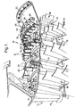
- FIG. 1 there is shown a sectional view of an axial flow compressor 10 of a gas turbine engine which comprises a plurality of stator vane assemblies 12, wherein each assembly 12 comprises a plurality of stator vanes 14 arranged in an annular fashion about the axis of the compressor 10. Alternating with the stator vane assemblies 12 are a plurality of rotor assemblies 16.
- Each stator vane 14 comprises a spindle 18 extending radially of the compressor 10.
- Each spindle 18 is rotatably mounted in a respective bearing 20 formed on the casing 22 of the compressor 10, and each stator vane 14 can pivot about its respective spindle 18 about a central axis C of the vane 14.
- each stator vane 14 is controlled by an operating lever 24 which is fastened to the spindle by appropriate fastening means 26 at a first end region 28 of the operating lever 24.
- a pin 34 extends from the opposite second end region 36 of the operating lever 24 (see Figs. 2 and 3). The pin 34 extends from the operating lever 24 in a direction substantially parallel to the axis C of the stator vane 14 and spindle 18.
- An annular control member in the form of a unison ring 30 extends circumferentially around the casing 22 of the compressor 10. Referring to Fig. 2, the unison ring 30 and the mounting thereon of one of the levers 24 is shown. In this figure, only half of the unison ring 30 is shown for clarity.
- Each unison ring 30 is of substantially square cross section, and defines a plurality of substantially equi-spaced apertures 32 extending therethrough.
- Each pin 34 has a first cylindrical shank portion 38 secured to and extending from the second end region 36 of the lever 24.
- a second portion 40 extends from the first portion 38 and is provided with a laterally extending projection 41.
- the projection 41 is of circular cross section and has an arcuate longitudinal profile. The circular cross-section of the pin 34 is tapered, increasing at a region 42 to a maximum at a central region of the second portion 40 and then decreasing from the maximum at a second region 44.
- the projection 41 is substantially barrel shaped.
- the projection 41 extends laterally beyond the cylindrical portion 38 at shoulder 43.
- the second portion 40 may be formed integrally with the cylindrical portion 38, for example by casting.
- the projection 41 has been shown such that it is widest at the central region 46, it will be appreciated that the position of the widest region of the projection 41 will be dependent on various factors including the overall geometry of the arrangement and will vary for different situations.
- each operating lever 24 is received in a respective one of the apertures 32 in the unison ring 30.
- the unison ring 30 is rotated about its central axis to move each of the operating levers 24 rotationally therewith.
- the rotational movement of each operating lever causes consequential pivotal movement of its respective stator vane 14.
- FIGs. 5A to 5C there is shown three positions of one pin 38 in relation to the aperture 32 of the unison ring 30 in which it is received.
- the aperture 32 is defined by a cylindrical wall 50.
- Fig. 5A there is shown the central or null position of the unison ring 30 and operating lever 24, whereas Figs. 5B and 5C show respectively the extreme positions either side of the central or null position.
- Figs. 5A to 5C the longitudinal central axis of the aperture 32 is shown by the solid line designated A, and the longitudinal central axis of the pin 34 is shown by the dashed line designated B.
- the axes A and B are coincident and, therefore, only one of the axes, i.e. A is designated. In this position, both diametrically opposite regions 50A, 50B of the wall 50 of the aperture 32 engage the centre region 46 of the projection 41.
- the aperture will take up the position shown in Fig. 5B.
- the axis A of the aperture remains radially oriented with respect to the centre of the unison ring 30.
- the longitudinal axis B of the pin 34 remains parallel to the axis of the pin 34 in the central position as shown in Fig. 5A.
- the two axes A and B are thus angled to each other. This is represented by the angle ⁇ in Fig. 5B.
- first region 50A of the wall 50 engages the corresponding section of the first region 42 of the pin 34
- diametrically opposite second region 50B of the wall 50 i.e. the left hand side
- the central axis A of the aperture 32 extends radially of the unison ring 30, whereas the central axis B of the pin 34 remains parallel to the central axis B shown in Fig. 5A, the two axes A and B being angled to each other by an angle ⁇ as shown in Fig. 5C.
- the first region 50A of the wall 50 engages the second region 44 of the pin 34 and the second region 50B engages the first region 42 of the pin 34.
- the movement of the aperture 32 to the position shown in Fig. 5C will cause a slight longitudinal movement of the pin 34 relative to the aperture 32.
- the effect is of relative rotational or rolling movement of the wall 50 of the aperture 32 with respect to the projection 41 of the pin 34.
- FIG. 6 there is shown an alternative arrangement comprising a pin 134 which is cylindrical in configuration and omits the projection 41 of the pin 34 described above.
- the arrangement also comprises an aperture 132 in the unison ring 30, in which the side wall of the aperture 132 is provided with an inwardly directed lateral projection 141 which is of an arcuate or barrelled configuration.
- the projection 141 on the wall 150 engages the cylindrical pin 134.
Landscapes
- Engineering & Computer Science (AREA)
- Mechanical Engineering (AREA)
- General Engineering & Computer Science (AREA)
- Control Of Turbines (AREA)
- Structures Of Non-Positive Displacement Pumps (AREA)
- Turbine Rotor Nozzle Sealing (AREA)
- Supercharger (AREA)
Applications Claiming Priority (2)
| Application Number | Priority Date | Filing Date | Title |
|---|---|---|---|
| GBGB9904032.1A GB9904032D0 (en) | 1999-02-23 | 1999-02-23 | Operating arrangements for stator vanes |
| GB9904032 | 1999-02-23 |
Publications (2)
| Publication Number | Publication Date |
|---|---|
| EP1031703A2 true EP1031703A2 (fr) | 2000-08-30 |
| EP1031703A3 EP1031703A3 (fr) | 2000-09-13 |
Family
ID=10848263
Family Applications (1)
| Application Number | Title | Priority Date | Filing Date |
|---|---|---|---|
| EP00300999A Withdrawn EP1031703A3 (fr) | 1999-02-23 | 2000-02-09 | Dispositifs de commande d'aubes directrices |
Country Status (2)
| Country | Link |
|---|---|
| EP (1) | EP1031703A3 (fr) |
| GB (1) | GB9904032D0 (fr) |
Cited By (8)
| Publication number | Priority date | Publication date | Assignee | Title |
|---|---|---|---|---|
| EP1256698A3 (fr) * | 2001-05-11 | 2004-03-10 | AVIO S.p.A. | Turbine axiale avec stator à géométrie variable |
| EP1867877A1 (fr) * | 2006-06-16 | 2007-12-19 | Ansaldo Energia S.P.A. | Compresseur d'une turbine à gaz |
| EP2031254A1 (fr) * | 2007-08-30 | 2009-03-04 | Snecma | Aubage à calage variable de turbomachine |
| US20110277587A1 (en) * | 2007-08-03 | 2011-11-17 | Dugas Patrick J | Variable inertia flywheel |
| US20150204418A1 (en) * | 2007-08-03 | 2015-07-23 | Patrick J. Dugas | Variable inertia flywheel |
| EP3865675A1 (fr) * | 2020-02-13 | 2021-08-18 | Honeywell International Inc. | Système d'aube variable pour une turbomachine avec un levier doté d'une ouverture de réception conique pour un tennon d'un anneau de commande |
| CN114991881A (zh) * | 2021-03-01 | 2022-09-02 | 中国航发商用航空发动机有限责任公司 | 静叶调节机构及包含其的发动机 |
| EP4177444A1 (fr) * | 2021-11-08 | 2023-05-10 | MTU Aero Engines AG | Aube directrice à calage variable avec section de palier radialement intérieure convexe pour turbine à gaz, en particulier turbine à gaz d'avion |
Family Cites Families (4)
| Publication number | Priority date | Publication date | Assignee | Title |
|---|---|---|---|---|
| CH661772A5 (de) * | 1983-05-31 | 1987-08-14 | Escher Wyss Ag | Axiale turbomaschine. |
| DE3711224A1 (de) * | 1987-04-03 | 1988-10-13 | Gutehoffnungshuette Man | Verstelleinrichtung fuer die leitschaufeln einer axialstroemungsmaschine |
| DE69010519T2 (de) * | 1989-02-02 | 1994-11-10 | Hitachi Ltd | Leitschaufel-Regler. |
| DE4102188C2 (de) * | 1991-01-25 | 1994-09-22 | Mtu Muenchen Gmbh | Leitschaufel-Verstelleinrichtung einer Turbine eines Gasturbinentriebwerks |
-
1999
- 1999-02-23 GB GBGB9904032.1A patent/GB9904032D0/en not_active Ceased
-
2000
- 2000-02-09 EP EP00300999A patent/EP1031703A3/fr not_active Withdrawn
Cited By (15)
| Publication number | Priority date | Publication date | Assignee | Title |
|---|---|---|---|---|
| EP1256698A3 (fr) * | 2001-05-11 | 2004-03-10 | AVIO S.p.A. | Turbine axiale avec stator à géométrie variable |
| US6860717B2 (en) | 2001-05-11 | 2005-03-01 | Avio S.P.A. | Axial turbine for aeronautical applications |
| EP1867877A1 (fr) * | 2006-06-16 | 2007-12-19 | Ansaldo Energia S.P.A. | Compresseur d'une turbine à gaz |
| WO2007144430A1 (fr) * | 2006-06-16 | 2007-12-21 | Ansaldo Energia S.P.A. | Compresseur de turbine à gaz |
| US8075253B2 (en) | 2006-06-16 | 2011-12-13 | Ansaldo Energia S.P.A. | Gas turbine compressor |
| US20110277587A1 (en) * | 2007-08-03 | 2011-11-17 | Dugas Patrick J | Variable inertia flywheel |
| US20150204418A1 (en) * | 2007-08-03 | 2015-07-23 | Patrick J. Dugas | Variable inertia flywheel |
| FR2920469A1 (fr) * | 2007-08-30 | 2009-03-06 | Snecma Sa | Aube a calage variable de turbomachine |
| EP2031254A1 (fr) * | 2007-08-30 | 2009-03-04 | Snecma | Aubage à calage variable de turbomachine |
| US8206090B2 (en) | 2007-08-30 | 2012-06-26 | Snecma | Variable-pitch vane of a turbomachine |
| EP3865675A1 (fr) * | 2020-02-13 | 2021-08-18 | Honeywell International Inc. | Système d'aube variable pour une turbomachine avec un levier doté d'une ouverture de réception conique pour un tennon d'un anneau de commande |
| CN114991881A (zh) * | 2021-03-01 | 2022-09-02 | 中国航发商用航空发动机有限责任公司 | 静叶调节机构及包含其的发动机 |
| CN114991881B (zh) * | 2021-03-01 | 2023-09-19 | 中国航发商用航空发动机有限责任公司 | 静叶调节机构及包含其的发动机 |
| EP4177444A1 (fr) * | 2021-11-08 | 2023-05-10 | MTU Aero Engines AG | Aube directrice à calage variable avec section de palier radialement intérieure convexe pour turbine à gaz, en particulier turbine à gaz d'avion |
| US11892012B2 (en) | 2021-11-08 | 2024-02-06 | MTU Aero Engines AG | Adjustable guide vane with convexly shaped, radially inner storage section for a gas turbine, in particular an aircraft gas turbine |
Also Published As
| Publication number | Publication date |
|---|---|
| GB9904032D0 (en) | 1999-04-14 |
| EP1031703A3 (fr) | 2000-09-13 |
Similar Documents
| Publication | Publication Date | Title |
|---|---|---|
| EP2581560B1 (fr) | Aube directrice d'entrée de compresseur haute pression inclinée | |
| EP4008884B1 (fr) | Ensemble d'aubes directrices variables pour un moteur à turbine à gaz et moteur à turbine à gaz | |
| EP1967718B1 (fr) | Virole pour turbine à gaz ayant des aubes de guidage à calage variable | |
| US8123471B2 (en) | Variable stator vane contoured button | |
| US6682299B2 (en) | Variable stator vane support arrangement | |
| US8376693B2 (en) | Variable vane assembly | |
| EP1980721B2 (fr) | Ensemble d'aube de stator orientable pour moteur de turbine | |
| US20100260591A1 (en) | Spanwise split variable guide vane and related method | |
| US4950129A (en) | Variable inlet guide vanes for an axial flow compressor | |
| US10837307B2 (en) | System of variable stator vanes for a turbine engine | |
| US8376692B2 (en) | Turbo compressor in an axial type of construction | |
| RU2564158C2 (ru) | Способ регулирования расхода воздуха в центробежном компрессоре турбомашины и диффузор для его осуществления | |
| US7104754B2 (en) | Variable vane arrangement for a turbomachine | |
| JP4398694B2 (ja) | トルクチューブ軸受組立体 | |
| US6984105B2 (en) | Control of variable stator vanes in a gas turbine engine | |
| US20180223868A1 (en) | Turbine Engine Compressor with Variable-Pitch Vanes | |
| EP1031703A2 (fr) | Dispositifs de commande d'aubes directrices | |
| CN105874171B (zh) | 飞机涡轮螺旋桨或涡轮风扇的涡轮发动机压缩机 | |
| US10648359B2 (en) | System for controlling variable-setting blades for a turbine engine | |
| EP4296523A1 (fr) | Conception de compresseur/rotor soufflant caréné à géométrie variable | |
| EP1481151B1 (fr) | Conception amelioree d'aube utilisee dans des turbocompresseurs a geometrie variable | |
| EP1647673B1 (fr) | Obturateur à disque rotatif | |
| JP2018178835A (ja) | 可変静翼 | |
| GB2531922A (en) | System for controlling variable-pitch vanes for a turbine engine | |
| GB2399865A (en) | Improvements in or relating to control of variable stator vanes in a gas turbine engine |
Legal Events
| Date | Code | Title | Description |
|---|---|---|---|
| PUAI | Public reference made under article 153(3) epc to a published international application that has entered the european phase |
Free format text: ORIGINAL CODE: 0009012 |
|
| PUAL | Search report despatched |
Free format text: ORIGINAL CODE: 0009013 |
|
| AK | Designated contracting states |
Kind code of ref document: A2 Designated state(s): DE FR GB |
|
| AX | Request for extension of the european patent |
Free format text: AL;LT;LV;MK;RO;SI |
|
| AK | Designated contracting states |
Kind code of ref document: A3 Designated state(s): AT BE CH CY DE DK ES FI FR GB GR IE IT LI LU MC NL PT SE |
|
| AX | Request for extension of the european patent |
Free format text: AL;LT;LV;MK;RO;SI |
|
| 17P | Request for examination filed |
Effective date: 20000814 |
|
| AKX | Designation fees paid |
Free format text: DE FR GB |
|
| STAA | Information on the status of an ep patent application or granted ep patent |
Free format text: STATUS: THE APPLICATION HAS BEEN WITHDRAWN |
|
| 18W | Application withdrawn |
Withdrawal date: 20011020 |