EP1031716A2 - Réacteur d'avion et système de commande de la pompe à carburant d'un réacteur d'avion - Google Patents
Réacteur d'avion et système de commande de la pompe à carburant d'un réacteur d'avion Download PDFInfo
- Publication number
- EP1031716A2 EP1031716A2 EP00102674A EP00102674A EP1031716A2 EP 1031716 A2 EP1031716 A2 EP 1031716A2 EP 00102674 A EP00102674 A EP 00102674A EP 00102674 A EP00102674 A EP 00102674A EP 1031716 A2 EP1031716 A2 EP 1031716A2
- Authority
- EP
- European Patent Office
- Prior art keywords
- phase
- fuel pump
- motor
- rectifier
- aircraft engine
- Prior art date
- Legal status (The legal status is an assumption and is not a legal conclusion. Google has not performed a legal analysis and makes no representation as to the accuracy of the status listed.)
- Withdrawn
Links
Images


Classifications
-
- F—MECHANICAL ENGINEERING; LIGHTING; HEATING; WEAPONS; BLASTING
- F02—COMBUSTION ENGINES; HOT-GAS OR COMBUSTION-PRODUCT ENGINE PLANTS
- F02C—GAS-TURBINE PLANTS; AIR INTAKES FOR JET-PROPULSION PLANTS; CONTROLLING FUEL SUPPLY IN AIR-BREATHING JET-PROPULSION PLANTS
- F02C9/00—Controlling gas-turbine plants; Controlling fuel supply in air- breathing jet-propulsion plants
- F02C9/26—Control of fuel supply
- F02C9/30—Control of fuel supply characterised by variable fuel pump output
Definitions
- the invention relates to a drive for a fuel pump of an aircraft engine according to the preamble of claim 1 and an aircraft engine with such a drive.
- the Invention is suitable for all types of aircraft engines. In particular, the use of the invention for jet engines small and medium power.
- Obtaining adapted conveying capacity is a complex process Control circuit with a speed sensor on the pump shaft required.
- the DC motor is relative complex and therefore prone to failure.
- the commutator is a weak point for the required high reliability. Use the commutator brushes wear off quickly and need regular maintenance. Because of the rotating armature winding is also a DC motor limited to relatively low speeds.
- the fuel pump via a gearbox from the high pressure shaft of the turbine assembly of the engine driven.
- the pump therefore delivers a fuel volume that is proportional to the turbine speed is.
- the actual fuel metering for the turbine assembly is followed by a pump Valve device controlled.
- the invention accordingly has the task of addressing the problems mentioned to avoid at least partially and a fuel pump drive as well as to create an aircraft engine that at. work reliably with low component and construction costs.
- this object is achieved by a fuel pump drive with the features of claim 1 and by solved an aircraft engine according to claim 7.
- the dependent ones Claims relate to preferred embodiments of the invention.
- the invention is based on the basic idea as a motor for driving the fuel pump to use a three-phase motor.
- the speed of this pump motor and thus the delivery rate the fuel pump are adjusted in that a power supply and control device a three-phase current for the pump motor in one of the desired delivery rates corresponding frequency generated.
- the three-phase motor proposed according to the invention as a pump motor need not have brushes or armature windings and can therefore be much more robust and less expensive be constructed as a DC motor.
- Three-phase asynchronous motors are very inexpensive.
- the preferred Type of construction used as a squirrel cage Asynchronous motors are particularly inexpensive and reliable. A little more expensive, but available in very small designs, are three-phase synchronous motors, especially those with permanent magnet rotor.
- the speed of the three-phase motor provided according to the invention is largely with asynchronous motors and with synchronous motors completely determined by the three-phase frequency.
- the Deviation between speed and three-phase frequency (slip) Asynchronous motors are usually only a few percent. This slip can often be viewed as constant and when designing the fuel pump or when generating the Three-phase current are taken into account. In other embodiments the engine slip (depending for example from the required engine power) estimated and in the calculation the three-phase frequency used.
- the voltage rises or falls of the three-phase current is approximately proportional to its frequency.
- the speed of the pump motor can then also be high Performance requirements can be set particularly well.
- the power supply and Control device preferably a three-phase controller.
- a generator driven by the turbine assembly is provided, at least temporarily and / or partially for power supply of the pump motor.
- This generator can be a Three-phase generator.
- the power supply and control device can then be a particularly controllable rectifier to generate the DC voltage for the three-phase controller exhibit. It is preferably provided by this Rectifier generated supply voltage for the three-phase controller to be controlled so that it is only slightly higher than that Is the peak value of the three-phase voltage. So that Clock frequency of the three-phase controller kept relatively low be, so that even at low engine speeds narrow supply voltage pulses for the pump motor must be generated.
- the fuel pump 12 for example can be designed as a gear or displacement pump, is via a pump shaft 16 from a DC pump motor 18 driven.
- a power supply and control device 20 supplies the DC pump motor 18 via a supply line 22 with a regulated drive voltage.
- a speed sensor 24 mechanically attached to the pump shaft 16 coupled and electrically with a feedback input connected to the power supply and control device 20.
- a generator 26 designed as a three-phase generator is via a drive shaft 28 to the high pressure shaft (not shown) of the turbine assembly 10 coupled.
- the one from that Generator 26 supplied 3-phase three-phase current is via a 3-pin line 30 to the power supply and control device 20 headed.
- the generator 26 is not only used for the power supply of the pump motor 18, but also for supply the entire aircraft electrical system via an electrical system output 32.
- the engine is powered by a suitable battery, for example a fuel cell, via an external supply input 34 powered.
- the wiring system or the external supply voltage can, for example Amount to 270 V.
- the engine according to FIG. 2 shows in comparison to the engine shown in Fig. 1 only the pump motor 18A, the power supply and control device 20A and the supply line 22A as modified components on. Furthermore, in the embodiment shown in Fig. 2 no speed sensor for the pump motor 18A (corresponding the speed sensor 24 in Fig. 1) provided. All other components are identical in Fig. 1 and Fig. 2, so that in this respect reference is made to the description of FIG. 1 given above becomes.
- the pump motor 18A according to FIG. 2 is a squirrel-cage rotor designed three-phase asynchronous motor. Accordingly, too the power supply and control device 20A for generation a three-phase current suitable frequency. This 3-phase three-phase current is supplied via the 3-pole supply line 22A to pump motor 18A.
- the hatch of the Pump motor 18A can for example (depending on the load) be between 2% and 6%. For the application considered here this means that the engine speed with the required Accuracy by simply controlling the three-phase frequency can be adjusted.
- a control loop for the engine speed with a speed sensor can therefore be described here Embodiment to be dispensed with. In design variants such a control loop is nevertheless provided, for a particularly precise adjustment of the fuel delivery rate to reach.
- the pump motor 18A is a three-phase synchronous motor with permanent magnet rotor.
- control device 20A In the power supply and A central control logic 36 is provided for control device 20A, which is designed as a closed module and a suitably programmed microcontroller and driver and has transducers.
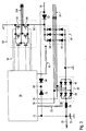
- the generator 26 (FIG. 2) is about the 3-pin line 30 to a first rectifier 38 and a second rectifier 40 connected.
- the two rectifiers 38, 40 are in the present exemplary embodiment constructed identically. They are both semi-controlled Bridge rectifier designed. They are everyone who Rectifier 38, 40 has three bridge branches for one each Phase of the three-phase current generated by the generator 26. In each Bridge branches are a diode and one designed as a thyristor Switching element in series between ground and one positive DC voltage connection switched. Exemplary 3 shows the diode and the switching element in one first bridge branch of the first rectifier 38 with the 44 and 44, and the diode and the Switching element in the corresponding bridge branch of the second Rectifiers 40 are designated by reference numerals 46 and 48, respectively. Three control lines 50, 52 each connect the Switching elements of the two rectifiers 38, 40 with the Control logic 36.
- the rectifiers 38, 40 be constructed differently.
- one of the rectifiers 38, 40 (or both) as a fully controlled rectifier with six switching elements or as an uncontrolled rectifier be designed with six diodes.
- the switching elements can use other electronic instead of thyristors Switches such as field effect transistors or IGBTs (insulated gate bipolar transistors) or bipolar transistors.
- the first rectifier 38 generates an internal DC voltage DC, which is applied to a three-phase controller 54.
- the three-phase controller 54 is used to generate the on the supply line 22A flowing three-phase current for the pump motor 18A.
- the three-phase controller has 54 a bridge branch connected to the DC voltage DC with two switching elements connected in series.
- the switching elements of such a bridge branch are in Fig. 3 designated by way of example with the reference numerals 56 and 58.
- a total of six control lines 60 connect the Control inputs of the switching elements of the three-phase controller 54 with the control logic 36.
- the Switching elements of the three-phase controller 54 designed as IGBTs. In alternative versions, however, others can Switching elements such as field effect transistors or those mentioned above in connection with the rectifiers 38, 40 Components are used.
- the generator 26 In normal operation of the aircraft engine according to FIGS. 2 and 3 the generator 26 generates sufficient energy for supply of the entire electrical system.
- This three-phase current on the Line 30 is rectified by second rectifier 40. After filtering through that from the inductor 68 and the capacitor 70 formed low-pass filter is from second rectifier 40 delivered DC voltage across the On-board electrical system output 32 fed into the general on-board electrical system and also serves (via the third diode 74) for supply the control logic 36.
- the switching elements of the second rectifier 40 are from the control logic 36 is controlled via the control lines 52, in order to control the level of the Onboard power supply output 32 applied DC voltage to 270 V. hold.
- the actual value of this DC voltage is used for this regulation from control logic 36 via the voltage control input 72 measured.
- Control logic 36 also receives over the phase inputs 76 and 78 are used to control the second Rectifier 40 needed information regarding the Phase position of the three-phase phases on line 30.
- the control logic 36 also determines from suitable measurement and Input values the current fuel consumption of the Turbine assembly 10 and from it the required speed the fuel pump 12. From this speed, the Control logic 36 values for the frequency and voltage of the the supply line 22A to be applied to the pump motor 18A Three-phase current. In the exemplary embodiment described here the voltage and frequency of the three-phase current are approximate proportional to each other. In alternative versions however, depending on the characteristics of the pump motor 18A, another frequency / voltage relationship implemented become.
- the control logic sets 36 first fixes a value for the DC voltage DC, which is slightly higher than the three-phase voltage to be achieved is.
- This DC voltage DC is generated by the control logic 36, by providing suitable switching signals for the switching elements of the first rectifier 38 to the control lines 50 creates.
- the first rectifier 38 works here as well the second rectifier 40 in a phase control mode.
- the control logic 36 also generates suitable control signals for the switching elements of the three-phase controller 54 in order from the DC voltage the three-phase supply for the Pump motor 18A with the voltage and frequency characteristics mentioned above to create. For each phase of the three-phase current a bridge branch of the three-phase controller 54 in a pulse width modulation method controlled to a approximately sinusoidal voltage curve with the desired one To obtain effective voltage.
- Control of the first rectifier 38 has the advantage that even in operating modes with very slow pump speeds a reasonable duty cycle (pulse-pause ratio) of the Three-phase controller 54 can be achieved.
- a reasonable duty cycle pulse-pause ratio
- Alternating versions are used to generate three-phase current however, by the three-phase controller 54 from one constant DC voltage, which is as high as the highest required three-phase voltage.
- suitable filters for the Three-phase current may be provided.
- the one at the external supply input is used first 34 applied voltage to supply the Control logic 36 (via the second diode 64) and the three-phase controller 54 (via the first diode 62).
- this Period of external supply is the duty cycle of the Three-phase controller 54 is usually very low because of the External supply voltage of 270 V as DC voltage bears directly on the three-phase controller 54. Therefore, as soon as the generator 26 generates a sufficient voltage, the external supply (by one not shown in the figures Switch) interrupted.
- the two are Rectifiers 38, 40, as already mentioned as an option above, as a fully controlled rectifier with six each Switching elements designed. Accordingly, too six control lines 50, 52 for the rectifiers 38, 40 4 (only three control lines 52 are shown in FIG. 4) shown). As a further difference from FIG. 3, the 4, three phase inputs 76, 78, 80 on to the three phases of the transmitted on line 30 Three-phase current are connected.
- This embodiment has the advantage that it can also be used for one External supply voltage of more than the vehicle electrical system voltage can be used.
- a filter choke 88 is in a phase of each the three-phase controller 54 generated three-phase current for the pump motor 18A switched. Through this LC filtering in the direct current range and the additional filtering in the three-phase range can reduce electromagnetic interference and improves the running characteristics of the pump motor 18A become. Adequate interference suppression is available in design variants already through the low-pass filter in the direct current range or achieved by the filter chokes 88.
- FIGS. 4 and 3 are identical, so that reference is made to the above description. Further embodiment variants of the invention are provided in which the assemblies shown in FIGS. 3 and 4 are arbitrary are combined.
Landscapes
- Engineering & Computer Science (AREA)
- Chemical & Material Sciences (AREA)
- Combustion & Propulsion (AREA)
- Mechanical Engineering (AREA)
- General Engineering & Computer Science (AREA)
- Control Of Eletrric Generators (AREA)
- Control Of Vehicle Engines Or Engines For Specific Uses (AREA)
Applications Claiming Priority (2)
| Application Number | Priority Date | Filing Date | Title |
|---|---|---|---|
| DE19908531 | 1999-02-28 | ||
| DE1999108531 DE19908531A1 (de) | 1999-02-28 | 1999-02-28 | Kraftstoffpumpenantrieb eines Flugtriebwerks und Flugtriebwerk |
Publications (2)
| Publication Number | Publication Date |
|---|---|
| EP1031716A2 true EP1031716A2 (fr) | 2000-08-30 |
| EP1031716A3 EP1031716A3 (fr) | 2001-02-07 |
Family
ID=7899077
Family Applications (1)
| Application Number | Title | Priority Date | Filing Date |
|---|---|---|---|
| EP00102674A Withdrawn EP1031716A3 (fr) | 1999-02-28 | 2000-02-09 | Réacteur d'avion et système de commande de la pompe à carburant d'un réacteur d'avion |
Country Status (2)
| Country | Link |
|---|---|
| EP (1) | EP1031716A3 (fr) |
| DE (1) | DE19908531A1 (fr) |
Cited By (3)
| Publication number | Priority date | Publication date | Assignee | Title |
|---|---|---|---|---|
| US20100253168A1 (en) * | 2007-10-10 | 2010-10-07 | Mtu Aero Engines Gmbh | Electric drive, particularly for a fuel metering unit for an airplane engine |
| WO2018204376A1 (fr) * | 2017-05-01 | 2018-11-08 | Carter Fuel Systems | Pompe à combustible à débit variable dotée de moteur bldc, et module de commande associé |
| FR3116566A1 (fr) * | 2020-11-25 | 2022-05-27 | Safran Aircraft Engines | Dispositif d’actionnement de pompe, système de pompage, aéronef et procédé d’alimentation en carburant associés |
Families Citing this family (1)
| Publication number | Priority date | Publication date | Assignee | Title |
|---|---|---|---|---|
| DE102007054947A1 (de) | 2007-11-17 | 2009-05-20 | Mtu Aero Engines Gmbh | Zentrifugalpumpe mit einer erhöhten Betriebssicherheit |
Family Cites Families (7)
| Publication number | Priority date | Publication date | Assignee | Title |
|---|---|---|---|---|
| US2881330A (en) * | 1956-08-01 | 1959-04-07 | Ford Motor Co | Differential drive |
| DE3528519A1 (de) * | 1985-08-08 | 1987-02-19 | Kloeckner Humboldt Deutz Ag | Gasturbinentriebwerk mit einer generatoreinrichtung |
| JPH0442559Y2 (fr) * | 1985-10-03 | 1992-10-07 | ||
| JPS62247786A (ja) * | 1986-04-17 | 1987-10-28 | Aisan Ind Co Ltd | 電動式燃料供給ポンプの駆動制御回路 |
| JPH02161196A (ja) * | 1988-12-12 | 1990-06-21 | Aisan Ind Co Ltd | 電動式燃料ポンプ |
| DE4036905A1 (de) * | 1989-11-25 | 1991-05-29 | Bosch Gmbh Robert | Antriebssystem fuer eine kraftstoff-foerderpumpe in verbindung mit einer brennkraftmaschine eines kraftfahrzeuges |
| WO1998025014A2 (fr) * | 1996-12-03 | 1998-06-11 | Elliott Energy Systems, Inc. | Systeme electrique de turboalternateur sur arbre commun |
-
1999
- 1999-02-28 DE DE1999108531 patent/DE19908531A1/de not_active Ceased
-
2000
- 2000-02-09 EP EP00102674A patent/EP1031716A3/fr not_active Withdrawn
Non-Patent Citations (1)
| Title |
|---|
| None |
Cited By (6)
| Publication number | Priority date | Publication date | Assignee | Title |
|---|---|---|---|---|
| US20100253168A1 (en) * | 2007-10-10 | 2010-10-07 | Mtu Aero Engines Gmbh | Electric drive, particularly for a fuel metering unit for an airplane engine |
| WO2018204376A1 (fr) * | 2017-05-01 | 2018-11-08 | Carter Fuel Systems | Pompe à combustible à débit variable dotée de moteur bldc, et module de commande associé |
| US10495019B2 (en) | 2017-05-01 | 2019-12-03 | Carter Fuel Systems | Variable output fuel pump having a BLDC motor and control module therefor |
| FR3116566A1 (fr) * | 2020-11-25 | 2022-05-27 | Safran Aircraft Engines | Dispositif d’actionnement de pompe, système de pompage, aéronef et procédé d’alimentation en carburant associés |
| WO2022112713A1 (fr) * | 2020-11-25 | 2022-06-02 | Safran Aircraft Engines | Dispositif d'actionnement de pompe, systeme de pompage, aeronef et procede d'alimentation en carburant associes |
| US12519410B2 (en) | 2020-11-25 | 2026-01-06 | Safran Aircraft Engines | Pump actuating device, and associated pumping system, aircraft and fuel supply method |
Also Published As
| Publication number | Publication date |
|---|---|
| EP1031716A3 (fr) | 2001-02-07 |
| DE19908531A1 (de) | 2000-09-07 |
Similar Documents
| Publication | Publication Date | Title |
|---|---|---|
| EP0212471B1 (fr) | Turbine à gaz avec génératrice | |
| DE69936796T2 (de) | Dynamotor für ein hybridfahrzeug und verfahren zu seiner regelung | |
| DE3810871C3 (de) | Elektrisches Servolenkungs-Regelsystem | |
| DE69216365T2 (de) | Stromversorgungsvorrichtung für ein Fahrzeug | |
| DE69420589T2 (de) | Geschalteter reluktanz-starter/generator regelsystem mit der möglichkeit des regenerativen betriebs und elektrisches system zu dessen anwendung | |
| DE69214602T2 (de) | Antriebsregelvorrichtung für ein in Folge geschaltetes Hybridfahrzeug | |
| DE19538946C1 (de) | Elektronisch kommutierter Elektromotor für Solaranwendung | |
| EP2776272B1 (fr) | Procédé et dispositif de commande d'un moteur électrique | |
| DE602004003643T2 (de) | Elektrizitätserzeugungssystem mit fester Frequenz und Verfahren zur Steuerung desselben | |
| DE69626770T2 (de) | Antriebssystem für ein Hybrid angetriebenes Kraftfahrzeug und zugehöriges Steuerungsverfahren | |
| DE19733208C1 (de) | Schaltungsanordnung für eine Drehstrom-Lichtmaschine eines Kraftfahrzeuges und Verfahren zur Ansteuerung der Schaltungsanordnung | |
| WO1998021805A1 (fr) | Systeme d'alimentation electrique | |
| DE3041201A1 (de) | Verfahren und vorrichtung zur besseren ausnutzung der stromabgabe, insbesondere von drehstormgeneratoren bei kraftfahrzeugen | |
| DE3126149A1 (de) | Elektrisches flugzeugtriebwerkstart- und generators ystem | |
| DE102007048071A1 (de) | Verfahren und System zum Übertragen von Schaltinformationen eines Spannungsreglers an einen Fahrzeugcomputer | |
| DE69000330T2 (de) | Elektrische generator-anlasservorrichtung, insbesondere zur anwendung als generator und anlasser fuer kraftfahrzeuge. | |
| EP0178446A1 (fr) | Dispositif de hacheur à semi-conducteur | |
| DE69217118T2 (de) | Elektrische Antriebsvorrichtung eines Fahrzeugs und mit einer derartigen Vorrichtung ausgerüstetes Kraftfahrzeug | |
| DE19518991A1 (de) | Verfahren zum Betrieb eines elektronisch kommutierten Motors, und Motor zur Durchführung eines solchen Verfahrens | |
| DE3124102A1 (de) | "verfahren und vorrichtung zur steuerung des antriebs eines wechselstromgenerators" | |
| DE102018201321A1 (de) | Verfahren zum Betreiben einer Anordnung aus einer elektrischen Maschine und einem Gleichrichter | |
| EP1031716A2 (fr) | Réacteur d'avion et système de commande de la pompe à carburant d'un réacteur d'avion | |
| DE10148246A1 (de) | Regelung und elektrisches System für Impulsaufladung einer Anlasser-Drehstromlichtmaschine | |
| EP0109519B2 (fr) | Moteur asynchrone triphasé | |
| DE3021864C2 (fr) |
Legal Events
| Date | Code | Title | Description |
|---|---|---|---|
| PUAI | Public reference made under article 153(3) epc to a published international application that has entered the european phase |
Free format text: ORIGINAL CODE: 0009012 |
|
| AK | Designated contracting states |
Kind code of ref document: A2 Designated state(s): AT BE CH CY DE DK ES FI FR GB GR IE IT LI LU MC NL PT SE |
|
| AX | Request for extension of the european patent |
Free format text: AL;LT;LV;MK;RO;SI |
|
| PUAL | Search report despatched |
Free format text: ORIGINAL CODE: 0009013 |
|
| AK | Designated contracting states |
Kind code of ref document: A3 Designated state(s): AT BE CH CY DE DK ES FI FR GB GR IE IT LI LU MC NL PT SE |
|
| AX | Request for extension of the european patent |
Free format text: AL;LT;LV;MK;RO;SI |
|
| RIC1 | Information provided on ipc code assigned before grant |
Free format text: 7F 02C 7/22 A, 7F 02C 7/32 B |
|
| RAP1 | Party data changed (applicant data changed or rights of an application transferred) |
Owner name: MTU AERO ENGINES GMBH |
|
| STAA | Information on the status of an ep patent application or granted ep patent |
Free format text: STATUS: THE APPLICATION HAS BEEN WITHDRAWN |
|
| 18W | Application withdrawn |
Withdrawal date: 20010317 |