EP1031764A1 - Dispositif de transmission pour véhicules automobiles, poulie utilisé dans celui-ci et procédé de fabrication d'une telle poulie - Google Patents
Dispositif de transmission pour véhicules automobiles, poulie utilisé dans celui-ci et procédé de fabrication d'une telle poulie Download PDFInfo
- Publication number
- EP1031764A1 EP1031764A1 EP00200530A EP00200530A EP1031764A1 EP 1031764 A1 EP1031764 A1 EP 1031764A1 EP 00200530 A EP00200530 A EP 00200530A EP 00200530 A EP00200530 A EP 00200530A EP 1031764 A1 EP1031764 A1 EP 1031764A1
- Authority
- EP
- European Patent Office
- Prior art keywords
- contact surfaces
- pulley
- transmission unit
- transmission
- polished
- Prior art date
- Legal status (The legal status is an assumption and is not a legal conclusion. Google has not performed a legal analysis and makes no representation as to the accuracy of the status listed.)
- Granted
Links
Images
Classifications
-
- F—MECHANICAL ENGINEERING; LIGHTING; HEATING; WEAPONS; BLASTING
- F16—ENGINEERING ELEMENTS AND UNITS; GENERAL MEASURES FOR PRODUCING AND MAINTAINING EFFECTIVE FUNCTIONING OF MACHINES OR INSTALLATIONS; THERMAL INSULATION IN GENERAL
- F16H—GEARING
- F16H57/00—General details of gearing
- F16H57/04—Features relating to lubrication or cooling or heating
-
- F—MECHANICAL ENGINEERING; LIGHTING; HEATING; WEAPONS; BLASTING
- F16—ENGINEERING ELEMENTS AND UNITS; GENERAL MEASURES FOR PRODUCING AND MAINTAINING EFFECTIVE FUNCTIONING OF MACHINES OR INSTALLATIONS; THERMAL INSULATION IN GENERAL
- F16H—GEARING
- F16H55/00—Elements with teeth or friction surfaces for conveying motion; Worms, pulleys or sheaves for gearing mechanisms
- F16H55/32—Friction members
- F16H55/36—Pulleys
-
- B—PERFORMING OPERATIONS; TRANSPORTING
- B24—GRINDING; POLISHING
- B24B—MACHINES, DEVICES, OR PROCESSES FOR GRINDING OR POLISHING; DRESSING OR CONDITIONING OF ABRADING SURFACES; FEEDING OF GRINDING, POLISHING, OR LAPPING AGENTS
- B24B29/00—Machines or devices for polishing surfaces on work by means of tools made of soft or flexible material with or without the application of solid or liquid polishing agents
- B24B29/02—Machines or devices for polishing surfaces on work by means of tools made of soft or flexible material with or without the application of solid or liquid polishing agents designed for particular workpieces
- B24B29/04—Machines or devices for polishing surfaces on work by means of tools made of soft or flexible material with or without the application of solid or liquid polishing agents designed for particular workpieces for rotationally symmetrical workpieces, e.g. ball-, cylinder- or cone-shaped workpieces
-
- F—MECHANICAL ENGINEERING; LIGHTING; HEATING; WEAPONS; BLASTING
- F16—ENGINEERING ELEMENTS AND UNITS; GENERAL MEASURES FOR PRODUCING AND MAINTAINING EFFECTIVE FUNCTIONING OF MACHINES OR INSTALLATIONS; THERMAL INSULATION IN GENERAL
- F16G—BELTS, CABLES, OR ROPES, PREDOMINANTLY USED FOR DRIVING PURPOSES; CHAINS; FITTINGS PREDOMINANTLY USED THEREFOR
- F16G5/00—V-belts, i.e. belts of tapered cross-section
- F16G5/16—V-belts, i.e. belts of tapered cross-section consisting of several parts
- F16G5/163—V-belts, i.e. belts of tapered cross-section consisting of several parts with means allowing lubrication
-
- F—MECHANICAL ENGINEERING; LIGHTING; HEATING; WEAPONS; BLASTING
- F16—ENGINEERING ELEMENTS AND UNITS; GENERAL MEASURES FOR PRODUCING AND MAINTAINING EFFECTIVE FUNCTIONING OF MACHINES OR INSTALLATIONS; THERMAL INSULATION IN GENERAL
- F16H—GEARING
- F16H55/00—Elements with teeth or friction surfaces for conveying motion; Worms, pulleys or sheaves for gearing mechanisms
- F16H55/32—Friction members
- F16H55/52—Pulleys or friction discs of adjustable construction
- F16H55/56—Pulleys or friction discs of adjustable construction of which the bearing parts are relatively axially adjustable
-
- F—MECHANICAL ENGINEERING; LIGHTING; HEATING; WEAPONS; BLASTING
- F16—ENGINEERING ELEMENTS AND UNITS; GENERAL MEASURES FOR PRODUCING AND MAINTAINING EFFECTIVE FUNCTIONING OF MACHINES OR INSTALLATIONS; THERMAL INSULATION IN GENERAL
- F16H—GEARING
- F16H9/00—Gearings for conveying rotary motion with variable gear ratio, or for reversing rotary motion, by endless flexible members
- F16H9/02—Gearings for conveying rotary motion with variable gear ratio, or for reversing rotary motion, by endless flexible members without members having orbital motion
- F16H9/24—Gearings for conveying rotary motion with variable gear ratio, or for reversing rotary motion, by endless flexible members without members having orbital motion using chains or toothed belts, belts in the form of links; Chains or belts specially adapted to such gearing
Definitions
- the present invention concerns a transmission unit for motor vehicles, a pulley used thereby, as well as a method for making such a pulley.
- a transmission unit containing a continuous variable transmission, consisting of an ingoing shaft, a driven shaft, two pulleys situated on the ingoing shaft and the driven shaft respectively, and an endless transmission element provided between said pulleys, whereby the above-mentioned pulleys each consist of two pulley halves with conical contact surfaces which can be axially adjusted in relation to one another, such that the transmission ratio between the ingoing shaft and the driven shaft can be continuously altered.
- a transmission element which consists of a lubricated belt which is provided with metal parts having contact surfaces which work in conjunction with the above-mentioned conical contact surfaces of the pulley halves.
- the metal parts are connected as such by means of flexible elements, such as cords or such.
- the belt is lubricated by exposing the belt and/or the pulley halves to oil and/or a cooling liquid. This can be done in any way whatsoever. As described in European patent No. 0.574.085, this can be done for example by squirting the oil and/or the cooling liquid on the transmission element and/or the pulleys by means of one or several feed pipes.
- the contact surfaces of the pulley halves are finished by means of conventional polishing.
- the invention aims a transmission unit with a transmission element which makes use of the principle of thin-film lubrication, but whereby the above-mentioned disadvantages are excluded with certainty.
- the invention concerns a transmission unit of the type containing a continuous variable transmission consisting of an ingoing shaft, a driven shaft, two pulleys situated on the ingoing shaft and the driven shaft respectively, and an endless transmission element provided between said pulleys, whereby the above-mentioned pulleys each consist of two pulley halves with conical contact surfaces which can be axially adjusted in relation to one another, such that the transmission ratio between the ingoing shaft and the driven shaft can be continuously altered, whereby the transmission element consists of a lubricated belt which is provided with metal parts having contact surfaces which work in conjunction with the above-mentioned conical contact surfaces of the pulley halves, and whereby the contact surfaces of the parts have a profiling, in particular a profiling procuring a thin-film lubrication, characterized in that the conical contact surfaces of the pulley halves concerned are polished.
- the contact surface of the pulley halves is particularly smooth, and there are no two rough surfaces acting on one another, which finally has for a result that the profiled contact surface of the above-mentioned parts will always smoothly adjust to the contact surface of the pulley halves. This guarantees a stable wear-in.
- the profile of the contact surfaces of the above-mentioned parts can be of any nature whatsoever and may for example consist of a punched profile, a corrugated profile or a profile formed of local recesses which are obtained for example by sandblasting the surface concerned.
- the conical contact surfaces are preferably polished with a cloth with particles or with a polishing block.
- they are preferably polished by means of a rotating polishing movement. Thanks to this rotating polishing movement is obtained a very smooth surface.
- the roughnesses on the contact surface of the pulley halves can never co-operate with the profiling on the contact surfaces of the above-mentioned parts, and an unstable wear-in is once more counteracted.
- the invention also concerns a pulley for realizing the above-mentioned transmission unit, characterized in that it is provided with one or several conical contact surfaces which are polished.
- the invention also concerns a method for realizing such a pulley, characterized in that, at the time of the final finishing, the conical contact surfaces are polished with a rotating polishing element.
- a polishing element is hereby preferably used which has such a diameter that this polishing element covers the entire or almost entire radial length of the conical contact surface. As the entire radial length is covered at once, the creation of roughnesses is minimized.
- polishing element as it carries out a rotating movement around its own axis, is moved over the contact surface of the pulley half to be worked, such according to a circular path in relation to said pulley half.
- the pulley half to be worked is driven in a rotating manner, and the rotating polishing element is represented to the rotating contact surface in a fixed place.
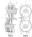
- the invention concerns a transmission unit 1 containing a continuous variable transmission 2, consisting of an ingoing shaft 3, a driven shaft 4, two pulleys 5-6 situated on the ingoing shaft 3 and the driven shaft 4 respectively, and an endless transmission element 7 provided between said pulleys 5-6.
- the pulleys 5-6 each consist of two pulley halves 8-9 and 10-11 with conical contact surfaces 12.
- the pulley halves 8-9, 10-11 respectively can be axially adjusted in relation to one another, such that the transmission ratio between the ingoing shaft 3 and the driven shaft 4 can be continuously altered.
- the above-mentioned transmission element 7 consists of a lubricated belt which is provided with metal parts 13 having contact surfaces 14 which work in conjunction with the above-mentioned conical contact surfaces 12.
- the lubrication can be carried out in any way whatsoever. In the given example, this is done by means of a belt lubricating pipe 15 via which a number of squirts of oil and/or cooling liquid 16 are squirted on the transmission element 7 and/or on the pulleys 5-6.
- metal parts 13 can be linked to one another in any way whatsoever. Examples thereof are sufficiently known from the state of the art and consequently are not further described here.
- the invention specifically concerns embodiments whereby the contact surfaces 14 have a profiling which procures a thin-film lubrication.
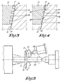
- An example of such a profiling 17 is represented in figure 3.
- Use is hereby made of a corrugated profile, preferably obtained by means of punching. It should be noted that in reality, the roughnesses of this profiling 17 are very small.
- the ribs 18 will for example have top sides with a width of a few hundreds of a millimeter, whereas they have a height of for example 0-03 mm.
- a thin-film lubrication is meant that the oil film 19 which is present on certain places on the contact surfaces 12 is entirely or almost entirely displaced locally, so that a metal-on-metal contact is obtained and the risk of slipping is minimized. Thanks to the use of a profiling 17 as mentioned above, such a thin-film lubrication is obtained, as the protruding parts of the profiling 17 can easily penetrate in the oil film 19.
- the invention is special in that a combination is made of the use of contact surfaces 14 which are provided with such a profiling 17 on the one hand, and the use of contact surfaces 12 which are polished on the other hand.
- two profilings namely the above-mentioned wanted profiling 17 on the one hand, and a profiling due to a too rough finishing of the contact surfaces 12 on the other hand, start acting on one another, as a result of which the wanted profiling 17 would disappear in no time due to wear.
- the profiling 17 can be of any nature whatsoever. As an example is given a profiling 17 with local recesses 20 in figure 4, resulting from the sandblasting of the contact surface 14, such in combination with a contact surface 12 which is polished in compliance with the invention.
- the contact surfaces 12 are preferably polished in a manner as represented in figure 5.
- the conical contact surfaces 12 are hereby treated with a rotating polishing element 21, in particular a polishing block. This is represented in figure 5 for one pulley half, but it is clear that the other pulley halves can be treated in a similar manner.
- a polishing element 21 is preferably used hereby, having such a diameter D that this polishing element 21 covers the entire or almost the entire radial length of the conical contact surface 12, whereby the distance indicated by 'R' in figure 5 is meant by this radial length.
- the polishing element 21 is moved over the contact surface 12 of the pulley half to be treated according to a circular path in relation to this pulley half, while carrying out a rotating movement around its own axis 22, which is realized by driving the pulley half to be treated around its axis 23 in a rotating manner, and by representing the rotating polishing element 21 to the rotating contact surface 12 in a fixed place.
- 'oil' is implied any type of lubricant and/or cooling medium.
- 'metal' parts are understood parts which are exclusively made of metal, as well as parts made of hard materials having a hardness which can be compared to that of the metal parts, as well as parts made of other materials, but whose contact surfaces 12 are made of metal or a material which is comparable as far as hardness is concerned.
- every pulley half 8-9-10-11 is preferably polished, it is clear that the invention also concerns embodiments whereby only one or a restricted number of the contact surfaces 12 are polished.
Landscapes
- Engineering & Computer Science (AREA)
- General Engineering & Computer Science (AREA)
- Mechanical Engineering (AREA)
- Pulleys (AREA)
- Transmissions By Endless Flexible Members (AREA)
- General Details Of Gearings (AREA)
- Connection Of Motors, Electrical Generators, Mechanical Devices, And The Like (AREA)
- Finish Polishing, Edge Sharpening, And Grinding By Specific Grinding Devices (AREA)
- Friction Gearing (AREA)
Applications Claiming Priority (2)
| Application Number | Priority Date | Filing Date | Title |
|---|---|---|---|
| BE9900119A BE1012482A3 (nl) | 1999-02-24 | 1999-02-24 | Transmissie-eenheid voor motorvoertuigen, riemschijf hierbij aangewend en werkwijze voor het vervaardigen van zulke riemschijf. |
| BE9900119 | 1999-02-24 |
Publications (2)
| Publication Number | Publication Date |
|---|---|
| EP1031764A1 true EP1031764A1 (fr) | 2000-08-30 |
| EP1031764B1 EP1031764B1 (fr) | 2003-11-26 |
Family
ID=3891776
Family Applications (1)
| Application Number | Title | Priority Date | Filing Date |
|---|---|---|---|
| EP00200530A Expired - Lifetime EP1031764B1 (fr) | 1999-02-24 | 2000-02-17 | Dispositif de transmission pour véhicules automobiles |
Country Status (7)
| Country | Link |
|---|---|
| US (1) | US6537166B1 (fr) |
| EP (1) | EP1031764B1 (fr) |
| JP (1) | JP2000240745A (fr) |
| KR (1) | KR100680629B1 (fr) |
| AT (1) | ATE255209T1 (fr) |
| BE (1) | BE1012482A3 (fr) |
| DE (1) | DE60006729T2 (fr) |
Cited By (3)
| Publication number | Priority date | Publication date | Assignee | Title |
|---|---|---|---|---|
| EP1455114A3 (fr) * | 2003-03-06 | 2005-03-23 | Nissan Motor Co., Ltd. | Courroie en V métallique |
| WO2006021186A1 (fr) * | 2004-08-24 | 2006-03-02 | Luk Lamellen Und Kupplungsbau Beteiligungs Kg | Transmission a poulies coniques et a courroie, son procede de production, et vehicule equipe de cette transmission |
| EP2187098A4 (fr) * | 2007-09-18 | 2011-03-23 | Honda Motor Co Ltd | Dispositif de lubrification pour transmission à variation continue de type courroie |
Families Citing this family (22)
| Publication number | Priority date | Publication date | Assignee | Title |
|---|---|---|---|---|
| US6640733B2 (en) * | 1999-12-08 | 2003-11-04 | Edward H. Huffmeyer | Inclinometer-controlled apparatus for varying the rate of seed population |
| NL1017122C2 (nl) * | 2001-01-16 | 2002-07-17 | Doornes Transmissie Bv | Dwarselement voor een drijfriem voor een continu variabele transmissie. |
| ATE527471T1 (de) * | 2003-02-28 | 2011-10-15 | Yamaha Motor Co Ltd | Stufenlose geschwindigkeitswechselvorrichtung der bandart |
| US7276002B2 (en) * | 2003-10-23 | 2007-10-02 | General Motors Corporation | Surface texture configuration for CVT pulley |
| KR100692125B1 (ko) * | 2003-10-30 | 2007-03-12 | 현대자동차주식회사 | 무단 변속기의 벨트 윤활 제어장치 |
| NL1027808C2 (nl) * | 2004-12-17 | 2006-06-20 | Bosch Gmbh Robert | Werkwijze voor het vormen van een dwarselement voor een duwband voor een continu variabele transmissie. |
| JP4851105B2 (ja) * | 2005-03-07 | 2012-01-11 | バンドー化学株式会社 | ベルト伝動装置 |
| US20060205321A1 (en) * | 2005-03-11 | 2006-09-14 | United Technologies Corporation | Super-abrasive machining tool and method of use |
| ITTO20050495A1 (it) * | 2005-07-19 | 2007-01-20 | Dayco Europe Srl | Gruppo puleggia con frizione perfezionata per una trasmissione a rapporto variabile con continuita' |
| WO2007043104A1 (fr) * | 2005-09-30 | 2007-04-19 | Honda Motor Co., Ltd. | Transmission à variation continue à courroie et son procédé de fonctionnement |
| JP4582086B2 (ja) * | 2006-12-13 | 2010-11-17 | トヨタ自動車株式会社 | 無段変速機用ベルト |
| JP2008232410A (ja) * | 2007-03-23 | 2008-10-02 | Jatco Ltd | 無段変速機および無段変速機の製造方法 |
| JP4641319B2 (ja) * | 2008-05-12 | 2011-03-02 | ジヤトコ株式会社 | 無段変速機用ベルト |
| JP5166473B2 (ja) * | 2010-03-31 | 2013-03-21 | ジヤトコ株式会社 | チェーン式無段変速装置及びその組立方法 |
| NL1039559C2 (en) * | 2012-04-23 | 2013-10-28 | Bosch Gmbh Robert | Belt-and-pulley-type continuously variable transmission. |
| JP6061028B2 (ja) * | 2013-05-17 | 2017-01-18 | トヨタ自動車株式会社 | 無段変速機 |
| JP6108321B2 (ja) * | 2015-07-16 | 2017-04-05 | 本田技研工業株式会社 | ベルト式無段変速機 |
| EP3228903B1 (fr) * | 2016-04-06 | 2018-07-25 | Cimco Marine AB | Dispositif permettant de transférer une puissance de rotation, machine comprenant un tel dispositif et utilisation d'un tel dispositif |
| NL1042205B1 (en) * | 2016-12-30 | 2018-07-23 | Bosch Gmbh Robert | Method for operating a continuously variable transmission incorporating a drive belt in a motor vehicle |
| CN108468594B (zh) * | 2017-02-23 | 2023-10-03 | 宇通客车股份有限公司 | 汽车空调压缩机传动结构及使用该传动结构的汽车 |
| JP6809368B2 (ja) * | 2017-05-16 | 2021-01-06 | アイシン・エィ・ダブリュ株式会社 | 無段変速機および伝動ベルト |
| BE1025361B9 (nl) | 2017-07-05 | 2019-03-11 | Punch Powertrain Nv | Smeer- en/of koelinrichting voor, en een continu variabele transmissie systeem met een dergelijke smeer- en/of koelinrichting |
Citations (4)
| Publication number | Priority date | Publication date | Assignee | Title |
|---|---|---|---|---|
| GB1549403A (en) * | 1975-10-09 | 1979-08-08 | Doornes Transmissie Bv | V-belt transmission |
| US4794741A (en) * | 1985-04-12 | 1989-01-03 | Van Doorne's Transmissie B.V. | Apparatus for machining transverse elements of a metal driving belt |
| EP0381258A1 (fr) * | 1989-02-03 | 1990-08-08 | Van Doorne's Transmissie B.V. | Transmission comprenant une courroie et des poulies en "V" |
| EP0574085A1 (fr) | 1992-06-11 | 1993-12-15 | VCST, naamloze vennootschap | Transmission pour véhicules à moteur avec refroidissement et/ou lubrification |
Family Cites Families (9)
| Publication number | Priority date | Publication date | Assignee | Title |
|---|---|---|---|---|
| JPS60252839A (ja) * | 1984-05-30 | 1985-12-13 | Toyota Motor Corp | 伝導ベルト用ブロツクおよびその製造方法 |
| JPS622058A (ja) * | 1985-06-27 | 1987-01-08 | Nippon Denso Co Ltd | 車両用無段変速機 |
| JPS62274140A (ja) * | 1986-05-23 | 1987-11-28 | Mitsuboshi Belting Ltd | 動力伝動装置 |
| JP2686973B2 (ja) * | 1988-07-14 | 1997-12-08 | スズキ株式会社 | ベルト駆動式無段変速機用ディスクの製法 |
| JP2748479B2 (ja) * | 1988-12-29 | 1998-05-06 | スズキ株式会社 | 車両用無段自動変速機 |
| BE1008462A3 (nl) * | 1994-06-21 | 1996-05-07 | Vcst Nv | Werkwijze voor het smeren en/of koelen van een transmissie-eenheid bij motorvoertuigen en transmissie-eenheid die deze werkwijze toepast. |
| NL1000087C2 (nl) * | 1995-04-07 | 1996-10-08 | Doornes Transmissie Bv | Continu variabele transmissie. |
| JPH10296599A (ja) * | 1997-04-22 | 1998-11-10 | Mitsuboshi Belting Ltd | Vベルトの自動バリ取り装置と自動バリ取り方法 |
| JP3186651B2 (ja) * | 1997-06-30 | 2001-07-11 | 日産自動車株式会社 | Vベルト式無段変速機構 |
-
1999
- 1999-02-24 BE BE9900119A patent/BE1012482A3/nl not_active IP Right Cessation
-
2000
- 2000-02-17 AT AT00200530T patent/ATE255209T1/de not_active IP Right Cessation
- 2000-02-17 DE DE60006729T patent/DE60006729T2/de not_active Expired - Fee Related
- 2000-02-17 EP EP00200530A patent/EP1031764B1/fr not_active Expired - Lifetime
- 2000-02-24 US US09/512,308 patent/US6537166B1/en not_active Expired - Fee Related
- 2000-02-24 KR KR1020000009024A patent/KR100680629B1/ko not_active Expired - Fee Related
- 2000-02-24 JP JP2000047851A patent/JP2000240745A/ja active Pending
Patent Citations (4)
| Publication number | Priority date | Publication date | Assignee | Title |
|---|---|---|---|---|
| GB1549403A (en) * | 1975-10-09 | 1979-08-08 | Doornes Transmissie Bv | V-belt transmission |
| US4794741A (en) * | 1985-04-12 | 1989-01-03 | Van Doorne's Transmissie B.V. | Apparatus for machining transverse elements of a metal driving belt |
| EP0381258A1 (fr) * | 1989-02-03 | 1990-08-08 | Van Doorne's Transmissie B.V. | Transmission comprenant une courroie et des poulies en "V" |
| EP0574085A1 (fr) | 1992-06-11 | 1993-12-15 | VCST, naamloze vennootschap | Transmission pour véhicules à moteur avec refroidissement et/ou lubrification |
Cited By (6)
| Publication number | Priority date | Publication date | Assignee | Title |
|---|---|---|---|---|
| EP1455114A3 (fr) * | 2003-03-06 | 2005-03-23 | Nissan Motor Co., Ltd. | Courroie en V métallique |
| US7261656B2 (en) | 2003-03-06 | 2007-08-28 | Nissan Motor Co., Ltd. | Metal V-belt |
| WO2006021186A1 (fr) * | 2004-08-24 | 2006-03-02 | Luk Lamellen Und Kupplungsbau Beteiligungs Kg | Transmission a poulies coniques et a courroie, son procede de production, et vehicule equipe de cette transmission |
| EP2187098A4 (fr) * | 2007-09-18 | 2011-03-23 | Honda Motor Co Ltd | Dispositif de lubrification pour transmission à variation continue de type courroie |
| CN101784821B (zh) * | 2007-09-18 | 2012-11-07 | 本田技研工业株式会社 | 皮带式无级变速器的润滑装置 |
| US8672097B2 (en) | 2007-09-18 | 2014-03-18 | Honda Motor Co., Ltd | Lubrication device for belt type continuously variable transmission |
Also Published As
| Publication number | Publication date |
|---|---|
| KR20000058176A (ko) | 2000-09-25 |
| US6537166B1 (en) | 2003-03-25 |
| BE1012482A3 (nl) | 2000-11-07 |
| DE60006729T2 (de) | 2004-09-30 |
| EP1031764B1 (fr) | 2003-11-26 |
| DE60006729D1 (de) | 2004-01-08 |
| JP2000240745A (ja) | 2000-09-05 |
| ATE255209T1 (de) | 2003-12-15 |
| KR100680629B1 (ko) | 2007-02-09 |
Similar Documents
| Publication | Publication Date | Title |
|---|---|---|
| EP1031764B1 (fr) | Dispositif de transmission pour véhicules automobiles | |
| KR100568400B1 (ko) | 볼나사 너트, 그 볼나사 너트를 사용한 직선 안내장치 및 스티어링용 볼나사 및 볼나사 너트의 제조방법 | |
| EP1169256B1 (fr) | Conception de poulie amelioree | |
| Kragelsky et al. | Friction wear lubrication: tribology handbook | |
| US6877351B2 (en) | Linear guide rail and method for working same | |
| US5863239A (en) | Microfinishing and roller burnishing machine | |
| DE102005014191B4 (de) | Verfahren zur Herstellung einer Riemenscheibe für ein stufenloses Riemengetriebe | |
| JP4024122B2 (ja) | ピストンエンジン用のシリンダライナーの製造方法 | |
| US6736404B1 (en) | Shaft for use with annular seal assembly and method of manufacturing same | |
| US5281189A (en) | Crowned pulley for a belt conveyor | |
| US6460236B1 (en) | Apparatus for producing wrapped slip tubes | |
| US3965765A (en) | Pulley | |
| JP2002147456A (ja) | すべり軸受 | |
| JP5593210B2 (ja) | 無段変速機用プーリおよびベルト式無段変速機 | |
| EP0692341B1 (fr) | Mandrin en particulier pour l'usinage du marbre et similaire | |
| JPH0556415B2 (fr) | ||
| CN113108033A (zh) | 带式无级变速机及其制造方法 | |
| EP1893889B1 (fr) | Courroie de transmission pour transmission à variation continue et procédé de fabrication d élément transversal pour ladite courroie de transmission | |
| JP2006527830A (ja) | 金属駆動ベルト | |
| SU1733159A1 (ru) | Валок дл холодной обработки давлением листового материала | |
| NL1043518B1 (en) | A method for manufacturing a transverse segment for a drive belt and a drive belt including the thus manufactured transverse segment | |
| RU2160661C2 (ru) | Абразивный круг (варианты) | |
| RU2115534C1 (ru) | Способ суперфиниширования желоба колец шариковых подшипников | |
| RU2071901C1 (ru) | Способ двустороннего торцового шлифования | |
| JPS61116147A (ja) | ベルト式無段変速機用ベルトブロツク |
Legal Events
| Date | Code | Title | Description |
|---|---|---|---|
| PUAI | Public reference made under article 153(3) epc to a published international application that has entered the european phase |
Free format text: ORIGINAL CODE: 0009012 |
|
| AK | Designated contracting states |
Kind code of ref document: A1 Designated state(s): AT BE CH CY DE DK ES FI FR GB GR IE IT LI LU MC NL PT SE |
|
| AX | Request for extension of the european patent |
Free format text: AL;LT;LV;MK;RO;SI |
|
| 17P | Request for examination filed |
Effective date: 20010110 |
|
| AKX | Designation fees paid |
Free format text: AT BE CH CY DE DK ES FI FR GB GR IE IT LI LU MC NL PT SE |
|
| 17Q | First examination report despatched |
Effective date: 20020618 |
|
| GRAH | Despatch of communication of intention to grant a patent |
Free format text: ORIGINAL CODE: EPIDOS IGRA |
|
| RTI1 | Title (correction) |
Free format text: TRANSMISSION UNIT FOR MOTOR VEHICLES |
|
| GRAS | Grant fee paid |
Free format text: ORIGINAL CODE: EPIDOSNIGR3 |
|
| GRAA | (expected) grant |
Free format text: ORIGINAL CODE: 0009210 |
|
| AK | Designated contracting states |
Kind code of ref document: B1 Designated state(s): AT BE CH CY DE DK ES FI FR GB GR IE IT LI LU MC NL PT SE |
|
| PG25 | Lapsed in a contracting state [announced via postgrant information from national office to epo] |
Ref country code: IT Free format text: LAPSE BECAUSE OF FAILURE TO SUBMIT A TRANSLATION OF THE DESCRIPTION OR TO PAY THE FEE WITHIN THE PRESCRIBED TIME-LIMIT;WARNING: LAPSES OF ITALIAN PATENTS WITH EFFECTIVE DATE BEFORE 2007 MAY HAVE OCCURRED AT ANY TIME BEFORE 2007. THE CORRECT EFFECTIVE DATE MAY BE DIFFERENT FROM THE ONE RECORDED. Effective date: 20031126 Ref country code: LI Free format text: LAPSE BECAUSE OF FAILURE TO SUBMIT A TRANSLATION OF THE DESCRIPTION OR TO PAY THE FEE WITHIN THE PRESCRIBED TIME-LIMIT Effective date: 20031126 Ref country code: FR Free format text: LAPSE BECAUSE OF FAILURE TO SUBMIT A TRANSLATION OF THE DESCRIPTION OR TO PAY THE FEE WITHIN THE PRESCRIBED TIME-LIMIT Effective date: 20031126 Ref country code: AT Free format text: LAPSE BECAUSE OF FAILURE TO SUBMIT A TRANSLATION OF THE DESCRIPTION OR TO PAY THE FEE WITHIN THE PRESCRIBED TIME-LIMIT Effective date: 20031126 Ref country code: NL Free format text: LAPSE BECAUSE OF FAILURE TO SUBMIT A TRANSLATION OF THE DESCRIPTION OR TO PAY THE FEE WITHIN THE PRESCRIBED TIME-LIMIT Effective date: 20031126 Ref country code: CY Free format text: LAPSE BECAUSE OF FAILURE TO SUBMIT A TRANSLATION OF THE DESCRIPTION OR TO PAY THE FEE WITHIN THE PRESCRIBED TIME-LIMIT Effective date: 20031126 Ref country code: CH Free format text: LAPSE BECAUSE OF FAILURE TO SUBMIT A TRANSLATION OF THE DESCRIPTION OR TO PAY THE FEE WITHIN THE PRESCRIBED TIME-LIMIT Effective date: 20031126 Ref country code: FI Free format text: LAPSE BECAUSE OF FAILURE TO SUBMIT A TRANSLATION OF THE DESCRIPTION OR TO PAY THE FEE WITHIN THE PRESCRIBED TIME-LIMIT Effective date: 20031126 |
|
| REG | Reference to a national code |
Ref country code: GB Ref legal event code: FG4D |
|
| REG | Reference to a national code |
Ref country code: CH Ref legal event code: EP |
|
| REF | Corresponds to: |
Ref document number: 60006729 Country of ref document: DE Date of ref document: 20040108 Kind code of ref document: P |
|
| REG | Reference to a national code |
Ref country code: IE Ref legal event code: FG4D |
|
| PG25 | Lapsed in a contracting state [announced via postgrant information from national office to epo] |
Ref country code: IE Free format text: LAPSE BECAUSE OF NON-PAYMENT OF DUE FEES Effective date: 20040217 Ref country code: LU Free format text: LAPSE BECAUSE OF NON-PAYMENT OF DUE FEES Effective date: 20040217 |
|
| PG25 | Lapsed in a contracting state [announced via postgrant information from national office to epo] |
Ref country code: GR Free format text: LAPSE BECAUSE OF FAILURE TO SUBMIT A TRANSLATION OF THE DESCRIPTION OR TO PAY THE FEE WITHIN THE PRESCRIBED TIME-LIMIT Effective date: 20040226 Ref country code: SE Free format text: LAPSE BECAUSE OF FAILURE TO SUBMIT A TRANSLATION OF THE DESCRIPTION OR TO PAY THE FEE WITHIN THE PRESCRIBED TIME-LIMIT Effective date: 20040226 Ref country code: DK Free format text: LAPSE BECAUSE OF FAILURE TO SUBMIT A TRANSLATION OF THE DESCRIPTION OR TO PAY THE FEE WITHIN THE PRESCRIBED TIME-LIMIT Effective date: 20040226 |
|
| PG25 | Lapsed in a contracting state [announced via postgrant information from national office to epo] |
Ref country code: MC Free format text: LAPSE BECAUSE OF NON-PAYMENT OF DUE FEES Effective date: 20040228 |
|
| PG25 | Lapsed in a contracting state [announced via postgrant information from national office to epo] |
Ref country code: ES Free format text: LAPSE BECAUSE OF FAILURE TO SUBMIT A TRANSLATION OF THE DESCRIPTION OR TO PAY THE FEE WITHIN THE PRESCRIBED TIME-LIMIT Effective date: 20040309 |
|
| NLV1 | Nl: lapsed or annulled due to failure to fulfill the requirements of art. 29p and 29m of the patents act | ||
| REG | Reference to a national code |
Ref country code: CH Ref legal event code: PL |
|
| PLBE | No opposition filed within time limit |
Free format text: ORIGINAL CODE: 0009261 |
|
| STAA | Information on the status of an ep patent application or granted ep patent |
Free format text: STATUS: NO OPPOSITION FILED WITHIN TIME LIMIT |
|
| 26N | No opposition filed |
Effective date: 20040827 |
|
| REG | Reference to a national code |
Ref country code: IE Ref legal event code: MM4A |
|
| EN | Fr: translation not filed | ||
| PGFP | Annual fee paid to national office [announced via postgrant information from national office to epo] |
Ref country code: GB Payment date: 20070216 Year of fee payment: 8 |
|
| PGFP | Annual fee paid to national office [announced via postgrant information from national office to epo] |
Ref country code: DE Payment date: 20070420 Year of fee payment: 8 |
|
| PG25 | Lapsed in a contracting state [announced via postgrant information from national office to epo] |
Ref country code: PT Free format text: LAPSE BECAUSE OF NON-PAYMENT OF DUE FEES Effective date: 20040426 |
|
| GBPC | Gb: european patent ceased through non-payment of renewal fee |
Effective date: 20080217 |
|
| PG25 | Lapsed in a contracting state [announced via postgrant information from national office to epo] |
Ref country code: DE Free format text: LAPSE BECAUSE OF NON-PAYMENT OF DUE FEES Effective date: 20080902 |
|
| PG25 | Lapsed in a contracting state [announced via postgrant information from national office to epo] |
Ref country code: GB Free format text: LAPSE BECAUSE OF NON-PAYMENT OF DUE FEES Effective date: 20080217 |
|
| REG | Reference to a national code |
Ref country code: BE Ref legal event code: HC Owner name: PUNCH POWERTRAIN NV; BE Free format text: DETAILS ASSIGNMENT: CHANGE OF OWNER(S), CHANGEMENT NOM PROPRIETAIRE; FORMER OWNER NAME: ZF GETRIEBE N.V. SINT TRUIDEN Effective date: 20170711 |
|
| REG | Reference to a national code |
Ref country code: BE Ref legal event code: PD Owner name: PUNCH POWERTRAIN NV; BE Free format text: DETAILS ASSIGNMENT: CHANGE OF OWNER(S), AUTRE, CHANGEMENT D'ADRESSE Effective date: 20181203 |
|
| PGFP | Annual fee paid to national office [announced via postgrant information from national office to epo] |
Ref country code: BE Payment date: 20190218 Year of fee payment: 20 |
|
| REG | Reference to a national code |
Ref country code: BE Ref legal event code: MK Effective date: 20200217 |