EP1031773A2 - Joint d'étanchéité pour fluide - Google Patents
Joint d'étanchéité pour fluide Download PDFInfo
- Publication number
- EP1031773A2 EP1031773A2 EP99123359A EP99123359A EP1031773A2 EP 1031773 A2 EP1031773 A2 EP 1031773A2 EP 99123359 A EP99123359 A EP 99123359A EP 99123359 A EP99123359 A EP 99123359A EP 1031773 A2 EP1031773 A2 EP 1031773A2
- Authority
- EP
- European Patent Office
- Prior art keywords
- sealing
- sealing element
- molded part
- area
- opening
- Prior art date
- Legal status (The legal status is an assumption and is not a legal conclusion. Google has not performed a legal analysis and makes no representation as to the accuracy of the status listed.)
- Granted
Links
Images
Classifications
-
- F—MECHANICAL ENGINEERING; LIGHTING; HEATING; WEAPONS; BLASTING
- F16—ENGINEERING ELEMENTS AND UNITS; GENERAL MEASURES FOR PRODUCING AND MAINTAINING EFFECTIVE FUNCTIONING OF MACHINES OR INSTALLATIONS; THERMAL INSULATION IN GENERAL
- F16J—PISTONS; CYLINDERS; SEALINGS
- F16J15/00—Sealings
- F16J15/02—Sealings between relatively-stationary surfaces
- F16J15/06—Sealings between relatively-stationary surfaces with solid packing compressed between sealing surfaces
- F16J15/062—Sealings between relatively-stationary surfaces with solid packing compressed between sealing surfaces characterised by the geometry of the seat
-
- F—MECHANICAL ENGINEERING; LIGHTING; HEATING; WEAPONS; BLASTING
- F16—ENGINEERING ELEMENTS AND UNITS; GENERAL MEASURES FOR PRODUCING AND MAINTAINING EFFECTIVE FUNCTIONING OF MACHINES OR INSTALLATIONS; THERMAL INSULATION IN GENERAL
- F16J—PISTONS; CYLINDERS; SEALINGS
- F16J15/00—Sealings
- F16J15/02—Sealings between relatively-stationary surfaces
- F16J15/021—Sealings between relatively-stationary surfaces with elastic packing
- F16J15/022—Sealings between relatively-stationary surfaces with elastic packing characterised by structure or material
- F16J15/024—Sealings between relatively-stationary surfaces with elastic packing characterised by structure or material the packing being locally weakened in order to increase elasticity
- F16J15/025—Sealings between relatively-stationary surfaces with elastic packing characterised by structure or material the packing being locally weakened in order to increase elasticity and with at least one flexible lip
Definitions
- the invention relates to a method for producing a liquid seal and a ring-like sealing element for liquid-tight connection of a connecting line to an in a solidification process molded part, in particular made of polymer concrete, which for guiding and / or receiving Liquids are formed, especially for connection to a drainage channel, an inlet box or the like Drainage device.
- Such molded parts can have a connection opening with a have closed circumferential opening edge to a Connecting line, in particular for draining liquid, to connect.
- Connecting line in particular for draining liquid
- O-ring directly during the casting process pour in, so that the O-ring about half its cross-sectional area inside of the opening edge protrudes.
- suitable connecting cable into the one defined by the O-ring Ring opening introduced essentially results from of elastic restoring forces of the O-ring liquid-tight seat between the connecting line and the O-ring.
- the object of the present invention is a method and to specify a device of the type mentioned, with which a liquid-tight seat between the molded part and the sealing element can be produced.
- the liquid tight Seat should be especially when using materials for the Molding to be guaranteed during the Solidification process show a shrinkage behavior.
- this ring-like sealing element before curing the Opening edge of the molded part arranged on the opening edge, especially cast in during a casting process.
- the Sealing element has a connecting line sealing area on to form a liquid-tight seat between the Sealing element and the connecting line if the Connection line into that defined by the sealing element Ring opening is introduced.
- Sealing element in addition to one another Flow direction of the connection opening or ring opening extending molded part sealing area on the Outside of the connection line area in the circumferential direction of the Sealing element runs.
- the molded part sealing area becomes such arranged that a when curing the molding liquid-tight seat between the molded part and the Molding sealing area forms.
- the molded part sealing area is located here at least one-sided over the area of his Extension transverse to the flow direction on the material of the Molding.
- a comparatively large area between the Sealing element and the material of the molded part is formed. Smaller voids between the sealing element and the Material of the molded part is therefore edged on all sides and do not act as a leakage opening.
- the at least one molded part sealing region preferably extends approximately perpendicular to the flow direction the ring opening.
- the hardening process is the deformation of the Sealing element low.
- the molded part sealing area along its extension across Flow direction on both sides of the material of the molded part surrounded the shrinkage causes a pressing of the molding material to the sealing element.
- the molded part sealing area with at least one anchorage area connected, the transverse to the direction of extension of the molded part sealing area runs.
- the inventive method causes the embedding at least one anchoring area in the material of the Molding that on the sealing element one inside directed deductible is exercisable due to the Shape and arrangement of the anchoring area Counteracts counterforce. It is advantageous that the Contact surface of the molded part on the sealing element is enlarged. Is still the anchoring area sufficiently elastic, so the sealing element in this Area of shrinkage due to the material of the molded part deformed, d. H. the anchoring area follows the shrinking area Material. This results in the anchoring area particularly liquid-tight seat. Can the Anchoring area, however, when shrinking the molding material not follow, it offers a resistance to one also leads particularly liquid-tight press fit.
- the anchoring area can be designed in different ways.
- the molded part sealing area a rough and / or rib-like surface structure the anchoring area is formed. especially the Ribs preferably extend in the circumferential direction of the Sealing element.
- An anchoring area is also preferred, through a material area of the molded part backing, against the molded part sealing area angled region of the sealing element is formed becomes.
- a calibration body at least during part of the Solidification process in the connection opening of the molded part and lies against the inside of the sealing element a predefined position, orientation and / or dimensions of the Liquid seal and / or protection of the Ensure sealing element against aggressive substances.
- the Using a calibration body also has the effect that at least in places, the formation of a coating on the inside surface of the sealing element is avoided. Such deposits or dirt can cause leaks lead between the sealing element and a connecting line.
- the calibration body fixes the Sealing element and therefore prevents deformation of the Sealing element before shrinking. That way therefore high demands on accuracy and Reproducibility regarding the dimensioning of the Liquid seal can be fulfilled.
- the calibration body is preferably less than Elongation of the formed from elastic material Sealing element on the inside of the sealing element.
- the sealing element is therefore on the calibration body stretched and thus fixed particularly effectively.
- connection line sealing area of the Sealing element one in and / or against
- the opening width widening the direction of flow is the Calibration body preferably in at least two areas different opening widths on the inside of the Sealing element. With such supports Sealing element can thus be used in different areas Deformation can be avoided and the predetermined Opening width profile can be obtained. It is also on this Way a large coverage of the inner edge of the Sealing element achievable.
- a second calibration body is used the other opening side than the first calibration body in the Ring opening or the connection opening.
- the first and the second calibration body into one another. This leads to to a mutual fixation and support, so that the Relative position of the two calibration bodies is defined and unchanged throughout the solidification process can be maintained.
- the sealing element according to the invention preferably has the Inside of the connection line sealing area closed all-round sealing lip. This has the Advantage that even if the sealing element is deformed still a tight fit all around between the sealing element and a connecting line can be achieved.
- the sealing lip preferably has an inner edge sealing system on the connecting line, the Inner edge further seen in flow direction upstream as the outside approach of Sealing lip. Is in this training Liquid on the upstream side of the Sealing lip, becomes a with increasing fluid pressure growing contact force exerted on the sealing lip, so that the sealing effect is guaranteed.
- the connecting cable sealing area has a Flow direction initially tapering and again widening opening width, so that a line-like closed circumferential contact surface for the sealing system on the Connection line is formed. If a connecting line in the Introduced ring opening of the sealing element, the Outside width, especially the outside diameter of the Connection line is larger than the inside width on the line-like contact surface, so a press fit with good Sealing effect between the connecting line and the Formed sealing element.
- connection line sealing area on a section that with approximately the same opening width in Flow direction extends so that a flat liquid-tight seat can be formed with the connecting line is.
- connection line sealing area can be individually or in Combination with each other.
- connection line sealing area is both a line-like closed circumferential contact surface, as well as a Sealing lip and also a contact surface over one Section of constant opening width available. It arises thus a labyrinth-like seal that shows the advantages of Lip seals and press fit seals combined.
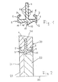
- the sealing element 1 shows a longitudinal section through a sealing element 1.
- the sealing element 1 is rotationally symmetrical to one Axis of rotation, below that shown in the figure Outline of the sealing element 1 in the image plane of the figure lies.
- the axis of rotation is not shown in Fig. 1.
- the sealing element 1 has a connecting line sealing area 2 on.
- the connection line sealing area 2 shows in the representation of the figure on its underside, the the inside of the one defined by the sealing element 1 Ring opening is a labyrinth-like sealing profile.
- a cylindrical contact surface 12 on the inside which is inserted into the ring opening when it is in contact with one Connection line forms a liquid-tight seat, if the connecting line has a corresponding outer diameter having.
- the sealing element consists of known elastic materials, especially made of acrylonitrile butadiene rubber (NBR). Therefore, a connecting line, the one has a slightly larger outer diameter than that Inner diameter of the sealing element 1 on the contact surface 12, introduced into the ring opening, the liquid-tight Seat due to the restoring forces of the elastic Sealing material causes.
- the Inner lip 13 Approximately in the middle of the connection line sealing area 2 there is a sealing lip 10 on the inside, the Inner lip 13 a significantly smaller opening width has as the cylindrical contact surface 12.
- the lip base 14 is seen in the flow direction (i.e. in the Representation of Figure 1 seen from left to right) downstream than the inner lip 13.
- connection line is from the right into the ring opening introduced and after fitting into the cylindrical contact surface 12 inserted further into the ring opening, then the Sealing lip 10 with expanding its opening width its inside (in FIG. 1 on the inside lip of the lip 13 beginning and rising to the top right) to the Connecting cable.
- the sealing lip 10 thus causes effective liquid seal, even at high Fluid pressure is constant and caused by their "Tooth shape" an increased resistance to one Pull out a connecting cable once plugged in.
- the connecting line sealing area 2 Section Located further upstream is the Inside of the connecting line sealing area 2 Section in which the opening width first decreases and then increases again so that a line-like contact surface 11 is formed.
- the opening width is the line-like Contact surface 11 is less than the opening width of the cylindrical contact surface 12. Therefore, the connecting line Coming from the right beyond the sealing lip 10 further in inserted the ring opening, a press fit results between the line-like contact surface 11 and the Connection line with at least in a narrow section larger pressures between sealing element 1 and Connection line as on the cylindrical contact surface 12th
- the sealing element 1 forms the sealing element 1 a labyrinth-like seal that shows the known advantages of Press fit seals and lip seals combined and above also an additional sealing effect through the The presence of several, spaced apart contact surfaces shows.
- FIG. 2 is a detail of a Shaped part 21 shown in polymer concrete.
- the molding 21 is for example a drainage channel for the drainage of Floor surfaces, an inlet box or the like Drainage device.
- the molded part 21 in a connection opening in the area shown in FIG. 2, which is only shown in cross-section on one side.
- the in Fig. 2 arrangement is rotationally symmetrical to the Rotation axis 24.
- the connection opening is thus circular.
- the sealing element 1 has in addition to that Connection line sealing area 2 a total of three molded part sealing areas 3, 4, 5 on.
- the first molded part sealing area 3 is located at the outlet end of the Connection opening.
- the first molded part sealing area 3 extends essentially perpendicular to Flow direction of the ring opening or the connection opening and sits directly on the lead seal area 2 on. On its left, continue in the direction of flow upstream side is the material of the molded part 21 on the first molded part sealing area.
- the transverse to the direction of extension of the first molded part sealing area 3 runs.
- the sealing element 1 is fixed in the Anchored material of the molded part 21. Radially inwards Pulling forces pointing into the ring opening, for example when inserting a connecting cable into the ring opening occur can be accommodated by the molded part 21 without that loosening the anchorage or even breaking out of the Sealing element 1 occurs.
- the anchorage is still through the bulge-like, widening end of the outlet side Anchoring area 8 reinforced.
- the anchoring area 8 on the outlet side is such elastic that he in the manufacture of the through the molded part 21st and the sealing element 1 formed liquid seal 20 a movement caused by shrinkage of the polymer concrete can follow radially inward in the direction of the axis of rotation 24. At least in these areas of the sealing element 1 remains hence the polymer concrete material during theshrinking process in contact with the same places on the Surface of the sealing element 1, so that a particularly firm System and thus an effective liquid-tight seat is formed.
- the third molded part sealing area 5, which is located on the is located on the inlet end of the connection opening its outward end seen in the radial direction one anchoring area 7 on the inlet side.
- the arrangement of the Anchoring areas 7, 8 are mirror images of one another with respect to a mirror plane that is a central one Cross-sectional plane of the connection opening or ring opening is.
- the sealing element 1 has a second one Molding sealing area 4, which is a web-like Longitudinal section in the representation of Figures 1 and 2 shows and is therefore designed in the form of a disk ring overall.
- the second Molding sealing area 4 sets directly on the Connection line sealing area 2 and extends in radial direction by a multiple of the radial extent of the connecting line sealing area into the material of the Molding 21 into it. It is bilateral in the representation of 2 right and left, of the material of the molded part 21st surround.
- the second molded part sealing area 4 has one rib-like surface structure, with each of the two Sides four ring ribs 6 are arranged. Each of the ring ribs 6 runs around the entire ring opening.
- ring ribs 6 ensure secure anchoring of the second molded part sealing area 4 in the molded part 21 and on the other hand form essentially stationary structures that during the shrinking process of the polymer concrete this one To offer resistance. Especially on the tops, that is the radially outward sides of the ring ribs 6 come therefore during the shrinkage to press the polymer concrete material and thus a particularly reliable seal Investment. There may even be voids between the Polymer concrete and the ring ribs 6 during the Solidification process. A similar effect shows itself on the outside in the radial direction Edge of the second molded part sealing area 4, the total forms a cylindrical surface.
- the sealing element 1 is during the manufacturing process in which the molded part 21 receives its shape in the following manner with the molded part 21 connected.
- 2 shows a first 22 and a second 23 Calibration body shown, on which the sealing element 1 during the casting and the subsequent Solidification process, which is used to harden the polymer concrete leads, is stretched under slight local expansion.
- the Calibration body 22, 23 engage on the inside of the Ring opening of the sealing element 1 on this.
- the stretch the sealing element is significantly less than that by a connecting line caused expansion, which after Harden in the ring opening as already described is inserted.
- the liquid seal 20 described above fulfills at suitable calibration by means of the calibration bodies 22, 23 Dimensional requirements of DIN 19534 T1 (Push-fit socket with seal), also in terms of tightness hydraulic pressure, KIWA-WRL 5211 and, when installed in Soil, in terms of tightness of DIN 4060 (water resistance of pipe connections).
- the design of the sealing element 1 with a plurality of circumferential contact surfaces for investment to a connection line inserted into the ring opening further the advantage that a tightness even then is guaranteed if the connecting cable is not exactly coaxial is introduced into the ring opening or after the introduction forces acting transversely to the axis of rotation 24.
- the sealing lip 10 compensates for asymmetries.
- the Arrangement of those based on the press fit sealing principle line-like contact surface 11 and the cylindrical Contact surface 12 near the ends of the ring opening ensures an exact positioning of the connecting cable and prevents major deviations from the coaxial position.
Landscapes
- Engineering & Computer Science (AREA)
- General Engineering & Computer Science (AREA)
- Mechanical Engineering (AREA)
- Physics & Mathematics (AREA)
- Geometry (AREA)
- Gasket Seals (AREA)
- Lining And Supports For Tunnels (AREA)
- Sealing Using Fluids, Sealing Without Contact, And Removal Of Oil (AREA)
- Fuses (AREA)
- On-Site Construction Work That Accompanies The Preparation And Application Of Concrete (AREA)
Applications Claiming Priority (2)
| Application Number | Priority Date | Filing Date | Title |
|---|---|---|---|
| DE19907748A DE19907748C2 (de) | 1999-02-23 | 1999-02-23 | Flüssigkeitsdichtung |
| DE19907748 | 1999-02-23 |
Publications (3)
| Publication Number | Publication Date |
|---|---|
| EP1031773A2 true EP1031773A2 (fr) | 2000-08-30 |
| EP1031773A3 EP1031773A3 (fr) | 2002-12-11 |
| EP1031773B1 EP1031773B1 (fr) | 2006-03-22 |
Family
ID=7898551
Family Applications (1)
| Application Number | Title | Priority Date | Filing Date |
|---|---|---|---|
| EP99123359A Expired - Lifetime EP1031773B1 (fr) | 1999-02-23 | 1999-11-23 | Joint d'étanchéité pour fluide |
Country Status (4)
| Country | Link |
|---|---|
| EP (1) | EP1031773B1 (fr) |
| AT (1) | ATE321226T1 (fr) |
| DE (2) | DE19907748C2 (fr) |
| ES (1) | ES2259825T3 (fr) |
Cited By (1)
| Publication number | Priority date | Publication date | Assignee | Title |
|---|---|---|---|---|
| WO2015044217A1 (fr) * | 2013-09-25 | 2015-04-02 | Aktiebolaget Skf | Système d'étanchéité |
Families Citing this family (1)
| Publication number | Priority date | Publication date | Assignee | Title |
|---|---|---|---|---|
| DE202008014038U1 (de) | 2008-10-21 | 2010-03-11 | Haas, Thomas | Dichtung mit umbiegbarem Rand |
Family Cites Families (7)
| Publication number | Priority date | Publication date | Assignee | Title |
|---|---|---|---|---|
| DE2743501C3 (de) * | 1977-09-28 | 1981-01-08 | Fa. Carl Freudenberg, 6940 Weinheim | Dichtring |
| US4342462A (en) * | 1978-05-10 | 1982-08-03 | John Carlesimo | Adjustable seal member for conduit to manhole junction |
| US4333662A (en) * | 1980-12-09 | 1982-06-08 | Jones William D | Pipe seal |
| US4854543A (en) * | 1985-09-19 | 1989-08-08 | Les Industries Fortier Ltee | Apparatus for forming an opening with a gasket in a masonry manhole |
| DE4427603C1 (de) * | 1994-08-04 | 1995-07-27 | Norbert Heinker | Vorrichtung zur Abdichtung von Rohrleitungen, Kabelkanälen od.dgl. |
| DE19520510A1 (de) * | 1995-06-03 | 1996-12-05 | Buescher Pebueso Beton | Dichtungsanordnung für Betonrohre mit zwei integrierten Dichtungen |
| DE29619973U1 (de) * | 1996-11-16 | 1997-01-09 | Kunststoffröhren Sendenhorst GmbH, 48324 Sendenhorst | Betondichtung |
-
1999
- 1999-02-23 DE DE19907748A patent/DE19907748C2/de not_active Expired - Lifetime
- 1999-11-23 AT AT99123359T patent/ATE321226T1/de active
- 1999-11-23 DE DE59913249T patent/DE59913249D1/de not_active Expired - Lifetime
- 1999-11-23 ES ES99123359T patent/ES2259825T3/es not_active Expired - Lifetime
- 1999-11-23 EP EP99123359A patent/EP1031773B1/fr not_active Expired - Lifetime
Non-Patent Citations (1)
| Title |
|---|
| None |
Cited By (1)
| Publication number | Priority date | Publication date | Assignee | Title |
|---|---|---|---|---|
| WO2015044217A1 (fr) * | 2013-09-25 | 2015-04-02 | Aktiebolaget Skf | Système d'étanchéité |
Also Published As
| Publication number | Publication date |
|---|---|
| DE59913249D1 (de) | 2006-05-11 |
| EP1031773A3 (fr) | 2002-12-11 |
| DE19907748A1 (de) | 2000-11-16 |
| ATE321226T1 (de) | 2006-04-15 |
| ES2259825T3 (es) | 2006-10-16 |
| DE19907748C2 (de) | 2001-06-28 |
| EP1031773B1 (fr) | 2006-03-22 |
Similar Documents
| Publication | Publication Date | Title |
|---|---|---|
| DE606028T1 (de) | Abgedichtete Verbindung zwischen einem Rohr und einem Endstück und deren Verfahren zur Herstellung. | |
| CH643047A5 (de) | Verfahren zum herstellen von fittings fuer rohrverbindungen sowie werkzeug zur ausuebung des verfahrens und nach diesem verfahren hergestelltes fitting. | |
| DE2126740A1 (fr) | ||
| DE69603870T2 (de) | Modulare manschette zum schutz zur reparatur oder zur auskleidung einer rohrleitung | |
| DE9116780U1 (de) | Steckmuffenverbindung | |
| EP0634532A2 (fr) | Arrangement pour joint d'étanchéité pour élément de construction | |
| EP3553253B1 (fr) | Montage d'un coffrage de mur, système d'ancrage et douille | |
| DE69821599T2 (de) | Fitting zur Verstärkung einer Rohrverbindung | |
| DE2845308A1 (de) | Fitting o.dgl. aus formstabilem kunststoff fuer rohrverbindungen sowie verfahren und werkzeug zu seiner herstellung | |
| DE19542463B4 (de) | Rohrkupplung | |
| CH665464A5 (de) | Steckmuffendichtung an einem betonrohr. | |
| DE1925171A1 (de) | Verbindungsvorrichtung oder Kupplung | |
| EP1031773A2 (fr) | Joint d'étanchéité pour fluide | |
| DE3718619C2 (fr) | ||
| EP2226545B1 (fr) | Elément de conduite et utilisation correspondante | |
| DE1285809B (de) | Flanschverbindung fuer Wandteile von Druckgefaessen grossen Durchmessers | |
| DE2511302C3 (de) | Verfahren zur Herstellung eines Wellendichtringes | |
| DE2251082A1 (de) | Zugfeste verriegelung von kanalisationselementen | |
| DE69121548T2 (de) | Verbesserte Bandschelle mit keilförmigen, geschlitzten Nocken | |
| DE3232075A1 (de) | Dichtring fuer eine muffenrohrverbindung | |
| DE3031687C2 (de) | Vorrichtung zum Schutz der Endbereiche von Rohren gegen mechanische Beschädigungen | |
| EP2887478A1 (fr) | Intégration d'une conduite dans un élément de mur ou de sol | |
| DE3146272A1 (de) | "vorrichtung zur anbringung eines schlauches an einem anschlussstueck" | |
| DE20016604U1 (de) | Anschlußdichtung | |
| DE931325C (de) | Nachgiebige Verbindung starrer Rohrteile |
Legal Events
| Date | Code | Title | Description |
|---|---|---|---|
| PUAI | Public reference made under article 153(3) epc to a published international application that has entered the european phase |
Free format text: ORIGINAL CODE: 0009012 |
|
| AK | Designated contracting states |
Kind code of ref document: A2 Designated state(s): AT BE CH CY DE DK ES FI FR GB GR IE IT LI LU MC NL PT SE |
|
| AX | Request for extension of the european patent |
Free format text: AL;LT;LV;MK;RO;SI |
|
| PUAL | Search report despatched |
Free format text: ORIGINAL CODE: 0009013 |
|
| AK | Designated contracting states |
Kind code of ref document: A3 Designated state(s): AT BE CH CY DE DK ES FI FR GB GR IE IT LI LU MC NL PT SE |
|
| AX | Request for extension of the european patent |
Free format text: AL;LT;LV;MK;RO;SI |
|
| 17P | Request for examination filed |
Effective date: 20030311 |
|
| AKX | Designation fees paid |
Designated state(s): AT BE CH CY DE DK ES FI FR GB GR IE IT LI LU MC NL PT SE |
|
| 17Q | First examination report despatched |
Effective date: 20040122 |
|
| GRAP | Despatch of communication of intention to grant a patent |
Free format text: ORIGINAL CODE: EPIDOSNIGR1 |
|
| GRAS | Grant fee paid |
Free format text: ORIGINAL CODE: EPIDOSNIGR3 |
|
| GRAA | (expected) grant |
Free format text: ORIGINAL CODE: 0009210 |
|
| AK | Designated contracting states |
Kind code of ref document: B1 Designated state(s): AT BE CH CY DE DK ES FI FR GB GR IE IT LI LU MC NL PT SE |
|
| PG25 | Lapsed in a contracting state [announced via postgrant information from national office to epo] |
Ref country code: IT Free format text: LAPSE BECAUSE OF FAILURE TO SUBMIT A TRANSLATION OF THE DESCRIPTION OR TO PAY THE FEE WITHIN THE PRESCRIBED TIME-LIMIT;WARNING: LAPSES OF ITALIAN PATENTS WITH EFFECTIVE DATE BEFORE 2007 MAY HAVE OCCURRED AT ANY TIME BEFORE 2007. THE CORRECT EFFECTIVE DATE MAY BE DIFFERENT FROM THE ONE RECORDED. Effective date: 20060322 Ref country code: IE Free format text: LAPSE BECAUSE OF FAILURE TO SUBMIT A TRANSLATION OF THE DESCRIPTION OR TO PAY THE FEE WITHIN THE PRESCRIBED TIME-LIMIT Effective date: 20060322 |
|
| REG | Reference to a national code |
Ref country code: GB Ref legal event code: FG4D Free format text: NOT ENGLISH |
|
| REG | Reference to a national code |
Ref country code: CH Ref legal event code: EP |
|
| REG | Reference to a national code |
Ref country code: IE Ref legal event code: FG4D Free format text: LANGUAGE OF EP DOCUMENT: GERMAN |
|
| REF | Corresponds to: |
Ref document number: 59913249 Country of ref document: DE Date of ref document: 20060511 Kind code of ref document: P |
|
| GBT | Gb: translation of ep patent filed (gb section 77(6)(a)/1977) |
Effective date: 20060531 |
|
| PG25 | Lapsed in a contracting state [announced via postgrant information from national office to epo] |
Ref country code: SE Free format text: LAPSE BECAUSE OF FAILURE TO SUBMIT A TRANSLATION OF THE DESCRIPTION OR TO PAY THE FEE WITHIN THE PRESCRIBED TIME-LIMIT Effective date: 20060622 Ref country code: DK Free format text: LAPSE BECAUSE OF FAILURE TO SUBMIT A TRANSLATION OF THE DESCRIPTION OR TO PAY THE FEE WITHIN THE PRESCRIBED TIME-LIMIT Effective date: 20060622 |
|
| PG25 | Lapsed in a contracting state [announced via postgrant information from national office to epo] |
Ref country code: PT Free format text: LAPSE BECAUSE OF FAILURE TO SUBMIT A TRANSLATION OF THE DESCRIPTION OR TO PAY THE FEE WITHIN THE PRESCRIBED TIME-LIMIT Effective date: 20060822 |
|
| ET | Fr: translation filed | ||
| REG | Reference to a national code |
Ref country code: ES Ref legal event code: FG2A Ref document number: 2259825 Country of ref document: ES Kind code of ref document: T3 |
|
| REG | Reference to a national code |
Ref country code: IE Ref legal event code: FD4D |
|
| PG25 | Lapsed in a contracting state [announced via postgrant information from national office to epo] |
Ref country code: MC Free format text: LAPSE BECAUSE OF NON-PAYMENT OF DUE FEES Effective date: 20061130 Ref country code: LI Free format text: LAPSE BECAUSE OF NON-PAYMENT OF DUE FEES Effective date: 20061130 Ref country code: CH Free format text: LAPSE BECAUSE OF NON-PAYMENT OF DUE FEES Effective date: 20061130 |
|
| PLBE | No opposition filed within time limit |
Free format text: ORIGINAL CODE: 0009261 |
|
| STAA | Information on the status of an ep patent application or granted ep patent |
Free format text: STATUS: NO OPPOSITION FILED WITHIN TIME LIMIT |
|
| 26N | No opposition filed |
Effective date: 20061227 |
|
| REG | Reference to a national code |
Ref country code: CH Ref legal event code: PL |
|
| PG25 | Lapsed in a contracting state [announced via postgrant information from national office to epo] |
Ref country code: GR Free format text: LAPSE BECAUSE OF FAILURE TO SUBMIT A TRANSLATION OF THE DESCRIPTION OR TO PAY THE FEE WITHIN THE PRESCRIBED TIME-LIMIT Effective date: 20060623 |
|
| PG25 | Lapsed in a contracting state [announced via postgrant information from national office to epo] |
Ref country code: FI Free format text: LAPSE BECAUSE OF FAILURE TO SUBMIT A TRANSLATION OF THE DESCRIPTION OR TO PAY THE FEE WITHIN THE PRESCRIBED TIME-LIMIT Effective date: 20060322 |
|
| PG25 | Lapsed in a contracting state [announced via postgrant information from national office to epo] |
Ref country code: CY Free format text: LAPSE BECAUSE OF FAILURE TO SUBMIT A TRANSLATION OF THE DESCRIPTION OR TO PAY THE FEE WITHIN THE PRESCRIBED TIME-LIMIT Effective date: 20060322 |
|
| REG | Reference to a national code |
Ref country code: FR Ref legal event code: PLFP Year of fee payment: 17 |
|
| REG | Reference to a national code |
Ref country code: FR Ref legal event code: PLFP Year of fee payment: 18 |
|
| REG | Reference to a national code |
Ref country code: FR Ref legal event code: PLFP Year of fee payment: 19 |
|
| PGFP | Annual fee paid to national office [announced via postgrant information from national office to epo] |
Ref country code: NL Payment date: 20181122 Year of fee payment: 20 Ref country code: LU Payment date: 20181122 Year of fee payment: 20 |
|
| PGFP | Annual fee paid to national office [announced via postgrant information from national office to epo] |
Ref country code: DE Payment date: 20181122 Year of fee payment: 20 Ref country code: AT Payment date: 20181120 Year of fee payment: 20 |
|
| PGFP | Annual fee paid to national office [announced via postgrant information from national office to epo] |
Ref country code: BE Payment date: 20181122 Year of fee payment: 20 Ref country code: ES Payment date: 20181218 Year of fee payment: 20 Ref country code: GB Payment date: 20181126 Year of fee payment: 20 Ref country code: FR Payment date: 20181127 Year of fee payment: 20 Ref country code: IT Payment date: 20181122 Year of fee payment: 20 |
|
| REG | Reference to a national code |
Ref country code: DE Ref legal event code: R071 Ref document number: 59913249 Country of ref document: DE |
|
| REG | Reference to a national code |
Ref country code: NL Ref legal event code: MK Effective date: 20191122 |
|
| REG | Reference to a national code |
Ref country code: BE Ref legal event code: MK Effective date: 20191123 |
|
| REG | Reference to a national code |
Ref country code: GB Ref legal event code: PE20 Expiry date: 20191122 |
|
| REG | Reference to a national code |
Ref country code: AT Ref legal event code: MK07 Ref document number: 321226 Country of ref document: AT Kind code of ref document: T Effective date: 20191123 |
|
| PG25 | Lapsed in a contracting state [announced via postgrant information from national office to epo] |
Ref country code: GB Free format text: LAPSE BECAUSE OF EXPIRATION OF PROTECTION Effective date: 20191122 |
|
| REG | Reference to a national code |
Ref country code: ES Ref legal event code: FD2A Effective date: 20200721 |
|
| PG25 | Lapsed in a contracting state [announced via postgrant information from national office to epo] |
Ref country code: ES Free format text: LAPSE BECAUSE OF EXPIRATION OF PROTECTION Effective date: 20191124 |