EP1031776A2 - Combinaison buse d'injection/soupape pour améliorer le temps de réponse du dosage des couleurs - Google Patents
Combinaison buse d'injection/soupape pour améliorer le temps de réponse du dosage des couleurs Download PDFInfo
- Publication number
- EP1031776A2 EP1031776A2 EP00301492A EP00301492A EP1031776A2 EP 1031776 A2 EP1031776 A2 EP 1031776A2 EP 00301492 A EP00301492 A EP 00301492A EP 00301492 A EP00301492 A EP 00301492A EP 1031776 A2 EP1031776 A2 EP 1031776A2
- Authority
- EP
- European Patent Office
- Prior art keywords
- injector
- valve
- ball valve
- channel
- axis
- Prior art date
- Legal status (The legal status is an assumption and is not a legal conclusion. Google has not performed a legal analysis and makes no representation as to the accuracy of the status listed.)
- Granted
Links
- 230000004044 response Effects 0.000 title abstract description 10
- 239000003086 colorant Substances 0.000 claims abstract description 62
- 239000006260 foam Substances 0.000 claims abstract description 46
- 238000004040 coloring Methods 0.000 claims abstract description 22
- 229920002635 polyurethane Polymers 0.000 claims abstract description 14
- 239000004814 polyurethane Substances 0.000 claims abstract description 14
- 238000000034 method Methods 0.000 claims description 9
- 239000000758 substrate Substances 0.000 claims description 3
- 239000007788 liquid Substances 0.000 abstract description 14
- 239000002699 waste material Substances 0.000 abstract description 9
- 230000009467 reduction Effects 0.000 abstract description 5
- 230000002939 deleterious effect Effects 0.000 abstract description 4
- 229920005862 polyol Polymers 0.000 description 11
- 150000003077 polyols Chemical class 0.000 description 11
- 229920005830 Polyurethane Foam Polymers 0.000 description 7
- 238000004519 manufacturing process Methods 0.000 description 7
- 239000011496 polyurethane foam Substances 0.000 description 7
- 230000008859 change Effects 0.000 description 6
- 238000003860 storage Methods 0.000 description 6
- 239000000463 material Substances 0.000 description 5
- 239000000203 mixture Substances 0.000 description 5
- 239000006185 dispersion Substances 0.000 description 4
- 238000002347 injection Methods 0.000 description 4
- 239000007924 injection Substances 0.000 description 4
- 238000002156 mixing Methods 0.000 description 4
- 239000000049 pigment Substances 0.000 description 4
- 238000005086 pumping Methods 0.000 description 4
- 239000012948 isocyanate Substances 0.000 description 3
- 150000002513 isocyanates Chemical class 0.000 description 3
- 230000007246 mechanism Effects 0.000 description 3
- 238000013019 agitation Methods 0.000 description 2
- 238000013459 approach Methods 0.000 description 2
- 230000000712 assembly Effects 0.000 description 2
- 238000000429 assembly Methods 0.000 description 2
- UHZZMRAGKVHANO-UHFFFAOYSA-M chlormequat chloride Chemical compound [Cl-].C[N+](C)(C)CCCl UHZZMRAGKVHANO-UHFFFAOYSA-M 0.000 description 2
- 238000006073 displacement reaction Methods 0.000 description 2
- 238000007373 indentation Methods 0.000 description 2
- 230000004048 modification Effects 0.000 description 2
- 238000012986 modification Methods 0.000 description 2
- 230000006641 stabilisation Effects 0.000 description 2
- 238000011105 stabilization Methods 0.000 description 2
- 239000010935 stainless steel Substances 0.000 description 2
- 229910001220 stainless steel Inorganic materials 0.000 description 2
- 229910000975 Carbon steel Inorganic materials 0.000 description 1
- RTAQQCXQSZGOHL-UHFFFAOYSA-N Titanium Chemical compound [Ti] RTAQQCXQSZGOHL-UHFFFAOYSA-N 0.000 description 1
- 238000005452 bending Methods 0.000 description 1
- 230000008901 benefit Effects 0.000 description 1
- 230000000740 bleeding effect Effects 0.000 description 1
- 239000010962 carbon steel Substances 0.000 description 1
- 238000006243 chemical reaction Methods 0.000 description 1
- 238000004140 cleaning Methods 0.000 description 1
- 150000001875 compounds Chemical class 0.000 description 1
- 238000010924 continuous production Methods 0.000 description 1
- 238000005336 cracking Methods 0.000 description 1
- 230000003111 delayed effect Effects 0.000 description 1
- 230000001419 dependent effect Effects 0.000 description 1
- 238000013461 design Methods 0.000 description 1
- 238000010586 diagram Methods 0.000 description 1
- 230000000694 effects Effects 0.000 description 1
- 229920001971 elastomer Polymers 0.000 description 1
- 230000008030 elimination Effects 0.000 description 1
- 238000003379 elimination reaction Methods 0.000 description 1
- 239000012530 fluid Substances 0.000 description 1
- 230000004907 flux Effects 0.000 description 1
- 239000006261 foam material Substances 0.000 description 1
- 230000006872 improvement Effects 0.000 description 1
- 238000010348 incorporation Methods 0.000 description 1
- 230000000977 initiatory effect Effects 0.000 description 1
- 239000011344 liquid material Substances 0.000 description 1
- 239000002075 main ingredient Substances 0.000 description 1
- 238000005259 measurement Methods 0.000 description 1
- 230000003134 recirculating effect Effects 0.000 description 1
- 239000002904 solvent Substances 0.000 description 1
- 238000010186 staining Methods 0.000 description 1
- 239000000126 substance Substances 0.000 description 1
- 229910052719 titanium Inorganic materials 0.000 description 1
- 239000010936 titanium Substances 0.000 description 1
Images

Classifications
-
- F—MECHANICAL ENGINEERING; LIGHTING; HEATING; WEAPONS; BLASTING
- F16—ENGINEERING ELEMENTS AND UNITS; GENERAL MEASURES FOR PRODUCING AND MAINTAINING EFFECTIVE FUNCTIONING OF MACHINES OR INSTALLATIONS; THERMAL INSULATION IN GENERAL
- F16K—VALVES; TAPS; COCKS; ACTUATING-FLOATS; DEVICES FOR VENTING OR AERATING
- F16K5/00—Plug valves; Taps or cocks comprising only cut-off apparatus having at least one of the sealing faces shaped as a more or less complete surface of a solid of revolution, the opening and closing movement being predominantly rotary
- F16K5/06—Plug valves; Taps or cocks comprising only cut-off apparatus having at least one of the sealing faces shaped as a more or less complete surface of a solid of revolution, the opening and closing movement being predominantly rotary with plugs having spherical surfaces; Packings therefor
- F16K5/061—Plug valves; Taps or cocks comprising only cut-off apparatus having at least one of the sealing faces shaped as a more or less complete surface of a solid of revolution, the opening and closing movement being predominantly rotary with plugs having spherical surfaces; Packings therefor knee-joint
-
- B—PERFORMING OPERATIONS; TRANSPORTING
- B01—PHYSICAL OR CHEMICAL PROCESSES OR APPARATUS IN GENERAL
- B01F—MIXING, e.g. DISSOLVING, EMULSIFYING OR DISPERSING
- B01F35/00—Accessories for mixers; Auxiliary operations or auxiliary devices; Parts or details of general application
- B01F35/71—Feed mechanisms
- B01F35/712—Feed mechanisms for feeding fluids
-
- B—PERFORMING OPERATIONS; TRANSPORTING
- B01—PHYSICAL OR CHEMICAL PROCESSES OR APPARATUS IN GENERAL
- B01F—MIXING, e.g. DISSOLVING, EMULSIFYING OR DISPERSING
- B01F35/00—Accessories for mixers; Auxiliary operations or auxiliary devices; Parts or details of general application
- B01F35/71—Feed mechanisms
- B01F35/717—Feed mechanisms characterised by the means for feeding the components to the mixer
- B01F35/71805—Feed mechanisms characterised by the means for feeding the components to the mixer using valves, gates, orifices or openings
-
- B—PERFORMING OPERATIONS; TRANSPORTING
- B01—PHYSICAL OR CHEMICAL PROCESSES OR APPARATUS IN GENERAL
- B01F—MIXING, e.g. DISSOLVING, EMULSIFYING OR DISPERSING
- B01F35/00—Accessories for mixers; Auxiliary operations or auxiliary devices; Parts or details of general application
- B01F35/80—Forming a predetermined ratio of the substances to be mixed
- B01F35/83—Forming a predetermined ratio of the substances to be mixed by controlling the ratio of two or more flows, e.g. using flow sensing or flow controlling devices
- B01F35/834—Forming a predetermined ratio of the substances to be mixed by controlling the ratio of two or more flows, e.g. using flow sensing or flow controlling devices the flow of substances to be mixed circulating in a closed circuit, e.g. from a container through valve, driving means, metering means or dispensing means, e.g. 3-way valve, and back to the container
-
- B—PERFORMING OPERATIONS; TRANSPORTING
- B29—WORKING OF PLASTICS; WORKING OF SUBSTANCES IN A PLASTIC STATE IN GENERAL
- B29B—PREPARATION OR PRETREATMENT OF THE MATERIAL TO BE SHAPED; MAKING GRANULES OR PREFORMS; RECOVERY OF PLASTICS OR OTHER CONSTITUENTS OF WASTE MATERIAL CONTAINING PLASTICS
- B29B7/00—Mixing; Kneading
- B29B7/30—Mixing; Kneading continuous, with mechanical mixing or kneading devices
- B29B7/58—Component parts, details or accessories; Auxiliary operations
- B29B7/60—Component parts, details or accessories; Auxiliary operations for feeding, e.g. end guides for the incoming material
-
- B—PERFORMING OPERATIONS; TRANSPORTING
- B01—PHYSICAL OR CHEMICAL PROCESSES OR APPARATUS IN GENERAL
- B01F—MIXING, e.g. DISSOLVING, EMULSIFYING OR DISPERSING
- B01F2101/00—Mixing characterised by the nature of the mixed materials or by the application field
- B01F2101/2805—Mixing plastics, polymer material ingredients, monomers or oligomers
-
- B—PERFORMING OPERATIONS; TRANSPORTING
- B29—WORKING OF PLASTICS; WORKING OF SUBSTANCES IN A PLASTIC STATE IN GENERAL
- B29K—INDEXING SCHEME ASSOCIATED WITH SUBCLASSES B29B, B29C OR B29D, RELATING TO MOULDING MATERIALS OR TO MATERIALS FOR MOULDS, REINFORCEMENTS, FILLERS OR PREFORMED PARTS, e.g. INSERTS
- B29K2075/00—Use of PU, i.e. polyureas or polyurethanes or derivatives thereof, as moulding material
-
- B—PERFORMING OPERATIONS; TRANSPORTING
- B29—WORKING OF PLASTICS; WORKING OF SUBSTANCES IN A PLASTIC STATE IN GENERAL
- B29K—INDEXING SCHEME ASSOCIATED WITH SUBCLASSES B29B, B29C OR B29D, RELATING TO MOULDING MATERIALS OR TO MATERIALS FOR MOULDS, REINFORCEMENTS, FILLERS OR PREFORMED PARTS, e.g. INSERTS
- B29K2105/00—Condition, form or state of moulded material or of the material to be shaped
- B29K2105/0005—Condition, form or state of moulded material or of the material to be shaped containing compounding ingredients
- B29K2105/0032—Pigments, colouring agents or opacifiyng agents
-
- B—PERFORMING OPERATIONS; TRANSPORTING
- B29—WORKING OF PLASTICS; WORKING OF SUBSTANCES IN A PLASTIC STATE IN GENERAL
- B29K—INDEXING SCHEME ASSOCIATED WITH SUBCLASSES B29B, B29C OR B29D, RELATING TO MOULDING MATERIALS OR TO MATERIALS FOR MOULDS, REINFORCEMENTS, FILLERS OR PREFORMED PARTS, e.g. INSERTS
- B29K2105/00—Condition, form or state of moulded material or of the material to be shaped
- B29K2105/04—Condition, form or state of moulded material or of the material to be shaped cellular or porous
-
- Y—GENERAL TAGGING OF NEW TECHNOLOGICAL DEVELOPMENTS; GENERAL TAGGING OF CROSS-SECTIONAL TECHNOLOGIES SPANNING OVER SEVERAL SECTIONS OF THE IPC; TECHNICAL SUBJECTS COVERED BY FORMER USPC CROSS-REFERENCE ART COLLECTIONS [XRACs] AND DIGESTS
- Y10—TECHNICAL SUBJECTS COVERED BY FORMER USPC
- Y10T—TECHNICAL SUBJECTS COVERED BY FORMER US CLASSIFICATION
- Y10T137/00—Fluid handling
- Y10T137/8593—Systems
- Y10T137/85954—Closed circulating system
-
- Y—GENERAL TAGGING OF NEW TECHNOLOGICAL DEVELOPMENTS; GENERAL TAGGING OF CROSS-SECTIONAL TECHNOLOGIES SPANNING OVER SEVERAL SECTIONS OF THE IPC; TECHNICAL SUBJECTS COVERED BY FORMER USPC CROSS-REFERENCE ART COLLECTIONS [XRACs] AND DIGESTS
- Y10—TECHNICAL SUBJECTS COVERED BY FORMER USPC
- Y10T—TECHNICAL SUBJECTS COVERED BY FORMER US CLASSIFICATION
- Y10T137/00—Fluid handling
- Y10T137/8593—Systems
- Y10T137/86493—Multi-way valve unit
- Y10T137/86863—Rotary valve unit
- Y10T137/86871—Plug
-
- Y—GENERAL TAGGING OF NEW TECHNOLOGICAL DEVELOPMENTS; GENERAL TAGGING OF CROSS-SECTIONAL TECHNOLOGIES SPANNING OVER SEVERAL SECTIONS OF THE IPC; TECHNICAL SUBJECTS COVERED BY FORMER USPC CROSS-REFERENCE ART COLLECTIONS [XRACs] AND DIGESTS
- Y10—TECHNICAL SUBJECTS COVERED BY FORMER USPC
- Y10T—TECHNICAL SUBJECTS COVERED BY FORMER US CLASSIFICATION
- Y10T137/00—Fluid handling
- Y10T137/8593—Systems
- Y10T137/87571—Multiple inlet with single outlet
- Y10T137/87652—With means to promote mixing or combining of plural fluids
- Y10T137/8766—With selectively operated flow control means
Definitions
- This invention relates to an improved injector/valve combination which permits nearly immediate response time to an actuator signal.
- a combination is particularly suited for injecting colorants into polyurethane slabstock foam and permits a substantial reduction in foam waste due to low colorations during an on/off cycle.
- this invention combination comprises a novel ball valve which allows for instantaneous shut-off and -on without appreciable leakage or pressure drop and without the need to utilize a high throughput flow rate.
- Such a ball valve is used in combination with an injector which is actually attached to the valve, the configuration which permits continuous use and instantaneous on/off without a deleterious pressure drop and minimizes the possibility of turbulence as the liquid polymeric colorant flows through the injector.
- the ball valve, the attached injector configuration, the coloring apparatus comprising the inventive ball valve and/or the attached injector configuration, and the slabstock foam colored through the utilization of such an apparatus are also contemplated within this invention.
- Polymeric colorants i.e., polyoxyalkylenated colorants
- polyurethane slabstock foam i.e., in a continuous process
- pigment dispersion Prior to the utilization of such polymeric colorants, pigment dispersion were the main source of polyurethane coloring compounds.
- Such dispersions have traditionally proven very difficult to handle, too viscous for use within standard injectors, highly staining and thus difficult to clean from standard injector equipment (without the need for environmentally unfriendly solvents), and very abrasive and thus potentially damaging to the delicate machinery associated with coloring slabstock polyurethane foam.
- polymeric colorants are widely accepted as the best materials for coloring polyurethane foam.
- Polymeric colorants such as those cited above in Cross et al. were designed to. be totally miscible with one another as well as with most polyols, one of the two main ingredients used to produce polyurethane materials (isocyanates being the other).
- Pigment dispersions are particulates dispersed in some type of liquid carrier. They require a high degree of agitation before they satisfactorily blend together to provide a uniform color. As a result the short amount of time that the polyol and colorant are mixed in the typical slabstock foam machine's mixhead is not sufficient to produce in an adequate mixture of components to insure a single, homogeneous coloration throughout the target foam.
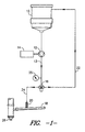
- FIG. 1 A configuration of this new (now typical) polymeric colorant production line for slabstock foam is depicted in FIG. 1 .
- This new coloring system itself generally consisted of 4 to 6 "primary" color storage tanks (one of which is depicted as 10 in FIG. 1 ) each feeding color to at least one positive displacement spur gear pump 12 coupled to a variable speed motor/drive 14 (such as available from Viking).
- the motor/pump combination 12, 14 was typically run continuously in either recirculation or dispense mode (depending on the position of a 3-way valve 16 ) to minimize the time required to spool up the motor 14 to the proper rpm and to ultimately achieve the pressure required to initiate color flow into a pre-mix manifold 18 through an injector 20 .
- the throughput pressure was typically measured through the utilization of a pressure gauge 25 attached to the feed line 13 from the pump 12 to the 3-way valve 16 .
- the typical 3-way valve 16 was air actuated and used to direct the flow of colorant from the recirculation feed line 22 to the dispense feed line 24 (to the injector 20 ) when color flow to the manifold 18 was required. From the manifold 18 , the colorant(s) was moved to the mixing head 26 and then further on to color the target slabstock foam (not illustrated).
- the market place demands that a foam producer be able to provide dark shades as well as light shades with a variety of hues and polyol flow rates. Since color is metered volumetrically a wide range of color flow rates are required to insure low enough flow for a minor component in a light shade.
- the polyol flow rates can be as low as 10 kg/min and as high as 300 kg/min [color loading is generally stated in parts per hundred polyol (php)]. As the rate at which the polyol flows is reduced so must the color rate be reduced to maintain the same php. For most foams manufactured in the United States the color delivery systems must be able to provide color flow as low a 2 grams/min and as high as 7000 grams/min or more.
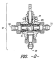
- the typical polyurethane slabstock foam coloring system has a three-way air actuated ball valve ( 28 in FIG. 2 ) that is positioned up near the polyol manifold. Due to the configuration of the available ball valves they are generally located approximately 1 meter from the manifold. As provided by the representation of a standard three-way ball valve assembly in FIG. 2 , material metered by the pump enters the top of the three-way ball valve 27 from the storage tank feed line 29 and exits either through the recirculation side 30 or the dispense side 32 depending on how the ball is oriented. FIG. 2 depicts the ball valve 27 when it is oriented in the recirculation mode.
- the ball valve 28 must typically rotate 180° from one side of the valve to the other (although there are some apparati which utilize a 90° ball valve rotation) through the movement of an actuator (not illustrated) attached to an actuator pin 34 which, in turn, fits into an identation (not illustrated) within the ball valve 27 .
- the typical ball valve 28 comprises a single channel 31 to accommodate the flow of colorant to either the recirculation side 30 or the dispense side 32 .
- This single channel is configured at a right angle and thus may contribute to laminar flow problems by requiring the colorant liquid to radically change direction, thereby altering the pressure over the total liquid mass (and thus producing non-uniformity of pressures over the entire liquid colorant).
- a device In addition to this 3-way valve, a device must be used to inject color away from the wall of the manifold to insure adequate subsequent mixing (i.e., to reduce the problems associated with laminar flow through a feed line having a larger diameter than the 3-way valve. Ideally, such a device should function as a check valve to maintain pressure in the line and to stop color flow when switching from dispense to recirculation. Such devices must maintain pressure after the dispensing unit is returned to recirculation mode otherwise the pressure drops below the "cracking" pressure of the check valve spring which will result in even longer startups which, in turn, may translate in to cost overruns or potentially greater amount of off-quality colored foam. Additionally, the resultant pressure drop must be acceptable across a broad delivery range for such injectors to alleviate any other related pressure difference problems.
- An entire colorant pumping system (such as discussed with regard to FIG. 1 , above) was developed to evaluate a variety of injection systems that closely resembles an actual production unit. It consisted of a spur gear pump from Viking coupled with a full flux vector motor and drive from Baldor. Stainless steel tubing having an outside diameter of 1 ⁇ 4 inch was connected to the discharge side of the pump. The distance from the pump to the 3-way valve was approximately 40 feet. The distance from the standard 3-way valve to the check valve was 3 feet. The motor/pump was run to insure pressure up through the 3 way valve and then it was allowed to dispense to insure that fluid filled the line under pressure from the valve to the check valve.
- Colorant response time (the time required for colorant to begin to flow from the three-way valve to the injector) was compared with throughput flow rate for this well known system. The results are tabulated below: Colorant Response Time (seconds) Flow Rate (g/min) 48 2.5 15 4 5 20 3 42 0 86
- Another object of the invention is to provide a significant improvement in coloring polyurethane slabstock foam over the prior art through the utilization of a two-channeled ball valve which allows for instantaneous on/off performance at a very wide range of throughput pressures.
- Yet another object of this invention is to provide an injector/valve assembly which substantially reduces the problems associated with laminar flow of liquid colorants or pigment dispersions in a coloring apparatus by permitting introduction of the colorant material away from the walls of the manifold thereby limiting the potential for deleterious turbulence (and thus potentially problematic resistance and pressure changes through the entire system).
- this invention provides a spherical ball valve having first and second channels
- a special 3-way valve was developed that comprises two exclusive channels that allows the valve to dispense from the bottom rather than feed from the bottom. In doing so the check valve was then connected directly to the bottom of the valve that would minimize the distance between the 3-way valve and manifold.
- a special "injector” was developed introducing color away from the wall of the manifold. This valve/injector configuration was tested in a similar manner as the standard configuration. The results was instantaneous flow regardless of the flow rate.
- this ball valve which is a spherical ball valve
- this ball valve comprises two exclusive channels, one of which is positioned to direct the flow of colorant to the recirculation assembly and the other to direct such a flow to the injector.
- the two separate channels be aligned on totally separate axes (for instance, one on the x-axis and the other on either the y- or z-axis). More specifically, the channel not on the x-axis must enter the spherical ball valve at a point referenced as 0 ° on the particular axis and exits the spherical ball valve at a point 90° on the same axis. In this manner, the two channels are completely exclusive of another, thereby facilitating movement of the valve between recirculation and dispensing modes. Furthermore, the configuration of the non-x-axis channel reduces the change of pressure on the liquid colorant through the valve than with a standard right angle bending channel (it provides a sort of shunt). Such a ball valve has proven to be invaluable in providing the necessary instantaneous on/off (color response) times as well as maintaining the proper flow rate (at an extremely wide range from about 0.3 g/min to about 14,000 g/min).
- An actuator is utilized, generally, to rotate this ball valve into these specific positions.
- Such an actuator includes a pin extending into the valve assembly, the end of which pin is shaped to fit an indentation in the ball valve. The actuator then turns the ball valve the requisite number of degrees to align the respective channel to the desired feed line (90° is preferred, although, in some instances, 180° may be possible).
- valve assembly and injector unit can be moved in close proximity of one another in order to provide substantial reductions in waste foam production as well.
- a unitary assembly of the valve and injector is preferred, particularly where the injector itself is positioned in direct contact with the manifold of the coloring apparatus.
- Such close proximity requirement is significant since the apparati known in this industry all have injectors which are spaced a considerable distance from the dosing valve.
- the prior art dosing valves basically perform the function feeding the colorant either to the injector or to the recirculation line; however, in all known instances, this three-way valve (from the colorant tank to either the injector or the recirculator), is necessarily positioned a great distance from the injector (about 3 feet on average) due to previously believed configuration problems. No other previously used or described ball valve permitted a trustworthy instantaneous on/off function in order to best guarantee off-quality foam would not be produced. Thus, the three-way valve and injector have traditionally always remained separated by a substantial length of flexible pipe. Although such an apparatus has proven to work well in the past, there has been no mechanism to reduce the amount of waste slabstock foam without resorting to the utilization of relatively high pressures or flow rates.
- color variations in the resultant foam products occur with regularity in the standard coloring assemblies when the pressure between the pump and the three-way valve is significantly increased in order to reduce colorant response time (the time required to move the colorant from the three-way valve to the manifold). This is caused by pressure differences between the area between the pump and the valve and the valve and the manifold and the fact that polymeric colorants exhibit slight degrees compressibility which are not properly accounted for in the standard slabstock foam coloring assemblies.
- the overall colorant flow rate may oscillate to an abnormally low rate (to compensate for the pressure existing between the valve and the manifold) prior to its ultimate stabilization. This may require minutes of stabilization time which, again, may result in minutes worth of waste off-quality foam product.
- waste (off-quality) foam production has been caused by delayed colorant flow (throughput flow rate), pressure drop, and turbulence problems, as noted above, which themselves are attributed to varying bore sizes between the three-way valve, the colorant dispensing feed line (to the injector), and the injector within standard polyurethane slabstock foam coloring apparati.
- the standard three-way valves utilize ball valves comprising single channels for directing colorants. In general, these channels are formed in such a way to require a right angle turn of the colorant liquid through the valve assembly either to the injector feed line or to the recirculator pipeline.
- the inventive ball valve and injector/valve assembly have provided a means to avoid all of these problems and potentially damaging circumstances, particularly where the bore size of the channels of the ball valve and the feed line through the injector and to the manifold are also substantially the same.
- the invention permits a substantial reduction (almost total elimination) of waste foam upon the utilization of very low, but highly desirable, flow rates and also allows for the utilization of an extremely wide range of flow rates without an appreciable pressure drop through the entire apparatus.
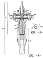
- FIG. 3 is a schematic cross section of the preferred spherical ball valve sliced through its y-axis.
- FIG. 4 is a schematic cross section of the preferred injector/valve combination.
- FIG. 5 is a diagram of the preferred coloring procedure utilizing the preferred injector/valve combination and the preferred spherical ball valve.
- the spherical ball valve 40 of FIG. 3 which may be made from stainless steel (preferably), titanium, carbon steel, and the like, comprises a first channel 42 which runs through the entire sphere on one single axis (the x-axis, for instance) and at a specific angle (such that the entire channel 42 is located at 0° on the x-axis).
- the ball valve 40 also comprises a second channel 44 which runs through the.
- the first channel 42 permits flow of the liquid colorant (not illustrated) through the valve 40 to a recirculation feed line ( 58 of FIG. 4 ) when aligned with the inlet feed line ( 52 of FIG. 4 ) from a storage tank ( 72 of FIG. 5 ).
- the first channel 42 is disengaged from all of its corresponding feed lines ( 52, 58 of FIG. 4 ) and permits the flow of liquid colorant (such as polymeric colorants, not illustrated) through the ball valve 40 ( 43 of FIG. 4 ) and into the dispensing feed line ( 64 of FIG. 4 ).
- the bore of each channel 42, 44 is the same for each; however, the actual size of both bores in said channels 42, 44 may be of any size as long as they are the size as the bore of the inlet feed line ( 52 of FIG.
- the ball valve 40 ( 43 of FIG. 4 ) size is merely dependent upon the amount of space between all of the feed lines ( 52, 58, 64 of FIG. 4 ) within the entire valve assembly ( 41 of FIG. 4 ).
- the dispensing feed line ( 64 of FIG. 4 ) permits the flow of the liquid colorant (not illustrated) into the injector ( 66 of FIG. 4 ) which itself possesses the same size bore as the ball valve 40 and the feed lines ( 52, 58, 64 of FIG. 4 ).
- valve assembly 41 may be attached to the valve assembly 41 by way of a screw mechanism (not illustrated), in which case a straight screw (not illustrated) is preferably and beneficially utilized in conjunction with a rubber gasket ( 68 of FIG. 4 ) thereto attached.
- the injector ( 66 of FIG. 4 ) may also be welded, or the like, to the valve assembly 41 as well.
- FIG. 5 thus incorporates the preferred injector/valve combination ( 70 of FIG. 4 ) into the entire slabstock foam coloring apparatus and procedure.
- the colorant is transported from a storage tank 72 to at least one positive displacement spur gear pump 74 coupled to a variable speed motor/drive 76 (such as available from Viking).
- the motor/pump combination 74, 76 is run continuously in either recirculation or dispense mode (depending on the position of the 3-way valve 78 ).
- the colorant flows through the injector 80 into a pre-mix manifold 82 .
- the throughput pressure is measured through the utilization of a pressure gauge 84 attached to the feed line 85 from the pump 74 to the 3-way valve 78 .
- the 3-way valve 78 is air actuated (although any other type of actuator may be used) and and directs the flow of colorant from the recirculation feed line 86 to the dispense feed line to the injector 80 ) when color flow to the manifold 82 is desired. From the manifold 82 , the colorant is moved to a mixing head 88 and then further on to color the target slabstock foam (not illustrated).
Landscapes
- Chemical & Material Sciences (AREA)
- Chemical Kinetics & Catalysis (AREA)
- Engineering & Computer Science (AREA)
- Mechanical Engineering (AREA)
- General Engineering & Computer Science (AREA)
- Casting Or Compression Moulding Of Plastics Or The Like (AREA)
- Processing And Handling Of Plastics And Other Materials For Molding In General (AREA)
- Taps Or Cocks (AREA)
- Nozzles (AREA)
- Luminescent Compositions (AREA)
- Investigating Or Analysing Materials By The Use Of Chemical Reactions (AREA)
- Catching Or Destruction (AREA)
- Telephone Function (AREA)
- Prostheses (AREA)
Applications Claiming Priority (2)
| Application Number | Priority Date | Filing Date | Title |
|---|---|---|---|
| US09/259,114 US6220296B1 (en) | 1999-02-26 | 1999-02-26 | Injector/valve combination designed to improve color dosing response time |
| US259114 | 2002-09-26 |
Publications (3)
| Publication Number | Publication Date |
|---|---|
| EP1031776A2 true EP1031776A2 (fr) | 2000-08-30 |
| EP1031776A3 EP1031776A3 (fr) | 2001-10-31 |
| EP1031776B1 EP1031776B1 (fr) | 2005-04-20 |
Family
ID=22983590
Family Applications (1)
| Application Number | Title | Priority Date | Filing Date |
|---|---|---|---|
| EP00301492A Expired - Lifetime EP1031776B1 (fr) | 1999-02-26 | 2000-02-25 | Combinaison buse d'injection/soupape pour améliorer le temps de réponse du dosage des couleurs |
Country Status (10)
| Country | Link |
|---|---|
| US (3) | US6220296B1 (fr) |
| EP (1) | EP1031776B1 (fr) |
| JP (1) | JP4647740B2 (fr) |
| CN (1) | CN1266962A (fr) |
| AT (1) | ATE293768T1 (fr) |
| AU (1) | AU757202B2 (fr) |
| BR (1) | BR0000945B1 (fr) |
| CA (1) | CA2299106A1 (fr) |
| DE (1) | DE60019480T2 (fr) |
| TW (1) | TW466314B (fr) |
Cited By (1)
| Publication number | Priority date | Publication date | Assignee | Title |
|---|---|---|---|---|
| WO2001089677A1 (fr) * | 2000-05-24 | 2001-11-29 | Milliken & Company | Ensemble doseur ameliore |
Families Citing this family (24)
| Publication number | Priority date | Publication date | Assignee | Title |
|---|---|---|---|---|
| FR2772367B1 (fr) * | 1997-12-11 | 2000-03-03 | Georges Ollier | Perfectionnements apportes a la realisation de melanges notamment pour la fabrication de boissons gazeuses |
| US6895708B2 (en) * | 2003-05-29 | 2005-05-24 | Surefire, Llc | Accessory mounts for firearms |
| SE0302385D0 (sv) * | 2003-09-08 | 2003-09-08 | John Henrik Guy Welin-Berger | Tändremsa för snabbstart av brasor, eldstäder etc |
| US20050133958A1 (en) * | 2003-12-22 | 2005-06-23 | Lear Corporation | System and method for coloring a spray urethane skin for vehicle interior trim components and skins made thereby |
| US20060024507A1 (en) * | 2004-07-29 | 2006-02-02 | Lear Corporation | Method for preparing a spray urethane skin having a clear coat for vehicle interior trim components and skins made thereby |
| RU2332605C2 (ru) * | 2004-08-19 | 2008-08-27 | Вальвулас Арко, С.Л. | Трехходовой клапан с независимыми четвертьоборотными выпускными отверстиями |
| US20060071358A1 (en) * | 2004-10-04 | 2006-04-06 | Lear Corporation | Apparatus and method for delivering polyurethane forming methods |
| ATE360137T1 (de) * | 2004-12-30 | 2007-05-15 | Grundfos Management As | Dosierpumpenaggregat |
| DE502004010210D1 (de) * | 2004-12-30 | 2009-11-19 | Grundfos Nonox As | Dosierpumpenaggregat |
| DE502004005576D1 (de) * | 2004-12-30 | 2008-01-03 | Grundfos Nonox As | Vorrichtung zur Erzeugung eines Reduktionsmittel-Luft-Gemisches |
| JP4563226B2 (ja) * | 2005-03-17 | 2010-10-13 | 日本碍子株式会社 | セラミック成形体の製造方法及び着色セラミック成形体 |
| US8550690B2 (en) * | 2007-04-13 | 2013-10-08 | Construction Research & Technology Gmbh | Method and device for dispensing liquids |
| US8678031B2 (en) * | 2011-06-01 | 2014-03-25 | Institute Of Nuclear Energy Research, Atomic Energy Council | Pipe-passivating alkali-injecting device for a nuclear plant |
| CN103968106B (zh) * | 2013-02-05 | 2016-08-10 | 沈如华 | 调色机及其换向阀装置 |
| GB2518447C (en) * | 2013-09-24 | 2021-10-20 | Htc Man Services Limited | Apparatus for delivering material to a pipe |
| US11821047B2 (en) | 2017-02-16 | 2023-11-21 | Apalta Patent OÜ | High pressure zone formation for pretreatment |
| KR102069688B1 (ko) * | 2017-11-24 | 2020-01-23 | 최주환 | 내부는 다수의 공극이 형성되어 탄성을 가지며 외부는 밀집한 구조로 형성되어 내부 보다 상대적으로 높은 경도를 갖는 물품을 제조하는 데에 적합한 신규한 우레탄 발포 공정 |
| CN110354362A (zh) * | 2019-08-12 | 2019-10-22 | 杨豪 | 可控浓度的镇痛泵及其镇痛泵的控制方法 |
| US11504678B2 (en) * | 2019-09-10 | 2022-11-22 | Bradley Philip Doane | Self-contained fire protection system |
| BR112022012348A2 (pt) | 2019-12-22 | 2022-09-13 | Sweetwater Energy Inc | Métodos de fazer lignina especializada e produtos de lignina da biomassa |
| WO2022072873A1 (fr) | 2020-10-02 | 2022-04-07 | Sweetwater Energy, Inc. | Système d'injecteur pour équipement d'extrusion |
| EP4245406A1 (fr) * | 2022-03-17 | 2023-09-20 | Saravanos Process++ SRL | Systèmes et procédés d'alimentation de matériaux d'entrée dans un système de traitement |
| CN115366238B (zh) * | 2022-10-01 | 2023-06-02 | 佛山蓝动力智能科技有限公司 | 一种数码施釉机 |
| CN121083885B (zh) * | 2025-11-09 | 2026-02-10 | 江苏宝翼通讯科技有限公司 | 基于分配阀的光缆套塑换色进料装置 |
Citations (1)
| Publication number | Priority date | Publication date | Assignee | Title |
|---|---|---|---|---|
| US4284279A (en) | 1979-02-21 | 1981-08-18 | Sony Corporation | Phonograph record player |
Family Cites Families (18)
| Publication number | Priority date | Publication date | Assignee | Title |
|---|---|---|---|---|
| US308519A (en) * | 1884-11-25 | Caspee pfaudlee | ||
| US3684241A (en) * | 1970-08-31 | 1972-08-15 | Stile Craft Mfg Inc | Ball valve |
| JPS5217854Y2 (fr) * | 1971-05-28 | 1977-04-22 | ||
| US3857550A (en) | 1972-04-20 | 1974-12-31 | Bayer Ag | Machine for producing foams, homogeneous or structural materials from at least two liquid reaction components |
| US4223811A (en) * | 1975-12-15 | 1980-09-23 | Imre Czegledi | Fluid metering, mixing and dispensing machine |
| JPS54117944A (en) * | 1978-03-06 | 1979-09-13 | Nippon Reguri Kk | Opening and shutting valve |
| JPS56101265A (en) * | 1980-01-17 | 1981-08-13 | Sanyo Electric Co Ltd | Electronic type cash register |
| US4284729A (en) | 1980-03-31 | 1981-08-18 | Milliken Research Corporation | Process for coloring thermosetting resins |
| US4326560A (en) * | 1980-10-06 | 1982-04-27 | R.F.I. Inc. | Apparatus for injecting fluids into aggregates |
| JPS5913170A (ja) * | 1982-07-14 | 1984-01-23 | Tlv Co Ltd | 多方向ボ−ル弁 |
| JPS62162471A (ja) * | 1986-01-09 | 1987-07-18 | Osaka Daiyamondo Kogyo Kk | 研削装置 |
| JPH0623802Y2 (ja) * | 1986-07-17 | 1994-06-22 | 株式会社ナブコ | 鉄道車両用ボールコック |
| US4778083A (en) * | 1987-08-10 | 1988-10-18 | Decker Herman W | Mixing and dispensing apparatus |
| US4915133A (en) * | 1989-03-15 | 1990-04-10 | Harrison C L Scott | Valve device for piping systems |
| US5998220A (en) * | 1991-05-29 | 1999-12-07 | Beckman Coulter, Inc. | Opposable-element assay devices, kits, and methods employing them |
| GB9312843D0 (en) | 1993-06-22 | 1993-08-04 | Spirax Sarco Ltd | Condensate traps |
| US5613639A (en) * | 1995-08-14 | 1997-03-25 | Storm; Karl | On/off control valve for a shower head |
| JPH09280390A (ja) * | 1996-04-12 | 1997-10-28 | Asahi Organic Chem Ind Co Ltd | 三方ボールバルブ |
-
1999
- 1999-02-26 US US09/259,114 patent/US6220296B1/en not_active Expired - Lifetime
-
2000
- 2000-02-22 CA CA002299106A patent/CA2299106A1/fr not_active Abandoned
- 2000-02-23 AU AU19419/00A patent/AU757202B2/en not_active Expired
- 2000-02-24 BR BRPI0000945-8A patent/BR0000945B1/pt active IP Right Grant
- 2000-02-25 TW TW089103393A patent/TW466314B/zh not_active IP Right Cessation
- 2000-02-25 EP EP00301492A patent/EP1031776B1/fr not_active Expired - Lifetime
- 2000-02-25 AT AT00301492T patent/ATE293768T1/de not_active IP Right Cessation
- 2000-02-25 DE DE60019480T patent/DE60019480T2/de not_active Expired - Lifetime
- 2000-02-25 CN CN00106414A patent/CN1266962A/zh active Pending
- 2000-02-28 JP JP2000051930A patent/JP4647740B2/ja not_active Expired - Lifetime
- 2000-06-29 US US09/606,261 patent/US6316053B1/en not_active Expired - Fee Related
- 2000-08-01 US US09/629,347 patent/US6345646B1/en not_active Expired - Fee Related
Patent Citations (1)
| Publication number | Priority date | Publication date | Assignee | Title |
|---|---|---|---|---|
| US4284279A (en) | 1979-02-21 | 1981-08-18 | Sony Corporation | Phonograph record player |
Cited By (2)
| Publication number | Priority date | Publication date | Assignee | Title |
|---|---|---|---|---|
| WO2001089677A1 (fr) * | 2000-05-24 | 2001-11-29 | Milliken & Company | Ensemble doseur ameliore |
| US6378734B1 (en) | 2000-05-24 | 2002-04-30 | Milliken & Company | Dosing assembly |
Also Published As
| Publication number | Publication date |
|---|---|
| BR0000945A (pt) | 2000-10-31 |
| JP4647740B2 (ja) | 2011-03-09 |
| CA2299106A1 (fr) | 2000-08-26 |
| ATE293768T1 (de) | 2005-05-15 |
| DE60019480D1 (de) | 2005-05-25 |
| US6316053B1 (en) | 2001-11-13 |
| CN1266962A (zh) | 2000-09-20 |
| EP1031776A3 (fr) | 2001-10-31 |
| DE60019480T2 (de) | 2006-02-23 |
| JP2000249236A (ja) | 2000-09-12 |
| AU757202B2 (en) | 2003-02-06 |
| EP1031776B1 (fr) | 2005-04-20 |
| TW466314B (en) | 2001-12-01 |
| US6345646B1 (en) | 2002-02-12 |
| US6220296B1 (en) | 2001-04-24 |
| AU1941900A (en) | 2000-08-31 |
| BR0000945B1 (pt) | 2013-06-04 |
Similar Documents
| Publication | Publication Date | Title |
|---|---|---|
| US6220296B1 (en) | Injector/valve combination designed to improve color dosing response time | |
| US6247839B1 (en) | Valve disposition and configuration designed to improve color dosing response time in a process of coloring polyurethane foam carpet underlay | |
| AU2001247913B2 (en) | Improved dosing assembly | |
| AU2001247913A1 (en) | Improved dosing assembly | |
| US6079867A (en) | Self-cleaning, mixing apparatus and method for the production of polyurethane formulations | |
| US7455446B2 (en) | Co-injection mixing method and apparatus | |
| US5587182A (en) | Apparatus for the production of endless polyurethane moldings | |
| GB2488125A (en) | Injection Apparatus | |
| CA2107240C (fr) | Methode et dispositif pour preparer un melange de reaction a base de polyurethane | |
| KR200311877Y1 (ko) | 인조대리석 원료의 제조장치 | |
| JPS62255108A (ja) | 射出成形機 | |
| US20060054659A1 (en) | Method and apparatus for blending a colorant | |
| KR20020090975A (ko) | 개폐수단이 구비된 주입노즐이 결합된 폴리우레탄믹싱헤드 어셈브리 |
Legal Events
| Date | Code | Title | Description |
|---|---|---|---|
| PUAI | Public reference made under article 153(3) epc to a published international application that has entered the european phase |
Free format text: ORIGINAL CODE: 0009012 |
|
| AK | Designated contracting states |
Kind code of ref document: A2 Designated state(s): AT BE CH CY DE DK ES FI FR GB GR IE IT LI LU MC NL PT SE |
|
| AX | Request for extension of the european patent |
Free format text: AL;LT;LV;MK;RO;SI |
|
| PUAL | Search report despatched |
Free format text: ORIGINAL CODE: 0009013 |
|
| AK | Designated contracting states |
Kind code of ref document: A3 Designated state(s): AT BE CH CY DE DK ES FI FR GB GR IE IT LI LU MC NL PT SE |
|
| AX | Request for extension of the european patent |
Free format text: AL;LT;LV;MK;RO;SI |
|
| RIC1 | Information provided on ipc code assigned before grant |
Free format text: 7F 16K 5/06 A, 7B 29C 45/18 B, 7F 16K 11/087 B |
|
| 17P | Request for examination filed |
Effective date: 20020327 |
|
| AKX | Designation fees paid |
Free format text: AT BE CH CY DE DK ES FI FR GB GR IE IT LI LU MC NL PT SE |
|
| 17Q | First examination report despatched |
Effective date: 20031205 |
|
| GRAP | Despatch of communication of intention to grant a patent |
Free format text: ORIGINAL CODE: EPIDOSNIGR1 |
|
| GRAS | Grant fee paid |
Free format text: ORIGINAL CODE: EPIDOSNIGR3 |
|
| GRAA | (expected) grant |
Free format text: ORIGINAL CODE: 0009210 |
|
| RBV | Designated contracting states (corrected) |
Designated state(s): AT BE CH CY DE DK ES FI FR GB GR IT LI NL PT SE |
|
| AK | Designated contracting states |
Kind code of ref document: B1 Designated state(s): AT BE CH CY DE DK ES FI FR GB GR IT LI NL PT SE |
|
| PG25 | Lapsed in a contracting state [announced via postgrant information from national office to epo] |
Ref country code: CH Free format text: LAPSE BECAUSE OF FAILURE TO SUBMIT A TRANSLATION OF THE DESCRIPTION OR TO PAY THE FEE WITHIN THE PRESCRIBED TIME-LIMIT Effective date: 20050420 Ref country code: LI Free format text: LAPSE BECAUSE OF FAILURE TO SUBMIT A TRANSLATION OF THE DESCRIPTION OR TO PAY THE FEE WITHIN THE PRESCRIBED TIME-LIMIT Effective date: 20050420 Ref country code: AT Free format text: LAPSE BECAUSE OF FAILURE TO SUBMIT A TRANSLATION OF THE DESCRIPTION OR TO PAY THE FEE WITHIN THE PRESCRIBED TIME-LIMIT Effective date: 20050420 Ref country code: FI Free format text: LAPSE BECAUSE OF FAILURE TO SUBMIT A TRANSLATION OF THE DESCRIPTION OR TO PAY THE FEE WITHIN THE PRESCRIBED TIME-LIMIT Effective date: 20050420 |
|
| REG | Reference to a national code |
Ref country code: GB Ref legal event code: FG4D |
|
| REG | Reference to a national code |
Ref country code: CH Ref legal event code: EP |
|
| REG | Reference to a national code |
Ref country code: IE Ref legal event code: FG4D |
|
| REF | Corresponds to: |
Ref document number: 60019480 Country of ref document: DE Date of ref document: 20050525 Kind code of ref document: P |
|
| PG25 | Lapsed in a contracting state [announced via postgrant information from national office to epo] |
Ref country code: SE Free format text: LAPSE BECAUSE OF FAILURE TO SUBMIT A TRANSLATION OF THE DESCRIPTION OR TO PAY THE FEE WITHIN THE PRESCRIBED TIME-LIMIT Effective date: 20050720 Ref country code: DK Free format text: LAPSE BECAUSE OF FAILURE TO SUBMIT A TRANSLATION OF THE DESCRIPTION OR TO PAY THE FEE WITHIN THE PRESCRIBED TIME-LIMIT Effective date: 20050720 Ref country code: GR Free format text: LAPSE BECAUSE OF FAILURE TO SUBMIT A TRANSLATION OF THE DESCRIPTION OR TO PAY THE FEE WITHIN THE PRESCRIBED TIME-LIMIT Effective date: 20050720 |
|
| PG25 | Lapsed in a contracting state [announced via postgrant information from national office to epo] |
Ref country code: ES Free format text: LAPSE BECAUSE OF FAILURE TO SUBMIT A TRANSLATION OF THE DESCRIPTION OR TO PAY THE FEE WITHIN THE PRESCRIBED TIME-LIMIT Effective date: 20050731 |
|
| PG25 | Lapsed in a contracting state [announced via postgrant information from national office to epo] |
Ref country code: PT Free format text: LAPSE BECAUSE OF FAILURE TO SUBMIT A TRANSLATION OF THE DESCRIPTION OR TO PAY THE FEE WITHIN THE PRESCRIBED TIME-LIMIT Effective date: 20050920 |
|
| REG | Reference to a national code |
Ref country code: CH Ref legal event code: PL |
|
| PGFP | Annual fee paid to national office [announced via postgrant information from national office to epo] |
Ref country code: NL Payment date: 20060129 Year of fee payment: 7 |
|
| PLBE | No opposition filed within time limit |
Free format text: ORIGINAL CODE: 0009261 |
|
| STAA | Information on the status of an ep patent application or granted ep patent |
Free format text: STATUS: NO OPPOSITION FILED WITHIN TIME LIMIT |
|
| ET | Fr: translation filed | ||
| 26N | No opposition filed |
Effective date: 20060123 |
|
| NLV4 | Nl: lapsed or anulled due to non-payment of the annual fee |
Effective date: 20070901 |
|
| PG25 | Lapsed in a contracting state [announced via postgrant information from national office to epo] |
Ref country code: NL Free format text: LAPSE BECAUSE OF NON-PAYMENT OF DUE FEES Effective date: 20070901 |
|
| PG25 | Lapsed in a contracting state [announced via postgrant information from national office to epo] |
Ref country code: CY Free format text: LAPSE BECAUSE OF FAILURE TO SUBMIT A TRANSLATION OF THE DESCRIPTION OR TO PAY THE FEE WITHIN THE PRESCRIBED TIME-LIMIT Effective date: 20050420 |
|
| PGFP | Annual fee paid to national office [announced via postgrant information from national office to epo] |
Ref country code: IT Payment date: 20090225 Year of fee payment: 10 |
|
| PGFP | Annual fee paid to national office [announced via postgrant information from national office to epo] |
Ref country code: BE Payment date: 20090408 Year of fee payment: 10 |
|
| BERE | Be: lapsed |
Owner name: *MILLIKEN & CY Effective date: 20100228 |
|
| PG25 | Lapsed in a contracting state [announced via postgrant information from national office to epo] |
Ref country code: BE Free format text: LAPSE BECAUSE OF NON-PAYMENT OF DUE FEES Effective date: 20100228 |
|
| PG25 | Lapsed in a contracting state [announced via postgrant information from national office to epo] |
Ref country code: IT Free format text: LAPSE BECAUSE OF NON-PAYMENT OF DUE FEES Effective date: 20100225 |
|
| REG | Reference to a national code |
Ref country code: FR Ref legal event code: PLFP Year of fee payment: 17 |
|
| REG | Reference to a national code |
Ref country code: FR Ref legal event code: PLFP Year of fee payment: 18 |
|
| REG | Reference to a national code |
Ref country code: FR Ref legal event code: PLFP Year of fee payment: 19 |
|
| PGFP | Annual fee paid to national office [announced via postgrant information from national office to epo] |
Ref country code: GB Payment date: 20190227 Year of fee payment: 20 Ref country code: DE Payment date: 20190227 Year of fee payment: 20 |
|
| PGFP | Annual fee paid to national office [announced via postgrant information from national office to epo] |
Ref country code: FR Payment date: 20190225 Year of fee payment: 20 |
|
| REG | Reference to a national code |
Ref country code: DE Ref legal event code: R071 Ref document number: 60019480 Country of ref document: DE |
|
| REG | Reference to a national code |
Ref country code: GB Ref legal event code: PE20 Expiry date: 20200224 |
|
| PG25 | Lapsed in a contracting state [announced via postgrant information from national office to epo] |
Ref country code: GB Free format text: LAPSE BECAUSE OF EXPIRATION OF PROTECTION Effective date: 20200224 |