EP1031777B1 - Ensemble à clapet et dispositif de circulation et de distribution de fluide comprenant un tel ensemble - Google Patents
Ensemble à clapet et dispositif de circulation et de distribution de fluide comprenant un tel ensemble Download PDFInfo
- Publication number
- EP1031777B1 EP1031777B1 EP00440047A EP00440047A EP1031777B1 EP 1031777 B1 EP1031777 B1 EP 1031777B1 EP 00440047 A EP00440047 A EP 00440047A EP 00440047 A EP00440047 A EP 00440047A EP 1031777 B1 EP1031777 B1 EP 1031777B1
- Authority
- EP
- European Patent Office
- Prior art keywords
- valve body
- duct
- valve
- ducts
- portions
- Prior art date
- Legal status (The legal status is an assumption and is not a legal conclusion. Google has not performed a legal analysis and makes no representation as to the accuracy of the status listed.)
- Expired - Lifetime
Links
- 239000012530 fluid Substances 0.000 title claims abstract description 43
- 238000009826 distribution Methods 0.000 title claims abstract description 17
- 238000011144 upstream manufacturing Methods 0.000 claims description 14
- 230000000295 complement effect Effects 0.000 claims description 5
- 230000000694 effects Effects 0.000 claims 1
- 238000000926 separation method Methods 0.000 claims 1
- 230000007423 decrease Effects 0.000 abstract 1
- 240000008042 Zea mays Species 0.000 description 2
- 230000000712 assembly Effects 0.000 description 2
- 238000000429 assembly Methods 0.000 description 2
- 238000001816 cooling Methods 0.000 description 2
- 239000007788 liquid Substances 0.000 description 2
- 230000002093 peripheral effect Effects 0.000 description 2
- 230000001154 acute effect Effects 0.000 description 1
- 238000004026 adhesive bonding Methods 0.000 description 1
- 238000002485 combustion reaction Methods 0.000 description 1
- 238000010276 construction Methods 0.000 description 1
- 238000005520 cutting process Methods 0.000 description 1
- 238000009795 derivation Methods 0.000 description 1
- 230000006866 deterioration Effects 0.000 description 1
- 238000010586 diagram Methods 0.000 description 1
- 230000010339 dilation Effects 0.000 description 1
- 238000005485 electric heating Methods 0.000 description 1
- 239000000446 fuel Substances 0.000 description 1
- 238000010438 heat treatment Methods 0.000 description 1
- 238000009776 industrial production Methods 0.000 description 1
- 238000009434 installation Methods 0.000 description 1
- 230000007257 malfunction Effects 0.000 description 1
- 238000005259 measurement Methods 0.000 description 1
- 239000002184 metal Substances 0.000 description 1
- 238000012986 modification Methods 0.000 description 1
- 230000004048 modification Effects 0.000 description 1
- 210000000056 organ Anatomy 0.000 description 1
- 238000005192 partition Methods 0.000 description 1
- 238000011084 recovery Methods 0.000 description 1
- 238000006467 substitution reaction Methods 0.000 description 1
- 229920001169 thermoplastic Polymers 0.000 description 1
- 239000004416 thermosoftening plastic Substances 0.000 description 1
- 238000003466 welding Methods 0.000 description 1
Images


Classifications
-
- F—MECHANICAL ENGINEERING; LIGHTING; HEATING; WEAPONS; BLASTING
- F16—ENGINEERING ELEMENTS AND UNITS; GENERAL MEASURES FOR PRODUCING AND MAINTAINING EFFECTIVE FUNCTIONING OF MACHINES OR INSTALLATIONS; THERMAL INSULATION IN GENERAL
- F16K—VALVES; TAPS; COCKS; ACTUATING-FLOATS; DEVICES FOR VENTING OR AERATING
- F16K11/00—Multiple-way valves, e.g. mixing valves; Pipe fittings incorporating such valves
- F16K11/02—Multiple-way valves, e.g. mixing valves; Pipe fittings incorporating such valves with all movable sealing faces moving as one unit
- F16K11/04—Multiple-way valves, e.g. mixing valves; Pipe fittings incorporating such valves with all movable sealing faces moving as one unit comprising only lift valves
- F16K11/052—Multiple-way valves, e.g. mixing valves; Pipe fittings incorporating such valves with all movable sealing faces moving as one unit comprising only lift valves with pivoted closure members, e.g. butterfly valves
- F16K11/0525—Multiple-way valves, e.g. mixing valves; Pipe fittings incorporating such valves with all movable sealing faces moving as one unit comprising only lift valves with pivoted closure members, e.g. butterfly valves the closure members being pivoted around an essentially central axis
-
- Y—GENERAL TAGGING OF NEW TECHNOLOGICAL DEVELOPMENTS; GENERAL TAGGING OF CROSS-SECTIONAL TECHNOLOGIES SPANNING OVER SEVERAL SECTIONS OF THE IPC; TECHNICAL SUBJECTS COVERED BY FORMER USPC CROSS-REFERENCE ART COLLECTIONS [XRACs] AND DIGESTS
- Y10—TECHNICAL SUBJECTS COVERED BY FORMER USPC
- Y10T—TECHNICAL SUBJECTS COVERED BY FORMER US CLASSIFICATION
- Y10T137/00—Fluid handling
- Y10T137/8593—Systems
- Y10T137/86493—Multi-way valve unit
- Y10T137/86863—Rotary valve unit
-
- Y—GENERAL TAGGING OF NEW TECHNOLOGICAL DEVELOPMENTS; GENERAL TAGGING OF CROSS-SECTIONAL TECHNOLOGIES SPANNING OVER SEVERAL SECTIONS OF THE IPC; TECHNICAL SUBJECTS COVERED BY FORMER USPC CROSS-REFERENCE ART COLLECTIONS [XRACs] AND DIGESTS
- Y10—TECHNICAL SUBJECTS COVERED BY FORMER USPC
- Y10T—TECHNICAL SUBJECTS COVERED BY FORMER US CLASSIFICATION
- Y10T137/00—Fluid handling
- Y10T137/8593—Systems
- Y10T137/877—With flow control means for branched passages
- Y10T137/87788—With valve or movable deflector at junction
- Y10T137/87812—Pivoted valve or deflector
Definitions
- the present invention relates to the field of piloting the circulation of fluids through networks and circuits formed of conduits, tubular or not, interconnected and connected to each other, and relates to a valve assembly or valve dispensing and / or shutter, and a device for circulating and distributing fluid (s) comprising such a set valve.
- the construction, structure and installation of the flaps are such that they substantially disturb the flow of fluids, which their positioning, and thereby systematically generate a loss of noticeable load, even in the erased position allowing the free passage of the flow of fluid.
- valves and their control devices have complex constitutions, require assembly operations and tedious assemblies and are directly and frontally exposed to thrust of fluid flow, which generates significant pressures on the valve body and accelerates their wear and deterioration of the tightness to the obtaining.
- DE-A-36 12 672 and CH-A-483974 disclose a valve assembly according to features of the preamble of claim 1.
- the present invention aims to further simplify operations assembly with respect to the flap assemblies currently known and, moreover, of improve the seal between the valve body and the inner walls of the duct (s).
- the present invention relates to a valve assembly according to the claim 1.
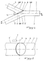
- valve assembly (or valve) dispensing or shutter is intended for controlling the passage of at least one fluid flow 1, 1 'between at least one duct upstream or primary 2, 2 'and at least one downstream or secondary duct 3, 3' and comprises a mobile valve body 4 forming a dispensing member and / or shutter.
- the valve body 4 forms, in at least one of its extreme positions, part of the wall of the portion or portions intermediate duct (s) 5, 5 'connecting said at least one upstream duct or primary 2, 2 'auditing at least one downstream or secondary duct 3, 3'.
- the axis of rotation 6 carrying the body of the valve 4 is mounted by being offset laterally with respect to the AM axis or axes of the possible travel path (s) for the or the streams of fluid (s) 1, 1 ', in particular in the downstream or secondary ducts 3, 3 '.
- valve body 4 forms part of the or portion (s) of conduit (s) intermediate (s) 5, 5 'in each of its positions extremes, which makes it possible to reduce the pressure losses of the fluid flow in the two positions normally occupied by the valve body 4.
- the face of the valve body 4 exposed to the flow of fluid 1, 1 ' is, whatever the position end taken by said valve body, attacked by said flow at an acute angle (as illustrated by the angle between the relevant surface of said valve body 4 and the axis median AM of the fluid path 1, 1 'in the corresponding upstream pipe 2, 2'). he this results in a low pressure on said valve body 4, the latter realizing more a deviation of the fluid flow 1, 1 ', than an obstruction of the passage to condemn.
- the control device 7 of the valve is located outside the fluid flow (s) 1, 1 ' in the primary (s) 2, 2 'and secondary (3) 3' conduits, the positioning of said valve body 4 being determined, if appropriate, according to at least one physicochemical parameter of the fluid (s) 1, 1 ', such as, for example, the temperature, measured in a bypass or secondary circulation circuit 17, fed by a primary conduit 2, 2 'or secondary 3, 3' or connecting two of these last.
- the control device 7 ensuring the steering of the assembly to valve or valve dispensing and / or shutter can thus include a thermostat thermally controlled by a flow of fluid present in a circuit secondary, separated from the circuit formed by the primary conduits 2, 2 'and secondary 3, 3 'or disposed in derivation relative thereto.
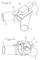
- control of the valve assembly or of the valve may alternatively also be realized by a controlled thermostat, for example a heating controlled, user-friendly, wax cartridge, allowing the dilation of the latter and the recovery of the resulting motion for the actuation of the valve body 4 via the axis of rotation 6 (see particularly Figures 7 and 10 of the accompanying drawings).
- a controlled thermostat for example a heating controlled, user-friendly, wax cartridge
- control of the valve assembly or the valve can also be achieved by controlled mechanical actuation or by motorization such as a torque motor, a DC motor or a step-by-step engine.
- This calibrated leak is obtained by defining a gap of determined passage 4 'between the edge of the body of the valve 4 and said support zone or complementary shape of the inner wall of the intermediate duct portions 5, 5 '.
- This gap can be formed by making a deformation at the level of the corresponding zone (s) of said inner wall and / or altering a part of the less than the outer edge of the valve body 4.
- the calibrated leak can also be obtained by providing one or more openings of defined shape and size in the valve body 4 itself, which makes it possible in particular to obtain leakage of identical importance in the two extreme positions of the said body of valve 4.
- the practical embodiment of the calibrated leak shall, as far as possible, do not cause disturbance in the flow of the fluid 1, 1 'next the authorized route.
- valve body 4 and the axis of rotation 6 are made in the form of an element or body to be inserted 11 and are, where appropriate, integrated into an insert 11 '(also called cassette) forming also the internal walls of the portion (s) of conduit (s) intermediate (s) 5, 5 ', in particular the bearing zones 8, 8' of the valve body 4 in its positions extremes or areas of internal walls 9, 9 'of complementary shape, said element or said insert 11 being mounted by interlocking in a cutting or a cavity 12 of corresponding shape in a zone of connecting said at least one primary conduit 2, 2 'with said at least one secondary duct 3, 3 '(see FIGS. 4 to 9).
- FIGS 1 to 6 of the accompanying drawings show schematically, by way of non-limiting examples, three cases of practical application of the invention, corresponding in fact to three embodiments of the latter, namely, of a an application as a shutter member in a two-way system (an input and an output path), shown in Figure 6 of the drawings annexed, on the other hand, an application as a distribution / closure in a three-way system (one input channel and two output channels), represented Figures 1 to 3 and 7 to 12 of the accompanying drawings and, finally, an application as a distribution organ in a four-lane system (two input and two two output channels), shown in Figures 4 and 5 of the accompanying drawings.
- valve body 4 constitutes with the body 11 "of the insert 11 'or the walls of the duct portions intermediate 5, 5 ', a shutter valve and / or distribution integrated into the convergence zone of primary conduits 2, 2 'and secondary 3, 3'.
- valve assembly realizes only a function of the type opening / closing of passage between a portion upstream duct 2 and a downstream duct portion 3.
- valve body 4 freely passes the fluid 1 with a loss minimum load and, in its deployed position, said valve body 4 obstructs the passage and prevents any flow of fluid 1.
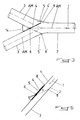
- the assembly valve makes it possible to direct the flow of fluid 1 flowing in the primary conduit 2 to one of the two secondary ducts 3 or 3 ', completely obstructing (or with a calibrated leak) the inlet to the other of said secondary ducts 3 or 3 ', while generating a minimal pressure drop.
- valve body portion 4 extending in the upstream direction of the axis of rotation 6 can be advantageously larger than the valve body portion 4 extending downstream, preferably with a ratio of about 2: 1, said valve body 4 being advantageously, in particular in a system with three channels with a Y structure, aligned with the central axis AM of the fluid stream 1, 1 ' in the primary pipe 2, 2 'in the intermediate open position.
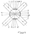
- valve body 4 can advantageously be present in the form of a dividing wall delimiting, where appropriate in cooperation with two portions of opposite walls 9, 9 'or 13, 13' located on the and on the other side of said valve body 4, two portions of paths or ducts intermediate and 5 'each connecting an upstream duct 2, 2' and a downstream duct 3, 3 'between them, the rotation of said valve body 4 from one extreme position to the other to reverse the connections between the upstream pipes 2, 2 'and downstream 3, 3'.
- the body of valve 4 and the two opposite wall portions 13, 13 'preferentially integral part of a body 11 mounted rotatably, in the manner of a ball, conical or cylindrical, at the level of the area of the node of convergence 14 upstream ducts 2, 2 'and downstream 3, 3', the valve body 4 forming in cross section a doubly convex wall and the wall portions 13, 13 'having a convex conformation directed towards the convex recesses respective opposites of said valve body 4.
- valve body 4 is eccentric with respect to the possible paths for the fluid streams 1 and 1 'and makes partition wall of both circuits and side wall elements for each of the intermediate pipe portions 5 and 5 '.
- By simple 90 ° rotation it is possible to simultaneously perform two connection reversals in to change from a 1-3 / 1'-3 'circulation scheme to a diagram of 1-3 'circulation / 1'-3.
- valve or valve assembly is advantageously constituted of Thermoplastic components (except steering gear) assembled together by welding, screwing or gluing.
- Thermoplastic components except steering gear
- the mobile and functional components can also be made of metal parts, welded or screwed between they.
- Another subject of the present invention is a device for circulation and distribution of fluid (s) 1, 1 'between at least one primary conduit 2, 2 'and at least one secondary conduit 3, 3'.
- This distribution circulation device is mainly constituted, on the one hand, by a piece 15 in one piece, formed by the assembly converging and communicating several tubular conduits 2, 2 ', 3, 3' or several portions of tubular ducts connected to ducts 2, 2 ', 3, 3', particular in the form of Y (three-way system) or X (four-way system) channels), and having a cutout or an access opening 12 at the level of the zone the convergence node 14 of the primary (s) 2, 2 'and secondary (3) 3' and, on the other hand, by a valve assembly or a valve as described previously, including the valve body 4 or the shutter member and / or analogous distribution and the axis of rotation 6 at least are put in place in said zone of the convergence node 14 through the access opening 12, the latter being sealed by a lid or stopper 16 corresponding.
- the axis of rotation 6 passes through the cover or closure cap 16 of the access opening 12, the latter carrying at least a portion of the actuating mechanism 7 'forming a component of the control device 7 of the valve.
- the closure cover 16 may possibly be made integrally with the structural body 11 "of the insert 11 'and with at least one element support 18 for at least part of the piloting device 7. Watertightness can then be performed by surface contact between border areas peripherals of the opening 12 and the cover 16 forming a support platform ( Figures 9 and 10).
- valve assembly comprises a part to insert 11 '
- fluid tightness 1, 1 'at the convergence zone can be easily optimized by the realization of a pre-assembly structural body 11 '/ valve body 4 and axis of rotation 6, the peripheral contacts of which components in the extreme positions can be finely adjusted and will not be affected by the mounting of said insert 11 'in said part 15.
- the clamshell assembly and the circulation and dispensing device described above are particularly well suited for application in the cooling circuit of a motor vehicle with a combustion engine, but also for applications in the circulation circuits of air, fuel, washer fluid and exhaust gas from such vehicles.
Landscapes
- General Engineering & Computer Science (AREA)
- Engineering & Computer Science (AREA)
- Mechanical Engineering (AREA)
- Multiple-Way Valves (AREA)
- Lift Valve (AREA)
- Air Bags (AREA)
- Orthopedics, Nursing, And Contraception (AREA)
- Valve Housings (AREA)
- Physical Or Chemical Processes And Apparatus (AREA)
- Taps Or Cocks (AREA)
- Infusion, Injection, And Reservoir Apparatuses (AREA)
- Devices For Dispensing Beverages (AREA)
- Reciprocating Pumps (AREA)
- Sliding Valves (AREA)
Description
Claims (9)
- Ensemble à clapet ou vanne de distribution ou d'obturation, destiné(e) à contrôler le passage d'au moins un flux de fluide entre au moins un conduit amont ou primaire et au moins un conduit aval ou secondaire et comprenant un corps de clapet mobile formant organe de distribution et/ou d'obturation, caractérisé en ce que le corps de clapet (4) forme, dans au moins une de ses positions extrêmes, une partie de la paroi de la ou des portion(s) de conduit(s) intermédiaire(s) (5, 5') reliant ledit au moins un conduit amont ou primaire (2, 2') audit au moins un conduit aval ou secondaire (3, 3'), l'axe de rotation (6) portant le corps du clapet (4) étant déporté latéralement par rapport à l'axe ou aux axes médians (AM) du ou des trajet(s) de circulation possibles pour le ou les flux de fluide(s) (1, 1'), notamment dans les conduits aval ou secondaires (3, 3'), le corps de clapet (4) formant une partie de la ou des portion(s) de conduit(s) intermédiaire(s) (5, 5') dans chacune de ses positions extrêmes, caractérisé en ce que le corps de clapet (4) et l'axe de rotation (6) sont réalisés sous la forme d'un élément ou corps à insérer (11) et sont, le cas échéant, intégrés dans une pièce à insérer (11') formant également les parois internes de la ou des portion(s) de conduit(s) intermédiaire(s) (5, 5'), en particulier les zones d'appui (8, 8') du corps de clapet (4) dans ses positions extrêmes ou les zones de parois internes (9, 9') de forme complémentaire, ledit élément ou ladite pièce à insérer (11) étant monté(e) par emboítement dans une découpe ou une cavité (12) de forme correspondante ménagée dans une zone de raccordement dudit au moins un conduit primaire (2, 2') avec ledit au moins un conduit secondaire (3, 3')..
- Ensemble à clapet selon la revendication 1, caractérisé en ce que le dispositif de commande (7) du clapet est situé hors du ou des flux de fluide(s) (1, 1') dans les conduits primaire(s) (2, 2') et secondaire(s) (3, 3'), le positionnement dudit corps de clapet (4) étant déterminé, le cas échéant, en fonction d'au moins un paramètre physico-chimique du ou des fluides (1, 1'), tel que par exemple la température, mesuré dans un circuit de dérivation ou de circulation secondaire, alimenté par un conduit primaire (2, 2') ou secondaire (3, 3') ou reliant deux de ces derniers.
- Ensemble à clapet selon la revendication 1 ou 2, caractérisé en ce que le corps de clapet (4) et une partie au moins de la ou des zone(s) d'appui (8, 8') de ce dernier au niveau de la paroi interne de la ou des portion(s) de conduit(s) intermédiaire(s) (5, 5'), ou une partie au moins de la ou des zone(s) (9, 9') de paroi interne de la ou des portion(s) de conduit(s) intermédiaire(s) (5, 5') destinée(s) à coopérer par complémentarité de formes avec ledit corps de clapet (4) pour réaliser une obturation, dans l'une au moins des positions extrêmes de ce dernier, présentent des formes respectives telles qu'ils autorisent dans ladite au moins une position extrême, une fuite calibrée de fluide (1, 1') vers le conduit secondaire (3, 3') vers lequel le passage est obturé.
- Ensemble à clapet selon la revendications 1 ou 2, caractérisé en ce que le corps de clapet (4) comprend une ou plusieurs ouverture(s) de forme et de dimension déterminées.
- Ensemble à clapet selon l'une quelconque des revendications 1 à 4, caractérisé en ce que la portion de corps de clapet (4) s'étendant en direction amont de l'axe de rotation (6) est plus grande que la portion de corps de clapet (4) s'étendant en direction aval, préférentiellement avec un rapport d'environ 2 : 1, ledit corps de clapet (4) étant aligné avec l'axe médian (AM) du flux de fluide (1, 1') dans la conduite primaire (2, 2') en position d'ouverture intermédiaire.
- Ensemble à clapet selon l'une quelconque des revendications 1 à 4, caractérisé en ce que le corps de clapet (4) se présente sous le forme d'une paroi de séparation délimitant, le cas échéant en coopération avec deux portions de parois opposées (9, 9' ou 13, 13') situées de part et d'autre dudit corps de clapet (4), deux portions de trajets ou de conduits intermédiaires (5 et 5') reliant chacune un conduit amont (2, 2') et un conduit aval (3, 3') entre eux, la rotation dudit corps de clapet (4) d'une position extrême à l'autre permettant d'inverser les connections entre les conduits amont (2, 2') et aval (3, 3').
- Ensemble à clapet selon la revendication 6, caractérisé en ce que le corps de clapet (4) et les deux portions de parois opposées (13, 13') font partie intégrante d'un corps (11) monté avec faculté de rotation, à la manière d'un boisseau sphérique, conique ou cylindrique, au niveau de la zone du noeud de convergence (14) des conduits amont (2, 2') et aval (3, 3'), le corps de clapet (4) formant en coupe transversale une paroi doublement convexe et les portions de parois (13, 13') présentant une conformation bombée dirigée vers les renfoncements convexes opposés respectifs dudit corps de clapet (4).
- Dispositif de circulation et de distribution de fluide(s) entre au moins un conduit primaire et au moins un conduit secondaire, caractérisé en ce qu'il est principalement constitué, d'une part, par une pièce (15) d'un seul tenant, formée par l'assemblage convergent et communicant de plusieurs conduits tubulaires (2, 2', 3, 3') ou de plusieurs portions de conduits tubulaires raccordés à des conduits (2, 2', 3, 3'), notamment en forme de Y ou de X, et présentant une découpe ou une ouverture d'accès (12) au niveau de la zone du noeud de convergence (14) des conduits primaire(s) (2, 2') et secondaire(s) (3, 3') et, d'autre part, par un ensemble à clapet ou une vanne selon l'une quelconque des revendications 1 à 7, dont le corps de clapet (4) ou l'organe d'obturation et/ou de distribution analogue et l'axe de rotation (6) au moins sont mis en place dans ladite zone du noeud de convergence (14) à travers l'ouverture d'accès (12), cette dernière étant obturée de manière étanche par un couvercle ou un bouchon (16) correspondant.
- Dispositif selon la revendication 8, caractérisé en ce que l'axe de rotation (6) traverse le couvercle ou bouchon de fermeture (16) de l'ouverture d'accès (12), ce dernier portant au moins une partie du mécanisme d'actionnement (7') formant une composante du dispositif de commande (7) du clapet.
Applications Claiming Priority (2)
| Application Number | Priority Date | Filing Date | Title |
|---|---|---|---|
| FR9902531A FR2790300B1 (fr) | 1999-02-26 | 1999-02-26 | Ensemble a clapet et dispositif de circulation et de distribution de fluide comprenant un tel ensemble |
| FR9902531 | 1999-02-26 |
Publications (2)
| Publication Number | Publication Date |
|---|---|
| EP1031777A1 EP1031777A1 (fr) | 2000-08-30 |
| EP1031777B1 true EP1031777B1 (fr) | 2005-04-20 |
Family
ID=9542678
Family Applications (1)
| Application Number | Title | Priority Date | Filing Date |
|---|---|---|---|
| EP00440047A Expired - Lifetime EP1031777B1 (fr) | 1999-02-26 | 2000-02-17 | Ensemble à clapet et dispositif de circulation et de distribution de fluide comprenant un tel ensemble |
Country Status (6)
| Country | Link |
|---|---|
| US (1) | US20010047834A1 (fr) |
| EP (1) | EP1031777B1 (fr) |
| JP (1) | JP2000274537A (fr) |
| AT (1) | ATE293769T1 (fr) |
| DE (1) | DE60019481T2 (fr) |
| FR (1) | FR2790300B1 (fr) |
Families Citing this family (28)
| Publication number | Priority date | Publication date | Assignee | Title |
|---|---|---|---|---|
| MXPA04008483A (es) * | 2002-03-01 | 2004-12-06 | Engineered Machined Products I | Valvula para fluido. |
| JP2004190693A (ja) * | 2002-12-06 | 2004-07-08 | Aisan Ind Co Ltd | 流路切替弁 |
| US7082944B2 (en) * | 2003-09-10 | 2006-08-01 | Tvi Corporation | Changeover valve and dual air supply breathing apparatus |
| FR2864195B1 (fr) | 2003-12-19 | 2007-09-14 | Mark Iv Systemes Moteurs Sa | Dispositif de regulation de fluide au niveau d'un passage |
| JP2008530423A (ja) * | 2005-02-07 | 2008-08-07 | ボーグワーナー・インコーポレーテッド | ディーゼルエンジン用の排気スロットルegr弁モジュール |
| FR2894315B1 (fr) * | 2005-12-02 | 2008-02-15 | Valeo Sys Controle Moteur Sas | Vanne comportant des moyens d'actionnement entre deux conduits de sortie. |
| US7849878B2 (en) * | 2006-10-16 | 2010-12-14 | Gas Turbine Efficiency Sweden Ab | Gas turbine compressor water wash control of drain water purge and sensing of rinse and wash completion |
| US20080302991A1 (en) * | 2007-06-11 | 2008-12-11 | Honeywell International, Inc. | Force balanced butterfly proportional hot gas valve |
| US20090007978A1 (en) * | 2007-07-03 | 2009-01-08 | Glacier Bay, Inc. | HVAC air distribution valve |
| EP2052792A3 (fr) | 2007-10-09 | 2011-06-22 | Gas Turbine Efficiency Sweden AB | Soupape de vidange, système de lavage et détection de l'exécution du rinçage et du lavage |
| US8439073B2 (en) * | 2010-09-10 | 2013-05-14 | Hamilton Sundstrand Corporation | Gate valve |
| US8857179B2 (en) * | 2011-03-23 | 2014-10-14 | Chrysler Group Llc | Secondary air system with variable speed air pump and multi-position gated check valve |
| US8636682B2 (en) | 2011-09-29 | 2014-01-28 | Covidien Lp | Catheter with articulable septum extension |
| DE102011118701A1 (de) | 2011-11-16 | 2013-05-16 | Daimler Ag | Vorrichtung zur Aufteilung von Medienströmen |
| JP6122665B2 (ja) * | 2013-03-05 | 2017-04-26 | 株式会社日阪製作所 | 流路切替装置 |
| DE102014102358A1 (de) * | 2014-02-24 | 2015-08-27 | BorgWarner Esslingen GmbH | Abgasweiche |
| CN104373631B (zh) * | 2014-11-28 | 2016-08-24 | 中国环境科学研究院 | 一种汽车加油用线控式四通道旋转切换阀 |
| CN104455544A (zh) * | 2014-12-22 | 2015-03-25 | 安徽海螺川崎装备制造有限公司 | 一种煤粉分配阀 |
| KR20160105549A (ko) * | 2015-02-10 | 2016-09-07 | 동주에이피 주식회사 | 밸브 장치 |
| FR3046448B1 (fr) * | 2016-01-06 | 2018-08-10 | Valeo Systemes De Controle Moteur | Vanne de circulation d'un fluide |
| JP6956536B2 (ja) | 2017-06-26 | 2021-11-02 | 株式会社デンソー | 三方弁 |
| US10427113B2 (en) | 2017-07-18 | 2019-10-01 | Cnh Industrial Canada, Ltd. | Horizontal product distribution system using static baffles in a distributor |
| US10537054B2 (en) | 2017-07-18 | 2020-01-21 | Cnh Industrial Canada, Ltd. | Dynamic baffle for air flow balancing between adjacent product lines |
| JP7354839B2 (ja) * | 2017-10-06 | 2023-10-03 | ニプロ株式会社 | 流路切り換え装置 |
| DE102017128541B4 (de) * | 2017-12-01 | 2019-06-27 | Borgwarner Ludwigsburg Gmbh | Abgasweiche für ein Fahrzeug |
| DE102019105932A1 (de) * | 2019-03-08 | 2020-09-10 | Pierburg Gmbh | Klappenvorrichtung für eine Verbrennungskraftmaschine |
| US11098806B2 (en) * | 2019-12-11 | 2021-08-24 | Joshua Kessler | Particulate stream splitting and diverting assembly |
| CN111059320A (zh) * | 2019-12-24 | 2020-04-24 | 保定天威保变电气股份有限公司 | 一种双支路单通止回阀 |
Family Cites Families (4)
| Publication number | Priority date | Publication date | Assignee | Title |
|---|---|---|---|---|
| SE332105B (fr) * | 1966-09-02 | 1971-01-25 | Mannesmann Ag | |
| CH569904A5 (fr) * | 1974-03-29 | 1975-11-28 | Landis & Gyr Ag | |
| DE3420474A1 (de) * | 1984-06-01 | 1985-12-05 | August 4322 Sprockhövel Altenhain | Ein -oder mehrwegeventil mit zylindrischen kueken oder dergleichen zum absperren oder oeffnen einer rohrleitung fuer fluessigkeiten oder gase |
| DE3612672A1 (de) * | 1986-04-15 | 1987-10-22 | Linde Ag | Mehrwege-schaltarmatur und verfahren zum betreiben derselben |
-
1999
- 1999-02-26 FR FR9902531A patent/FR2790300B1/fr not_active Expired - Fee Related
-
2000
- 2000-02-17 EP EP00440047A patent/EP1031777B1/fr not_active Expired - Lifetime
- 2000-02-17 AT AT00440047T patent/ATE293769T1/de not_active IP Right Cessation
- 2000-02-17 DE DE60019481T patent/DE60019481T2/de not_active Expired - Fee Related
- 2000-02-25 JP JP2000048566A patent/JP2000274537A/ja active Pending
- 2000-02-25 US US09/512,676 patent/US20010047834A1/en not_active Abandoned
Also Published As
| Publication number | Publication date |
|---|---|
| DE60019481T2 (de) | 2006-02-23 |
| EP1031777A1 (fr) | 2000-08-30 |
| ATE293769T1 (de) | 2005-05-15 |
| JP2000274537A (ja) | 2000-10-03 |
| US20010047834A1 (en) | 2001-12-06 |
| FR2790300B1 (fr) | 2001-04-27 |
| DE60019481D1 (de) | 2005-05-25 |
| FR2790300A1 (fr) | 2000-09-01 |
Similar Documents
| Publication | Publication Date | Title |
|---|---|---|
| EP1031777B1 (fr) | Ensemble à clapet et dispositif de circulation et de distribution de fluide comprenant un tel ensemble | |
| EP0874145B1 (fr) | Dispositif d'obturation | |
| EP1751641B1 (fr) | Cartouche thermostatique de regulation de fluides chaud et froid a melanger, ainsi que robinet mitigeur muni d'une telle cartouche | |
| EP1130295B1 (fr) | Dispositif de vanne à clapet et ensemble de régulation comportant de tels dispositifs | |
| EP2524125B1 (fr) | Dispositif de vanne a tiroir et circuit comprenant une telle vanne | |
| EP0701057A1 (fr) | Tubulure d'admission d'air à volets pivotants pour moteur à combustion interne | |
| EP1212525A1 (fr) | Dispositif de regulation de l'ecoulement dans une portion de conduit ou un passage et collecteur comprenant un tel dispositif | |
| EP2850298A1 (fr) | Vanne pour commander la circulation de fluide, a moyen d'obturation rotatif | |
| EP3693644B1 (fr) | Vanne de regulation d'un flux de fluide equipee d'un volet conique et systeme comprenant une telle vanne | |
| EP1155271B1 (fr) | Echangeur thermique a plaques, a vanne integree | |
| FR2906334A1 (fr) | Unite de vanne a boisseau coulissant et circuit comprenant une telle vanne | |
| WO2003006856A1 (fr) | Vanne de commande | |
| WO2020115199A1 (fr) | Cartouche thermostatique pour robinet mitigeur | |
| LU82708A1 (fr) | Vanne a obturateur equilibre | |
| FR2905159A1 (fr) | Dispositif de regulation a clapet et collecteur d'admission comprenant au moins un tel dispositif. | |
| FR2682431A1 (fr) | Collecteur d'admission pour moteur thermique. | |
| FR2508588A1 (fr) | Vanne-melangeuse ou repartitrice | |
| EP1083310A1 (fr) | Dispositif d'admission variable pour moteur thermique et boisseau pour un tel dispositif | |
| FR2806448A1 (fr) | Dispositif d'obturation et de regulation du debit de gaz d'echappement dans une ligne de recyclage de gaz d'echappement connectee a une ligne d'admission d'air d'un moteur a combustion interne | |
| FR2814501A1 (fr) | Dispositif d'admission d'air pour un moteur thermique | |
| FR2866938A1 (fr) | Soupape | |
| FR2906335A1 (fr) | Unite de vanne a boisseau coulissant et circuit comprenant une telle vanne | |
| FR2943752A1 (fr) | Vanne de commande pour un circuit de refroidissement d'un moteur de vehicule automobile et circuit de refroidissement comportant une telle vanne | |
| FR3004777A1 (fr) | Dispositif de vanne a papillon incline. | |
| FR2863731A1 (fr) | Cartouche thermostatique avec clapets anti-retour integres et installation la comportant |
Legal Events
| Date | Code | Title | Description |
|---|---|---|---|
| PUAI | Public reference made under article 153(3) epc to a published international application that has entered the european phase |
Free format text: ORIGINAL CODE: 0009012 |
|
| 17P | Request for examination filed |
Effective date: 20000224 |
|
| AK | Designated contracting states |
Kind code of ref document: A1 Designated state(s): AT BE CH CY DE DK ES FI FR GB GR IE IT LI LU MC NL PT SE |
|
| AX | Request for extension of the european patent |
Free format text: AL;LT;LV;MK;RO;SI |
|
| AKX | Designation fees paid |
Free format text: AT BE CH CY DE DK ES FI FR GB GR IE IT LI LU MC NL PT SE |
|
| 17Q | First examination report despatched |
Effective date: 20030710 |
|
| GRAP | Despatch of communication of intention to grant a patent |
Free format text: ORIGINAL CODE: EPIDOSNIGR1 |
|
| GRAS | Grant fee paid |
Free format text: ORIGINAL CODE: EPIDOSNIGR3 |
|
| GRAA | (expected) grant |
Free format text: ORIGINAL CODE: 0009210 |
|
| AK | Designated contracting states |
Kind code of ref document: B1 Designated state(s): AT BE CH CY DE DK ES FI FR GB GR IE IT LI LU MC NL PT SE |
|
| PG25 | Lapsed in a contracting state [announced via postgrant information from national office to epo] |
Ref country code: IE Free format text: LAPSE BECAUSE OF FAILURE TO SUBMIT A TRANSLATION OF THE DESCRIPTION OR TO PAY THE FEE WITHIN THE PRESCRIBED TIME-LIMIT Effective date: 20050420 Ref country code: FI Free format text: LAPSE BECAUSE OF FAILURE TO SUBMIT A TRANSLATION OF THE DESCRIPTION OR TO PAY THE FEE WITHIN THE PRESCRIBED TIME-LIMIT Effective date: 20050420 Ref country code: NL Free format text: LAPSE BECAUSE OF FAILURE TO SUBMIT A TRANSLATION OF THE DESCRIPTION OR TO PAY THE FEE WITHIN THE PRESCRIBED TIME-LIMIT Effective date: 20050420 Ref country code: AT Free format text: LAPSE BECAUSE OF FAILURE TO SUBMIT A TRANSLATION OF THE DESCRIPTION OR TO PAY THE FEE WITHIN THE PRESCRIBED TIME-LIMIT Effective date: 20050420 |
|
| REG | Reference to a national code |
Ref country code: GB Ref legal event code: FG4D Free format text: NOT ENGLISH |
|
| REG | Reference to a national code |
Ref country code: CH Ref legal event code: EP |
|
| REG | Reference to a national code |
Ref country code: IE Ref legal event code: FG4D Free format text: LANGUAGE OF EP DOCUMENT: FRENCH |
|
| REF | Corresponds to: |
Ref document number: 60019481 Country of ref document: DE Date of ref document: 20050525 Kind code of ref document: P |
|
| PG25 | Lapsed in a contracting state [announced via postgrant information from national office to epo] |
Ref country code: SE Free format text: LAPSE BECAUSE OF FAILURE TO SUBMIT A TRANSLATION OF THE DESCRIPTION OR TO PAY THE FEE WITHIN THE PRESCRIBED TIME-LIMIT Effective date: 20050720 Ref country code: DK Free format text: LAPSE BECAUSE OF FAILURE TO SUBMIT A TRANSLATION OF THE DESCRIPTION OR TO PAY THE FEE WITHIN THE PRESCRIBED TIME-LIMIT Effective date: 20050720 Ref country code: GR Free format text: LAPSE BECAUSE OF FAILURE TO SUBMIT A TRANSLATION OF THE DESCRIPTION OR TO PAY THE FEE WITHIN THE PRESCRIBED TIME-LIMIT Effective date: 20050720 |
|
| PG25 | Lapsed in a contracting state [announced via postgrant information from national office to epo] |
Ref country code: ES Free format text: LAPSE BECAUSE OF FAILURE TO SUBMIT A TRANSLATION OF THE DESCRIPTION OR TO PAY THE FEE WITHIN THE PRESCRIBED TIME-LIMIT Effective date: 20050731 |
|
| GBT | Gb: translation of ep patent filed (gb section 77(6)(a)/1977) |
Effective date: 20050718 |
|
| PG25 | Lapsed in a contracting state [announced via postgrant information from national office to epo] |
Ref country code: PT Free format text: LAPSE BECAUSE OF FAILURE TO SUBMIT A TRANSLATION OF THE DESCRIPTION OR TO PAY THE FEE WITHIN THE PRESCRIBED TIME-LIMIT Effective date: 20050920 |
|
| NLV1 | Nl: lapsed or annulled due to failure to fulfill the requirements of art. 29p and 29m of the patents act | ||
| REG | Reference to a national code |
Ref country code: IE Ref legal event code: FD4D |
|
| PLBE | No opposition filed within time limit |
Free format text: ORIGINAL CODE: 0009261 |
|
| STAA | Information on the status of an ep patent application or granted ep patent |
Free format text: STATUS: NO OPPOSITION FILED WITHIN TIME LIMIT |
|
| PG25 | Lapsed in a contracting state [announced via postgrant information from national office to epo] |
Ref country code: BE Free format text: LAPSE BECAUSE OF NON-PAYMENT OF DUE FEES Effective date: 20060228 Ref country code: LI Free format text: LAPSE BECAUSE OF NON-PAYMENT OF DUE FEES Effective date: 20060228 Ref country code: LU Free format text: LAPSE BECAUSE OF NON-PAYMENT OF DUE FEES Effective date: 20060228 Ref country code: MC Free format text: LAPSE BECAUSE OF NON-PAYMENT OF DUE FEES Effective date: 20060228 Ref country code: CH Free format text: LAPSE BECAUSE OF NON-PAYMENT OF DUE FEES Effective date: 20060228 |
|
| 26N | No opposition filed |
Effective date: 20060123 |
|
| REG | Reference to a national code |
Ref country code: CH Ref legal event code: PL |
|
| REG | Reference to a national code |
Ref country code: FR Ref legal event code: ST Effective date: 20061031 |
|
| BERE | Be: lapsed |
Owner name: MARK IV SYSTEMES MOTEURS (SOCIETE ANONYME) Effective date: 20060228 |
|
| PG25 | Lapsed in a contracting state [announced via postgrant information from national office to epo] |
Ref country code: FR Free format text: LAPSE BECAUSE OF NON-PAYMENT OF DUE FEES Effective date: 20060228 |
|
| PGFP | Annual fee paid to national office [announced via postgrant information from national office to epo] |
Ref country code: GB Payment date: 20080213 Year of fee payment: 9 Ref country code: IT Payment date: 20080221 Year of fee payment: 9 |
|
| PGFP | Annual fee paid to national office [announced via postgrant information from national office to epo] |
Ref country code: DE Payment date: 20080415 Year of fee payment: 9 |
|
| PG25 | Lapsed in a contracting state [announced via postgrant information from national office to epo] |
Ref country code: CY Free format text: LAPSE BECAUSE OF FAILURE TO SUBMIT A TRANSLATION OF THE DESCRIPTION OR TO PAY THE FEE WITHIN THE PRESCRIBED TIME-LIMIT Effective date: 20050420 |
|
| GBPC | Gb: european patent ceased through non-payment of renewal fee |
Effective date: 20090217 |
|
| PG25 | Lapsed in a contracting state [announced via postgrant information from national office to epo] |
Ref country code: DE Free format text: LAPSE BECAUSE OF NON-PAYMENT OF DUE FEES Effective date: 20090901 |
|
| PG25 | Lapsed in a contracting state [announced via postgrant information from national office to epo] |
Ref country code: GB Free format text: LAPSE BECAUSE OF NON-PAYMENT OF DUE FEES Effective date: 20090217 |
|
| PG25 | Lapsed in a contracting state [announced via postgrant information from national office to epo] |
Ref country code: IT Free format text: LAPSE BECAUSE OF NON-PAYMENT OF DUE FEES Effective date: 20090217 |