EP1031802A1 - Admission améliorée d'un evaporateur - Google Patents
Admission améliorée d'un evaporateur Download PDFInfo
- Publication number
- EP1031802A1 EP1031802A1 EP99301250A EP99301250A EP1031802A1 EP 1031802 A1 EP1031802 A1 EP 1031802A1 EP 99301250 A EP99301250 A EP 99301250A EP 99301250 A EP99301250 A EP 99301250A EP 1031802 A1 EP1031802 A1 EP 1031802A1
- Authority
- EP
- European Patent Office
- Prior art keywords
- evaporator
- header
- port
- refrigerant
- spaced
- Prior art date
- Legal status (The legal status is an assumption and is not a legal conclusion. Google has not performed a legal analysis and makes no representation as to the accuracy of the status listed.)
- Granted
Links
- 239000003507 refrigerant Substances 0.000 claims abstract description 48
- 208000028659 discharge Diseases 0.000 claims description 10
- 239000012530 fluid Substances 0.000 claims description 4
- 239000007788 liquid Substances 0.000 abstract description 11
- 238000009826 distribution Methods 0.000 abstract description 6
- 238000004378 air conditioning Methods 0.000 description 3
- WYTGDNHDOZPMIW-RCBQFDQVSA-N alstonine Natural products C1=CC2=C3C=CC=CC3=NC2=C2N1C[C@H]1[C@H](C)OC=C(C(=O)OC)[C@H]1C2 WYTGDNHDOZPMIW-RCBQFDQVSA-N 0.000 description 2
- 238000007791 dehumidification Methods 0.000 description 2
- 238000005057 refrigeration Methods 0.000 description 2
- 238000009827 uniform distribution Methods 0.000 description 2
- 230000005494 condensation Effects 0.000 description 1
- 238000009833 condensation Methods 0.000 description 1
- 238000010276 construction Methods 0.000 description 1
- 230000008020 evaporation Effects 0.000 description 1
- 238000001704 evaporation Methods 0.000 description 1
- 238000002347 injection Methods 0.000 description 1
- 239000007924 injection Substances 0.000 description 1
- 239000007921 spray Substances 0.000 description 1
Images

Classifications
-
- F—MECHANICAL ENGINEERING; LIGHTING; HEATING; WEAPONS; BLASTING
- F28—HEAT EXCHANGE IN GENERAL
- F28F—DETAILS OF HEAT-EXCHANGE AND HEAT-TRANSFER APPARATUS, OF GENERAL APPLICATION
- F28F9/00—Casings; Header boxes; Auxiliary supports for elements; Auxiliary members within casings
- F28F9/02—Header boxes; End plates
- F28F9/026—Header boxes; End plates with static flow control means, e.g. with means for uniformly distributing heat exchange media into conduits
- F28F9/027—Header boxes; End plates with static flow control means, e.g. with means for uniformly distributing heat exchange media into conduits in the form of distribution pipes
- F28F9/0275—Header boxes; End plates with static flow control means, e.g. with means for uniformly distributing heat exchange media into conduits in the form of distribution pipes with multiple branch pipes
-
- F—MECHANICAL ENGINEERING; LIGHTING; HEATING; WEAPONS; BLASTING
- F25—REFRIGERATION OR COOLING; COMBINED HEATING AND REFRIGERATION SYSTEMS; HEAT PUMP SYSTEMS; MANUFACTURE OR STORAGE OF ICE; LIQUEFACTION SOLIDIFICATION OF GASES
- F25B—REFRIGERATION MACHINES, PLANTS OR SYSTEMS; COMBINED HEATING AND REFRIGERATION SYSTEMS; HEAT PUMP SYSTEMS
- F25B39/00—Evaporators; Condensers
- F25B39/02—Evaporators
- F25B39/028—Evaporators having distributing means
-
- F—MECHANICAL ENGINEERING; LIGHTING; HEATING; WEAPONS; BLASTING
- F28—HEAT EXCHANGE IN GENERAL
- F28D—HEAT-EXCHANGE APPARATUS, NOT PROVIDED FOR IN ANOTHER SUBCLASS, IN WHICH THE HEAT-EXCHANGE MEDIA DO NOT COME INTO DIRECT CONTACT
- F28D1/00—Heat-exchange apparatus having stationary conduit assemblies for one heat-exchange medium only, the media being in contact with different sides of the conduit wall, in which the other heat-exchange medium is a large body of fluid, e.g. domestic or motor car radiators
- F28D1/02—Heat-exchange apparatus having stationary conduit assemblies for one heat-exchange medium only, the media being in contact with different sides of the conduit wall, in which the other heat-exchange medium is a large body of fluid, e.g. domestic or motor car radiators with heat-exchange conduits immersed in the body of fluid
- F28D1/04—Heat-exchange apparatus having stationary conduit assemblies for one heat-exchange medium only, the media being in contact with different sides of the conduit wall, in which the other heat-exchange medium is a large body of fluid, e.g. domestic or motor car radiators with heat-exchange conduits immersed in the body of fluid with tubular conduits
- F28D1/047—Heat-exchange apparatus having stationary conduit assemblies for one heat-exchange medium only, the media being in contact with different sides of the conduit wall, in which the other heat-exchange medium is a large body of fluid, e.g. domestic or motor car radiators with heat-exchange conduits immersed in the body of fluid with tubular conduits the conduits being bent, e.g. in a serpentine or zig-zag
- F28D1/0475—Heat-exchange apparatus having stationary conduit assemblies for one heat-exchange medium only, the media being in contact with different sides of the conduit wall, in which the other heat-exchange medium is a large body of fluid, e.g. domestic or motor car radiators with heat-exchange conduits immersed in the body of fluid with tubular conduits the conduits being bent, e.g. in a serpentine or zig-zag the conduits having a single U-bend
- F28D1/0476—Heat-exchange apparatus having stationary conduit assemblies for one heat-exchange medium only, the media being in contact with different sides of the conduit wall, in which the other heat-exchange medium is a large body of fluid, e.g. domestic or motor car radiators with heat-exchange conduits immersed in the body of fluid with tubular conduits the conduits being bent, e.g. in a serpentine or zig-zag the conduits having a single U-bend the conduits having a non-circular cross-section
-
- F—MECHANICAL ENGINEERING; LIGHTING; HEATING; WEAPONS; BLASTING
- F28—HEAT EXCHANGE IN GENERAL
- F28F—DETAILS OF HEAT-EXCHANGE AND HEAT-TRANSFER APPARATUS, OF GENERAL APPLICATION
- F28F9/00—Casings; Header boxes; Auxiliary supports for elements; Auxiliary members within casings
- F28F9/02—Header boxes; End plates
- F28F9/026—Header boxes; End plates with static flow control means, e.g. with means for uniformly distributing heat exchange media into conduits
- F28F9/027—Header boxes; End plates with static flow control means, e.g. with means for uniformly distributing heat exchange media into conduits in the form of distribution pipes
- F28F9/0273—Header boxes; End plates with static flow control means, e.g. with means for uniformly distributing heat exchange media into conduits in the form of distribution pipes with multiple holes
Definitions
- This invention relates to evaporators for refrigerants, and more particularly, to an improved inlet for such an evaporator to improve the efficiency of the evaporation operation.
- FIG. 1 An example of poor distribution, based on the infrared thermal image of an actual evaporator, is shown in Fig. 1.
- This distributor is of the general configuration illustrated in the above identified Hughes et al patents and is of the type wherein one header 10 may be provided with an inlet fixture 12 and the opposite header 14 provided with an outlet fixture 16. That is to say, the evaporator illustrated is what is known in the trade as an end feed, end draw, "V" evaporator of the parallel flow variety.
- the tubes interconnecting to headers 10 and 14 are schematically illustrated at 18 and of course, serpentine fins (not shown) extend between adjacent ones of the tubes 18.
- moisture will be present on the exterior of the tubes and will increase the resistance to airflow through the evaporator at those locations. That is to say, airflow resistance will be less in those areas of superheated flow and consequently, the superheated areas receive a disproportionate amount of the total airflow through the evaporator, further reducing efficiency.
- the present invention is directed to achieving a more uniform distribution of refrigerant in evaporators generally and in "V" evaporators of the parallel flow variety by eliminating or minimizing areas in the evaporator core that may be starved of refrigerant and result in excessive superheating of refrigerant.
- An exemplary embodiment of the invention achieves the foregoing object in an evaporator including a pair of spaced headers. At least one tube extends between the headers and is in fluid communication with each at one side thereof and defines a plurality of spaced refrigerant passages extending between the headers. At least one refrigerant inlet is located on one of the headers. The inlet has a first port connected to a source of refrigerant to be evaporated and a second port connected to the first port and located within the one header and directed away from the one side of the one header.
- refrigerant to be evaporated is sprayed on the interior of the header oppositely of the location of the refrigerant passages and the header itself serves as an impingement distributor.
- the inlet includes a third port which is also connected to the first port.
- the third port is directed oppositely of the second port and toward the side of the header containing the passages.
- the third port thus provides impingement distribution of refrigerant for tubes closely adjacent the inlet while the second port provides impingement distribution for passages more remote from the inlet.
- the third port is smaller than the second port.
- the plurality of passages is defined by a plurality of the tubes and the tubes in the plurality are spaced from one another.
- the plurality of tubes have respective tube ends entering the one side of each of the headers.
- each tube additionally defines a plurality of spaced refrigerant passages.
- the one header is elongated and there are a plurality of the refrigerant inlets spaced along the length of the one header.
- At least the one header is generally tubular.
- a preferred embodiment contemplates an evaporator that includes an elongated header.
- a plurality of spaced, flattened tubes are provided and have ends received in one side of the header in equally spaced relation.
- An inlet to the header is provided and includes a plurality of spaced injectors, each adapted to be connected to a common source of refrigerant to be evaporated.
- Each injector includes a discharge orifice directed away from the one side of the header which receives the ends of the flattened tubes.
- the ends of the tubes extend into the interior of the header and the injectors are located between the ends of pairs of adjacent tubes.
- each injector further includes a secondary discharge orifice that is smaller than the primary discharge orifice and which is directed toward the one side of the header between the ends of pairs of adjacent tubes.
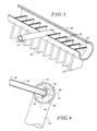
- FIG. 2-5 An exemplary embodiment of the invention is illustrated in Figs. 2-5, inclusive and will be described herein in the context of a so called "V" evaporator of the parallel flow type.
- the invention is not limited to such evaporators. It may be used with efficacy in any evaporator having a header that is in fluid communication with a plurality of spaced refrigerant passages.
- the evaporator includes an inlet header 20 in the form of an elongated tube. Also included is an outlet header 22. A series of flattened, multi-port tubes 24 interconnect headers 20 and 22. Serpentine fins 26 are disposed between adjacent ones of the flattened tubes 24.
- the outlet header 22 includes a single outlet fixture 28 which may be of conventional construction.
- the injectors 30, 32, 34 and 36 may be common tubes that all are connected to a conventional distributor 38 which in turn may be connected to a common source of liquid refrigerant, i.e., ultimately the condenser of a refrigeration system, whether used for pure refrigeration purposes, heat pumps or air-conditioning purposes or all three.
- each of the tubes 24 have an end 40 that extends a substantial distance into the interior of the inlet header 20.
- the tube ends 40 reveal that each tube itself includes a plurality of separate passages 42 which preferably are of a hydraulic diameter of 0.07" or less. Hydraulic diameter is as conventionally defined, namely, four times the cross sectional area of each passage 42 divided by the wetted perimeter of the passage.
- the ends 40 are spaced and as can be seen in Fig. 3, a representative of one of the injectors, namely the injector 34, is located between the ends of a pair of adjacent tubes 24.
- the injector 34 and the injectors 30, 32 and 36 are formed of a round tube of smaller diameter than the tube forming the inlet header 20.
- the injector 34 enters the header 20 at nominally right angles thereto as well as to the plane defined by the tubes 24 near the header 20.
- the injector 34 includes a sealed end 48 within the header 20. Oppositely thereof is a port 49 to be connected to receive refrigerant.
- the injector 34 also includes a first or primary discharge orifice 50 which discharges against the interior side 52 of the header 20 that is opposite from the side 44 whereat the tubes 24 enter the header 20.
- a secondary discharge orifice 54 is also located in the injector 34 within the header 20 on a common center line with the primary discharge orifice 50.
- the secondary discharge orifice 54 is of smaller size than the primary discharge orifice and directs liquid refrigerant toward the side 44.
- the point of injection may be at a location between adjacent ones of the tube ends 40 or at location aligned with a tube end.
- the spray of liquid emerging from the primary discharge orifice spreads along the interior side 52 of the header 20 to distribute the refrigerant along a substantial distance within the header so that the entirety of the tubes 24 between the locations of the injectors 30, 32, 34 and 36 receive refrigerant.
- only the primary discharge orifices 50 are required.
- those tubes in immediate proximity to the injectors 30, 32, 34 or 36 may not receive sufficient refrigerant because it is literally blown past their ends 40 as a result of the impingement on the inner surface 52.
- the secondary discharge orifices 54 may be provided in each injector 30, 32, 34 and 36 to assure that the tubes 24 closely adjacent each injector location receive an adequate supply of liquid refrigerant.
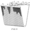
- Fig. 5 represents the infrared thermal image of an actual evaporator made according to the invention.
- the shaded areas thereon represent areas where superheated vapor flow is occurring It will be seen that the use of the invention in the evaporator Fig. 5 substantially reduces such areas to considerably improve the efficiency of operation of the evaporator over that depicted in Fig. 1.
- each injector is made of a tube having a 0.25" outside diameter and a 0.035" wall thickness.
- the primary discharge orifices 50 have a diameter of 0.125" while the secondary discharge orifices 54 have a diameter of 0.052".
- the evaporator has 45 of the flattened tubes 24 in its core, meaning 11.25 tubes 24 per injector.
- an evaporator made according to the invention achieves excellent distribution of incoming liquid refrigerant to improve the efficiency of operation.
- the structure employed is relatively simple in that the injectors may be made from tubing with the discharge orifices bored in them to the proper size. Consequently, a real improvement in efficiency can be obtained at minimal cost or complexity.
Landscapes
- Engineering & Computer Science (AREA)
- Physics & Mathematics (AREA)
- Mechanical Engineering (AREA)
- Thermal Sciences (AREA)
- General Engineering & Computer Science (AREA)
- Heat-Exchange Devices With Radiators And Conduit Assemblies (AREA)
- Filling Or Discharging Of Gas Storage Vessels (AREA)
- Vaporization, Distillation, Condensation, Sublimation, And Cold Traps (AREA)
- Gas Separation By Absorption (AREA)
Priority Applications (12)
| Application Number | Priority Date | Filing Date | Title |
|---|---|---|---|
| US08/954,646 US5910167A (en) | 1997-10-20 | 1997-10-20 | Inlet for an evaporator |
| EP99301250A EP1031802B1 (fr) | 1997-10-20 | 1999-02-22 | Admission améliorée d'un evaporateur |
| AT99301250T ATE301808T1 (de) | 1997-10-20 | 1999-02-22 | Verbesserter verdampfereintritt |
| ES99301250T ES2243031T3 (es) | 1997-10-20 | 1999-02-22 | Entrada mejorada para evaporador. |
| DE69926600T DE69926600T2 (de) | 1997-10-20 | 1999-02-22 | Verbesserter Verdampfereintritt |
| JP11044742A JP2000249428A (ja) | 1997-10-20 | 1999-02-23 | 蒸発器 |
| ZA9901447A ZA991447B (en) | 1997-10-20 | 1999-02-23 | Inlet for an evaporator. |
| TW088102618A TW406179B (en) | 1997-10-20 | 1999-02-23 | Improved inlet for an evaporator |
| AU18418/99A AU757774B2 (en) | 1997-10-20 | 1999-02-24 | Improved inlet for an evaporator |
| CA002262798A CA2262798A1 (fr) | 1997-10-20 | 1999-02-24 | Entree amelioree d'evaporateur |
| BR9909837-7A BR9909837A (pt) | 1997-10-20 | 1999-03-01 | Passagem melhorada para um evaporador |
| CN99103662A CN1133054C (zh) | 1997-10-20 | 1999-03-11 | 蒸发器 |
Applications Claiming Priority (8)
| Application Number | Priority Date | Filing Date | Title |
|---|---|---|---|
| US08/954,646 US5910167A (en) | 1997-10-20 | 1997-10-20 | Inlet for an evaporator |
| EP99301250A EP1031802B1 (fr) | 1997-10-20 | 1999-02-22 | Admission améliorée d'un evaporateur |
| JP11044742A JP2000249428A (ja) | 1997-10-20 | 1999-02-23 | 蒸発器 |
| ZA9901447A ZA991447B (en) | 1997-10-20 | 1999-02-23 | Inlet for an evaporator. |
| AU18418/99A AU757774B2 (en) | 1997-10-20 | 1999-02-24 | Improved inlet for an evaporator |
| CA002262798A CA2262798A1 (fr) | 1997-10-20 | 1999-02-24 | Entree amelioree d'evaporateur |
| BR9909837-7A BR9909837A (pt) | 1997-10-20 | 1999-03-01 | Passagem melhorada para um evaporador |
| CN99103662A CN1133054C (zh) | 1997-10-20 | 1999-03-11 | 蒸发器 |
Publications (2)
| Publication Number | Publication Date |
|---|---|
| EP1031802A1 true EP1031802A1 (fr) | 2000-08-30 |
| EP1031802B1 EP1031802B1 (fr) | 2005-08-10 |
Family
ID=32074891
Family Applications (1)
| Application Number | Title | Priority Date | Filing Date |
|---|---|---|---|
| EP99301250A Expired - Lifetime EP1031802B1 (fr) | 1997-10-20 | 1999-02-22 | Admission améliorée d'un evaporateur |
Country Status (12)
| Country | Link |
|---|---|
| US (1) | US5910167A (fr) |
| EP (1) | EP1031802B1 (fr) |
| JP (1) | JP2000249428A (fr) |
| CN (1) | CN1133054C (fr) |
| AT (1) | ATE301808T1 (fr) |
| AU (1) | AU757774B2 (fr) |
| BR (1) | BR9909837A (fr) |
| CA (1) | CA2262798A1 (fr) |
| DE (1) | DE69926600T2 (fr) |
| ES (1) | ES2243031T3 (fr) |
| TW (1) | TW406179B (fr) |
| ZA (1) | ZA991447B (fr) |
Cited By (1)
| Publication number | Priority date | Publication date | Assignee | Title |
|---|---|---|---|---|
| ITBO20120130A1 (it) * | 2012-03-14 | 2013-09-15 | Valmex S P A | Scambiatore di calore particolarmente adatto all'uso come evaporatore |
Families Citing this family (54)
| Publication number | Priority date | Publication date | Assignee | Title |
|---|---|---|---|---|
| US5910167A (en) * | 1997-10-20 | 1999-06-08 | Modine Manufacturing Co. | Inlet for an evaporator |
| US20030102113A1 (en) * | 2001-11-30 | 2003-06-05 | Stephen Memory | Heat exchanger for providing supercritical cooling of a working fluid in a transcritical cooling cycle |
| JPWO2004025207A1 (ja) * | 2002-09-10 | 2006-01-12 | ジーエーシー株式会社 | 熱交換器およびその製造方法 |
| US6804976B1 (en) * | 2003-12-12 | 2004-10-19 | John F. Dain | High reliability multi-tube thermal exchange structure |
| EP1548380A3 (fr) * | 2003-12-22 | 2006-10-04 | Hussmann Corporation | Evaporateur à tubes plats avec micro-distributeur |
| US7428919B2 (en) * | 2004-08-02 | 2008-09-30 | Young David P | Method and system for evaluating fluid flow through a heat exchanger |
| US7086249B2 (en) * | 2004-10-01 | 2006-08-08 | Advanced Heat Transfer, Llc | Refrigerant distribution device and method |
| US7331195B2 (en) * | 2004-10-01 | 2008-02-19 | Advanced Heat Transfer Llc | Refrigerant distribution device and method |
| BRPI0519937A2 (pt) * | 2005-02-02 | 2009-09-08 | Carrier Corp | trocador de calor, e, sistema de compressão de vapor refrigerante |
| JP2007113795A (ja) * | 2005-10-18 | 2007-05-10 | Usui Kokusai Sangyo Kaisha Ltd | 排気ガス冷却装置用多管式熱交換器 |
| US8561675B2 (en) * | 2005-12-29 | 2013-10-22 | Industrial Technology Research Institute | Spray type heat-exchanging unit |
| TWI291541B (en) * | 2005-12-29 | 2007-12-21 | Ind Tech Res Inst | A sprinkling type heat exchanger |
| WO2007094422A1 (fr) | 2006-02-15 | 2007-08-23 | Gac Corporation | Echangeur de chaleur |
| JP4812087B2 (ja) * | 2006-02-21 | 2011-11-09 | 新晃工業株式会社 | 空調機の一重管蒸気コイルの凍結防止及び熱応力破損防止構造 |
| WO2008045111A1 (fr) * | 2006-10-13 | 2008-04-17 | Carrier Corporation | Échangeur de chaleur multicanaux avec dispositif de détente multi-étage |
| WO2008064251A2 (fr) * | 2006-11-22 | 2008-05-29 | Johnson Controls Technology Company | Échangeur thermique multicanaux compact |
| WO2008064219A1 (fr) * | 2006-11-22 | 2008-05-29 | Johnson Controls Technology Company | Évaporateur multicanaux avec collecteur de mélange de flux |
| WO2008064247A1 (fr) * | 2006-11-22 | 2008-05-29 | Johnson Controls Technology Company | Échangeur de chaleur multicanal polyvalent |
| BRPI0811928A2 (pt) * | 2007-05-22 | 2014-11-25 | Behr Gmbh & Co Kg | Trocador de calor |
| US8166776B2 (en) | 2007-07-27 | 2012-05-01 | Johnson Controls Technology Company | Multichannel heat exchanger |
| US20090025405A1 (en) * | 2007-07-27 | 2009-01-29 | Johnson Controls Technology Company | Economized Vapor Compression Circuit |
| US7621148B1 (en) | 2007-08-07 | 2009-11-24 | Dain John F | Ultra-low temperature bio-sample storage system |
| JP5097472B2 (ja) * | 2007-08-10 | 2012-12-12 | Gac株式会社 | 熱交換器 |
| EP2193315B1 (fr) * | 2007-08-24 | 2011-10-12 | Johnson Controls Technology Company | Système de compression de vapeur et methode de controle d'un tel système |
| US7823394B2 (en) * | 2007-11-02 | 2010-11-02 | Reflect Scientific, Inc. | Thermal insulation technique for ultra low temperature cryogenic processor |
| CN101691981B (zh) * | 2009-07-23 | 2011-12-07 | 三花丹佛斯(杭州)微通道换热器有限公司 | 具有改进的制冷剂流体分配均匀性的多通道换热器 |
| US8439104B2 (en) * | 2009-10-16 | 2013-05-14 | Johnson Controls Technology Company | Multichannel heat exchanger with improved flow distribution |
| US20110139422A1 (en) * | 2009-12-15 | 2011-06-16 | Delphi Technologies, Inc. | Fluid distribution device |
| CN101865574B (zh) * | 2010-06-21 | 2013-01-30 | 三花控股集团有限公司 | 换热器 |
| CN102062499A (zh) * | 2010-12-22 | 2011-05-18 | 广东美的电器股份有限公司 | 平行流换热器装置及其控制方法 |
| US9651317B2 (en) * | 2011-01-21 | 2017-05-16 | Daikin Industries, Ltd. | Heat exchanger and air conditioner |
| BR112013032863B1 (pt) * | 2011-07-01 | 2020-12-15 | Equinor Energy As | Sistema de distribuição de fase múltipla, trocador de calor submarino e um método de controle de temperatura para hidrocarbonetos |
| CN102269486A (zh) * | 2011-07-12 | 2011-12-07 | 广东美的电器股份有限公司 | 平行流换热器和房间空调器 |
| ITBO20120131A1 (it) * | 2012-03-14 | 2013-09-15 | Valmex S P A | Scambiatore di calore particolarmente adatto all'uso come evaporatore |
| CN104272040B (zh) | 2012-04-26 | 2016-06-15 | 三菱电机株式会社 | 制冷剂分配器、具备此制冷剂分配器的热交换器、冷冻循环装置和空调机 |
| SI2674714T1 (sl) * | 2012-06-14 | 2019-11-29 | Alfa Laval Corp Ab | Ploščni toplotni izmenjevalnik z injekcijskimi sredstvi |
| SI2674716T1 (sl) * | 2012-06-14 | 2015-08-31 | Alfa Laval Corporate Ab | Ploščni toplotni izmenjevalec |
| CN102818401A (zh) * | 2012-08-06 | 2012-12-12 | 海信科龙电器股份有限公司 | 全铝空调器换热器 |
| GB2527682B (en) * | 2013-01-25 | 2019-05-08 | Trane Int Inc | Capacity modulating an expansion device of a HVAC system |
| CN104006576A (zh) * | 2013-02-25 | 2014-08-27 | 浙江盾安热工科技有限公司 | 一种换热器 |
| CN103486896B (zh) * | 2013-07-30 | 2015-05-27 | 杭州三花微通道换热器有限公司 | 集流管组件和具有该集流管组件的换热器 |
| EP3033579B1 (fr) | 2013-08-12 | 2017-08-02 | Carrier Corporation | Échangeur de chaleur et répartiteur de débit |
| ES2870720T3 (es) * | 2015-06-03 | 2021-10-27 | Alfa Laval Corp Ab | Un dispositivo colector para un sistema intercambiador de calor, un sistema intercambiador de calor y un método para calentar un fluido |
| USD787033S1 (en) * | 2015-12-24 | 2017-05-16 | Danfoss Micro Channel Heat Exchanger (Jiaxing) Co., Ltd. | Heat exchanger |
| CN105744805A (zh) * | 2016-04-15 | 2016-07-06 | 周哲明 | 一种多通道组合水冷板 |
| USD827795S1 (en) * | 2016-07-05 | 2018-09-04 | Danfoss Micro Channel Heat Exchanger (Jiaxing) Co., Ltd. | Heat exchanger |
| USD852338S1 (en) * | 2016-07-05 | 2019-06-25 | Danfoss Micro Channel Heat Exchanger (Jiaxing) Co., Ltd. | Heat exchanger |
| USD828910S1 (en) * | 2016-07-07 | 2018-09-18 | Danfoss Micro Channel Heat Exchanger (Jiaxing) Co., Ltd. | Heat exchanger |
| USD910821S1 (en) | 2016-08-26 | 2021-02-16 | Danfoss Micro Channel Heat Exchanger (Jiaxing) Co., Ltd. | Heat exchanger |
| US20190024954A1 (en) * | 2017-07-20 | 2019-01-24 | Modine Manufacturing Company | Heat Exchange System |
| JP7496832B2 (ja) * | 2019-10-10 | 2024-06-07 | 三菱電機株式会社 | 熱交換器、熱交換器ユニット、冷凍サイクル装置、及び熱交換部材の製造方法 |
| US11493277B2 (en) * | 2019-11-06 | 2022-11-08 | Carrier Corporation | Microchannel heat exchanger |
| CN112066602A (zh) * | 2020-09-14 | 2020-12-11 | 珠海格力电器股份有限公司 | 一种换热器及空调、空调控制方法及装置 |
| CN116222266A (zh) * | 2023-01-12 | 2023-06-06 | 浙江康盛热交换器有限公司 | 一种微通道换热器进口气流分配结构 |
Citations (7)
| Publication number | Priority date | Publication date | Assignee | Title |
|---|---|---|---|---|
| US3976128A (en) * | 1975-06-12 | 1976-08-24 | Ford Motor Company | Plate and fin heat exchanger |
| EP0501736A2 (fr) * | 1991-03-01 | 1992-09-02 | Modine Manufacturing Company | Evaporateur |
| US5341870A (en) | 1985-10-02 | 1994-08-30 | Modine Manufacturing Company | Evaporator or evaporator/condenser |
| US5533259A (en) | 1985-10-02 | 1996-07-09 | Modine Manufacturing Co. | Method of making an evaporator or evaporator/condenser |
| US5651268A (en) * | 1995-01-05 | 1997-07-29 | Nippondeso Co., Ltd. | Refrigerant evaporator |
| US5806586A (en) * | 1993-07-03 | 1998-09-15 | Ernst Flitsch Gmbh & Co. | Plate heat exchanger with a refrigerant distributor |
| US5910167A (en) * | 1997-10-20 | 1999-06-08 | Modine Manufacturing Co. | Inlet for an evaporator |
Family Cites Families (9)
| Publication number | Priority date | Publication date | Assignee | Title |
|---|---|---|---|---|
| US1684083A (en) * | 1927-06-02 | 1928-09-11 | Samuel C Bloom | Refrigerating coil |
| JPS5933819B2 (ja) * | 1979-03-27 | 1984-08-18 | 富士電機株式会社 | 冷却装置 |
| JPS5837090U (ja) * | 1981-08-29 | 1983-03-10 | 日本ラヂヱ−タ−株式会社 | ラジエ−タタンク |
| JPS63121292U (fr) * | 1987-01-30 | 1988-08-05 | ||
| JPH02219966A (ja) * | 1989-02-21 | 1990-09-03 | Matsushita Refrig Co Ltd | 冷媒分流器 |
| US5048602A (en) * | 1989-05-22 | 1991-09-17 | Showa Aluminum Kabushiki Kaisha | Heat exchangers |
| JPH0455693A (ja) * | 1990-06-21 | 1992-02-24 | Mitsubishi Electric Corp | 多管式熱交換器 |
| US5534202A (en) * | 1994-04-05 | 1996-07-09 | Roberts Filter Manufacturing Company | Air grid for underdrains and similar systems |
| JP3373940B2 (ja) * | 1994-07-14 | 2003-02-04 | シャープ株式会社 | 熱交換器 |
-
1997
- 1997-10-20 US US08/954,646 patent/US5910167A/en not_active Expired - Lifetime
-
1999
- 1999-02-22 AT AT99301250T patent/ATE301808T1/de not_active IP Right Cessation
- 1999-02-22 EP EP99301250A patent/EP1031802B1/fr not_active Expired - Lifetime
- 1999-02-22 ES ES99301250T patent/ES2243031T3/es not_active Expired - Lifetime
- 1999-02-22 DE DE69926600T patent/DE69926600T2/de not_active Expired - Fee Related
- 1999-02-23 TW TW088102618A patent/TW406179B/zh not_active IP Right Cessation
- 1999-02-23 ZA ZA9901447A patent/ZA991447B/xx unknown
- 1999-02-23 JP JP11044742A patent/JP2000249428A/ja active Pending
- 1999-02-24 AU AU18418/99A patent/AU757774B2/en not_active Ceased
- 1999-02-24 CA CA002262798A patent/CA2262798A1/fr not_active Abandoned
- 1999-03-01 BR BR9909837-7A patent/BR9909837A/pt not_active Application Discontinuation
- 1999-03-11 CN CN99103662A patent/CN1133054C/zh not_active Expired - Fee Related
Patent Citations (7)
| Publication number | Priority date | Publication date | Assignee | Title |
|---|---|---|---|---|
| US3976128A (en) * | 1975-06-12 | 1976-08-24 | Ford Motor Company | Plate and fin heat exchanger |
| US5341870A (en) | 1985-10-02 | 1994-08-30 | Modine Manufacturing Company | Evaporator or evaporator/condenser |
| US5533259A (en) | 1985-10-02 | 1996-07-09 | Modine Manufacturing Co. | Method of making an evaporator or evaporator/condenser |
| EP0501736A2 (fr) * | 1991-03-01 | 1992-09-02 | Modine Manufacturing Company | Evaporateur |
| US5806586A (en) * | 1993-07-03 | 1998-09-15 | Ernst Flitsch Gmbh & Co. | Plate heat exchanger with a refrigerant distributor |
| US5651268A (en) * | 1995-01-05 | 1997-07-29 | Nippondeso Co., Ltd. | Refrigerant evaporator |
| US5910167A (en) * | 1997-10-20 | 1999-06-08 | Modine Manufacturing Co. | Inlet for an evaporator |
Cited By (1)
| Publication number | Priority date | Publication date | Assignee | Title |
|---|---|---|---|---|
| ITBO20120130A1 (it) * | 2012-03-14 | 2013-09-15 | Valmex S P A | Scambiatore di calore particolarmente adatto all'uso come evaporatore |
Also Published As
| Publication number | Publication date |
|---|---|
| CA2262798A1 (fr) | 2000-08-24 |
| US5910167A (en) | 1999-06-08 |
| ZA991447B (en) | 1999-11-24 |
| DE69926600D1 (de) | 2005-09-15 |
| AU1841899A (en) | 2000-08-31 |
| CN1133054C (zh) | 2003-12-31 |
| EP1031802B1 (fr) | 2005-08-10 |
| ATE301808T1 (de) | 2005-08-15 |
| JP2000249428A (ja) | 2000-09-14 |
| DE69926600T2 (de) | 2006-04-06 |
| ES2243031T3 (es) | 2005-11-16 |
| TW406179B (en) | 2000-09-21 |
| CN1266977A (zh) | 2000-09-20 |
| AU757774B2 (en) | 2003-03-06 |
| BR9909837A (pt) | 2000-12-19 |
Similar Documents
| Publication | Publication Date | Title |
|---|---|---|
| US5910167A (en) | Inlet for an evaporator | |
| KR100830301B1 (ko) | 헤더 내의 다단 유체 팽창을 이용한 열교환기 | |
| EP0501736B1 (fr) | Evaporateur | |
| US8235101B2 (en) | Parallel flow heat exchanger for heat pump applications | |
| AU2005326711B2 (en) | Parallel flow heat exchangers incorporating porous inserts | |
| CN101120225B (zh) | 集管中具有流体膨胀的热交换器 | |
| US20080190134A1 (en) | Refrigerant flow distributor | |
| US20080105420A1 (en) | Parallel Flow Heat Exchanger With Crimped Channel Entrance | |
| US20200088451A1 (en) | Heat exchanger for heat pump applications | |
| US20220090864A1 (en) | Heat exchanger assembly | |
| JPH06300477A (ja) | 熱交換器 | |
| US12392505B2 (en) | Air conditioner | |
| JP2644900B2 (ja) | 熱交換器 | |
| MXPA99001867A (es) | Entrada mejorada para un evaporador | |
| RU2226659C2 (ru) | Усовершенствованный впуск для испарителя (варианты) | |
| KR100557317B1 (ko) | 개량된 증발기용 인렛 | |
| JP2574488B2 (ja) | 熱交換器 | |
| HK1106285B (en) | Heat exchanger with multiple stage fluid expansion in header | |
| HK1118331B (en) | Heat exchanger with fluid expansion in header |
Legal Events
| Date | Code | Title | Description |
|---|---|---|---|
| PUAI | Public reference made under article 153(3) epc to a published international application that has entered the european phase |
Free format text: ORIGINAL CODE: 0009012 |
|
| AK | Designated contracting states |
Kind code of ref document: A1 Designated state(s): AT DE ES FR GB IT NL SE |
|
| AX | Request for extension of the european patent |
Free format text: AL;LT;LV;MK;RO;SI |
|
| 17P | Request for examination filed |
Effective date: 20010217 |
|
| AKX | Designation fees paid |
Free format text: AT DE ES FR GB IT NL SE |
|
| 17Q | First examination report despatched |
Effective date: 20030131 |
|
| GRAP | Despatch of communication of intention to grant a patent |
Free format text: ORIGINAL CODE: EPIDOSNIGR1 |
|
| GRAS | Grant fee paid |
Free format text: ORIGINAL CODE: EPIDOSNIGR3 |
|
| GRAA | (expected) grant |
Free format text: ORIGINAL CODE: 0009210 |
|
| AK | Designated contracting states |
Kind code of ref document: B1 Designated state(s): AT DE ES FR GB IT NL SE |
|
| PG25 | Lapsed in a contracting state [announced via postgrant information from national office to epo] |
Ref country code: NL Free format text: LAPSE BECAUSE OF FAILURE TO SUBMIT A TRANSLATION OF THE DESCRIPTION OR TO PAY THE FEE WITHIN THE PRESCRIBED TIME-LIMIT Effective date: 20050810 Ref country code: AT Free format text: LAPSE BECAUSE OF FAILURE TO SUBMIT A TRANSLATION OF THE DESCRIPTION OR TO PAY THE FEE WITHIN THE PRESCRIBED TIME-LIMIT Effective date: 20050810 |
|
| REG | Reference to a national code |
Ref country code: GB Ref legal event code: FG4D |
|
| REF | Corresponds to: |
Ref document number: 69926600 Country of ref document: DE Date of ref document: 20050915 Kind code of ref document: P |
|
| PG25 | Lapsed in a contracting state [announced via postgrant information from national office to epo] |
Ref country code: SE Free format text: LAPSE BECAUSE OF FAILURE TO SUBMIT A TRANSLATION OF THE DESCRIPTION OR TO PAY THE FEE WITHIN THE PRESCRIBED TIME-LIMIT Effective date: 20051110 |
|
| REG | Reference to a national code |
Ref country code: ES Ref legal event code: FG2A Ref document number: 2243031 Country of ref document: ES Kind code of ref document: T3 |
|
| NLV1 | Nl: lapsed or annulled due to failure to fulfill the requirements of art. 29p and 29m of the patents act | ||
| PG25 | Lapsed in a contracting state [announced via postgrant information from national office to epo] |
Ref country code: GB Free format text: LAPSE BECAUSE OF NON-PAYMENT OF DUE FEES Effective date: 20060222 |
|
| PG25 | Lapsed in a contracting state [announced via postgrant information from national office to epo] |
Ref country code: ES Free format text: LAPSE BECAUSE OF NON-PAYMENT OF DUE FEES Effective date: 20060223 |
|
| PGFP | Annual fee paid to national office [announced via postgrant information from national office to epo] |
Ref country code: IT Payment date: 20060228 Year of fee payment: 8 |
|
| PGFP | Annual fee paid to national office [announced via postgrant information from national office to epo] |
Ref country code: DE Payment date: 20060331 Year of fee payment: 8 |
|
| ET | Fr: translation filed | ||
| PLBE | No opposition filed within time limit |
Free format text: ORIGINAL CODE: 0009261 |
|
| STAA | Information on the status of an ep patent application or granted ep patent |
Free format text: STATUS: NO OPPOSITION FILED WITHIN TIME LIMIT |
|
| 26N | No opposition filed |
Effective date: 20060511 |
|
| GBPC | Gb: european patent ceased through non-payment of renewal fee |
Effective date: 20060222 |
|
| REG | Reference to a national code |
Ref country code: ES Ref legal event code: FD2A Effective date: 20060223 |
|
| PG25 | Lapsed in a contracting state [announced via postgrant information from national office to epo] |
Ref country code: DE Free format text: LAPSE BECAUSE OF NON-PAYMENT OF DUE FEES Effective date: 20070901 |
|
| PGFP | Annual fee paid to national office [announced via postgrant information from national office to epo] |
Ref country code: FR Payment date: 20080218 Year of fee payment: 10 |
|
| PG25 | Lapsed in a contracting state [announced via postgrant information from national office to epo] |
Ref country code: IT Free format text: LAPSE BECAUSE OF NON-PAYMENT OF DUE FEES Effective date: 20070222 |
|
| REG | Reference to a national code |
Ref country code: FR Ref legal event code: ST Effective date: 20091030 |
|
| PG25 | Lapsed in a contracting state [announced via postgrant information from national office to epo] |
Ref country code: FR Free format text: LAPSE BECAUSE OF NON-PAYMENT OF DUE FEES Effective date: 20090302 |