EP1032060B1 - Batterie-Pack - Google Patents
Batterie-Pack Download PDFInfo
- Publication number
- EP1032060B1 EP1032060B1 EP00103535A EP00103535A EP1032060B1 EP 1032060 B1 EP1032060 B1 EP 1032060B1 EP 00103535 A EP00103535 A EP 00103535A EP 00103535 A EP00103535 A EP 00103535A EP 1032060 B1 EP1032060 B1 EP 1032060B1
- Authority
- EP
- European Patent Office
- Prior art keywords
- battery pack
- terminal
- recited
- sealing plate
- protective component
- Prior art date
- Legal status (The legal status is an assumption and is not a legal conclusion. Google has not performed a legal analysis and makes no representation as to the accuracy of the status listed.)
- Expired - Lifetime
Links
- 230000001681 protective effect Effects 0.000 claims description 81
- 238000007789 sealing Methods 0.000 claims description 51
- 230000002745 absorbent Effects 0.000 claims description 31
- 239000002250 absorbent Substances 0.000 claims description 31
- 239000000463 material Substances 0.000 claims description 31
- 239000003792 electrolyte Substances 0.000 claims description 24
- 238000004321 preservation Methods 0.000 claims description 23
- 239000010408 film Substances 0.000 claims description 4
- 238000005192 partition Methods 0.000 claims description 4
- 239000004033 plastic Substances 0.000 claims description 4
- 239000010409 thin film Substances 0.000 claims description 4
- 239000011810 insulating material Substances 0.000 claims description 3
- 230000000149 penetrating effect Effects 0.000 claims description 3
- 239000000835 fiber Substances 0.000 claims description 2
- 239000004745 nonwoven fabric Substances 0.000 claims description 2
- 239000002984 plastic foam Substances 0.000 claims description 2
- 239000002184 metal Substances 0.000 claims 1
- 239000007789 gas Substances 0.000 description 10
- 238000003466 welding Methods 0.000 description 8
- 230000006378 damage Effects 0.000 description 5
- 230000007257 malfunction Effects 0.000 description 3
- 229920006257 Heat-shrinkable film Polymers 0.000 description 2
- XEEYBQQBJWHFJM-UHFFFAOYSA-N Iron Chemical compound [Fe] XEEYBQQBJWHFJM-UHFFFAOYSA-N 0.000 description 2
- PXHVJJICTQNCMI-UHFFFAOYSA-N Nickel Chemical compound [Ni] PXHVJJICTQNCMI-UHFFFAOYSA-N 0.000 description 2
- 230000002159 abnormal effect Effects 0.000 description 2
- 239000000853 adhesive Substances 0.000 description 2
- 230000001070 adhesive effect Effects 0.000 description 2
- 238000003780 insertion Methods 0.000 description 2
- 230000037431 insertion Effects 0.000 description 2
- WABPQHHGFIMREM-UHFFFAOYSA-N lead(0) Chemical compound [Pb] WABPQHHGFIMREM-UHFFFAOYSA-N 0.000 description 2
- 230000002093 peripheral effect Effects 0.000 description 2
- 229910000838 Al alloy Inorganic materials 0.000 description 1
- 235000009854 Cucurbita moschata Nutrition 0.000 description 1
- 240000001980 Cucurbita pepo Species 0.000 description 1
- 235000009852 Cucurbita pepo Nutrition 0.000 description 1
- UFHFLCQGNIYNRP-UHFFFAOYSA-N Hydrogen Chemical compound [H][H] UFHFLCQGNIYNRP-UHFFFAOYSA-N 0.000 description 1
- HBBGRARXTFLTSG-UHFFFAOYSA-N Lithium ion Chemical compound [Li+] HBBGRARXTFLTSG-UHFFFAOYSA-N 0.000 description 1
- 238000010521 absorption reaction Methods 0.000 description 1
- 239000002313 adhesive film Substances 0.000 description 1
- XAGFODPZIPBFFR-UHFFFAOYSA-N aluminium Chemical compound [Al] XAGFODPZIPBFFR-UHFFFAOYSA-N 0.000 description 1
- 229910052782 aluminium Inorganic materials 0.000 description 1
- OJIJEKBXJYRIBZ-UHFFFAOYSA-N cadmium nickel Chemical compound [Ni].[Cd] OJIJEKBXJYRIBZ-UHFFFAOYSA-N 0.000 description 1
- 238000003776 cleavage reaction Methods 0.000 description 1
- 230000007797 corrosion Effects 0.000 description 1
- 238000005260 corrosion Methods 0.000 description 1
- 230000001419 dependent effect Effects 0.000 description 1
- 239000008151 electrolyte solution Substances 0.000 description 1
- 238000004880 explosion Methods 0.000 description 1
- 239000001257 hydrogen Substances 0.000 description 1
- 229910052739 hydrogen Inorganic materials 0.000 description 1
- 229910052742 iron Inorganic materials 0.000 description 1
- 229910001416 lithium ion Inorganic materials 0.000 description 1
- 230000005012 migration Effects 0.000 description 1
- 238000013508 migration Methods 0.000 description 1
- 229910052759 nickel Inorganic materials 0.000 description 1
- 238000012856 packing Methods 0.000 description 1
- 230000035515 penetration Effects 0.000 description 1
- 230000007017 scission Effects 0.000 description 1
- 235000020354 squash Nutrition 0.000 description 1
Images


Classifications
-
- H—ELECTRICITY
- H01—ELECTRIC ELEMENTS
- H01M—PROCESSES OR MEANS, e.g. BATTERIES, FOR THE DIRECT CONVERSION OF CHEMICAL ENERGY INTO ELECTRICAL ENERGY
- H01M50/00—Constructional details or processes of manufacture of the non-active parts of electrochemical cells other than fuel cells, e.g. hybrid cells
- H01M50/50—Current conducting connections for cells or batteries
- H01M50/572—Means for preventing undesired use or discharge
- H01M50/574—Devices or arrangements for the interruption of current
- H01M50/581—Devices or arrangements for the interruption of current in response to temperature
-
- H—ELECTRICITY
- H01—ELECTRIC ELEMENTS
- H01M—PROCESSES OR MEANS, e.g. BATTERIES, FOR THE DIRECT CONVERSION OF CHEMICAL ENERGY INTO ELECTRICAL ENERGY
- H01M2200/00—Safety devices for primary or secondary batteries
- H01M2200/10—Temperature sensitive devices
- H01M2200/106—PTC
-
- H—ELECTRICITY
- H01—ELECTRIC ELEMENTS
- H01M—PROCESSES OR MEANS, e.g. BATTERIES, FOR THE DIRECT CONVERSION OF CHEMICAL ENERGY INTO ELECTRICAL ENERGY
- H01M50/00—Constructional details or processes of manufacture of the non-active parts of electrochemical cells other than fuel cells, e.g. hybrid cells
- H01M50/50—Current conducting connections for cells or batteries
- H01M50/572—Means for preventing undesired use or discharge
- H01M50/574—Devices or arrangements for the interruption of current
- H01M50/583—Devices or arrangements for the interruption of current in response to current, e.g. fuses
-
- Y—GENERAL TAGGING OF NEW TECHNOLOGICAL DEVELOPMENTS; GENERAL TAGGING OF CROSS-SECTIONAL TECHNOLOGIES SPANNING OVER SEVERAL SECTIONS OF THE IPC; TECHNICAL SUBJECTS COVERED BY FORMER USPC CROSS-REFERENCE ART COLLECTIONS [XRACs] AND DIGESTS
- Y02—TECHNOLOGIES OR APPLICATIONS FOR MITIGATION OR ADAPTATION AGAINST CLIMATE CHANGE
- Y02E—REDUCTION OF GREENHOUSE GAS [GHG] EMISSIONS, RELATED TO ENERGY GENERATION, TRANSMISSION OR DISTRIBUTION
- Y02E60/00—Enabling technologies; Technologies with a potential or indirect contribution to GHG emissions mitigation
- Y02E60/10—Energy storage using batteries
Definitions
- the present invention relates to a battery pack according to the preamble of claim 1.
- the preamble of claim 1 is based on prior art according to US-A-5 705 290 or FR-A-2 743 452. Both documents employ a pressure sensitive safety device which is responsive to increased internal pressure of a secondary battery cell by breaking a circuit to cut off the current. Such safety device and current cutoff mechanism is responsive only to an abnormally high internal pressure, not temperature nor electric current flow.
- a known battery pack with built-in plural cylindrical batteries 124 includes a built-in protective componen 103 to avoid its use under abnormal conditions of temperature or electric current.
- the protective component 103 cuts the electric current off if the temperature of the battery raises abnormally high or the current is abnormally high.
- a thermal fuse or a PTC is used as this type of protective component.
- a thermal fuse does blowout so the current is cut if the battery temperature goes higher than a predetermined temperature.
- a PTC raises its electrical resistance rapidly so the current hardly flows if the temperature raises due to a high current.
- the battery pack includes the protective component 103 at the space between batteries 124 in a case 125.
- the protective component 103 can be built-in using the cleavage space between the cylindrical batteries efficiently.
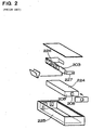
- a space is provided between a battery 224 and a case 225 such that a printed circuit board 226 is placed therein, a protective component 203 for the batteries 224 being provided on the printed circuit board 226.
- the battery pack with the structure as shown in Fig. 2 requires larger size of the case 225, since it needs an extra space for providing the built-in protective component 203. In addition, it is difficult to fix the printed circuit board 226 and the protective component 203 at predetermined position between the case 225 and the battery 224 without displacing them. In case that the printed circuit board 226 or the protective component 203 move inside of the case 225, it would deteriorate the reliability, because its vibrations might cause malfunction. Furthermore, as shown in Fig. 2, the battery pack providing the protective component 203 between the side of the battery 224 and the case 225 make the protective component 203 apart from a terminal 208 of a sealing plate 205. Consequently the connection of the protective component 203 to the terminal 208 of the sealing plate 205 is troublesome and it also needs a lead plate 227 elongated.
- the present invention has been developed to solve these drawbacks.
- the object of the present invention is to provide a battery pack with a built-in protective component, which has wholly compact size and includes a protective component built-in.
- the battery pack with built-in protective component of the present invention comprises a cell, a terminal holder and battery protective component.
- the cell seals tightly an opening of a sheathing case with a sealing plate which has a terminal protruding from its surface.
- the terminal holder is placed at which it covers the sealing plate of the cell, providing storage space to include the protective component between the sealing plate and the terminal holder.
- the terminal holder is made of an insulating material.
- the protective component is set in the storage space provided between the terminal holder and the sealing plate except terminal portion, in which the lower part of the protective component is positioned lower than the upper end of the terminal.
- the battery pack with the built-in protective component of this structure has the advantages to achieve overall compact size battery pack even having a built-in protective component, and to mount the protective component at a predetermined position so that it does not move around thereafter. These features are achieved by the battery pack providing a storage space between the sealing plate and the terminal holder, and the protective component positioned, other than terminal portion, making its lower portion lower than the upper end of the terminal.
- the cell with its terminal protruding from the sealing plate is provided with the terminal holder while it covers the sealing plate so that storage space is defined provided, except where the terminal is located, by virtue of protruding terminal.
- the battery pack of the present invention uses this storage space to store its protective component.
- the battery pack of this structure utilizes the overall compact size while including its protective component inside within fairly reduced space, utilizing unique structure of the cell and the terminal holder so that the space can be effectively used.
- the above battery pack has another advantageous feature to locate and maintain the protective component at a predetermined position in ideal conditions regardless of the outer shape of batteries, provided a storage space for the protective component by particularly configuring the terminal holder and peripheral structure of the sealing plate of the cell.
- the battery pack of the present invention is still advantageous for easy connection with the protective component using short lead wire, because the protective component can be placed nearby the terminal of the sealing plate.
- the battery pack employs, for example, a thermal fuse or a PTC, as the protective component, and disposes the protective component, preferably in a storage space at the lower portion of the terminal holder, having protective component close to the sealing plate of the cell.
- a thermal fuse or a PTC as the protective component
- the present invention provides a battery pack with a built-in protective component, in which it can fix the protective component at predetermined position without moving thereafter.
- the present invention provides a battery pack with a built-in protective component, in which it can connect the protective component to its terminals of a sealing plate thereof via short lead wire.
- rechargeable batteries like lithium ion rechargeable batteries, nickel hydrogen batteries, or nickel cadmium batteries are provided with a safety valve to prevent the explosion of an outer sheathing case in case used under abnormal conditions.
- the safety valve opens to exhaust the gas inside of the battery if the internal pressure of the battery is abnormally high. Sometimes the internal pressure of a battery reaches abnormally high when gas is produced inside of the battery by over-current flow or overcharged. If the internal pressure of the battery is high, it is necessary to exhaust the gas by opening the safety valve since it would lead to a dangerous condition to cause the destruction of the sheathing case.
- the safety valve When the safety valve opens, the gas filling inside of the battery will be exhausted. At that time, it may also exhaust electrolytic solution together with the gas.
- the electrolyte exhausted from the battery may influence a charger on which the battery is mounted and damage them or an electronic device thereof.
- the electrolyte attaches contact points of terminals, it corrodes them and causes insufficient contact. Also, if the electrolyte adheres to the printed circuit board, it causes some drawbacks like corrosion of the conductive portion or short circuits at the conductive portion due to migration.
- some chargers have been developed such as a charger provided with a drainage to easily exhaust the leaked electrolyte.
- the drainage of the charger can prevent large amount of leaked electrolyte ponded inside of the case.
- the electrolyte leaked from the battery adheres to the terminal contact of the charger and inner surface of the case, thus it causes a malfunction.
- a further embodiment of the present invention solves these drawbacks.
- Such further embodiment of the present invention provides batteries which absorb an electrolyte leaked from batteries so that it effectively prevents the damage of the electronic device due to the electrolyte.
- the battery pack of the present invention provides a preservation space between the terminal holder and the sealing plate such that an absorbent material is placed there to further prevent the damages caused by electrolyte.
- the battery pack with this structure has the advantageous feature to absorb the electrolyte leaked from the battery and thus to effectively prevent the damages to the electronic device due to the electrolyte.
- the battery pack of this structure also has the advantageous feature to efficiently prevent the drawback for the electronic device due to the electrolyte by the effective absorption of the electrolyte of the battery, because an absorbent material is placed in the preservation space provided between the sealing plate of the cell and the terminal holder.
- the battery pack can use this space so efficiently that the absorbent material is provided, and easily and precisely locate the absorbent material at prescribed location.
- a battery pack shown in an exploded oblique view of Fig. 3 comprises a cell 1, a terminal holder 2, a moisture absorbent material 20 and a protective component 3.
- the opening of a sheathing case 4 is sealed air tightly by the sealing plate 5.
- a flange 6 is provided at the circumference of the sealing plate 5 of the cell 1, being protruded to define a hollow section 7 within the flange 6.
- the flange 6 is configured by protruding the rim of the opening of the sheathing case 4 from the sealing plate 5 as the opening edge of the sheathing case 4.
- This cell was manufactured by introducing the sealing plate 5 into the opening of the sheathing case 4, then laser-welding the sealing plate 5 and the sheathing case 4 such that the sheathing case 4 was air tightly sealed.
- the sheathing case 4 is manufactured by presswork of metallic sheet like aluminum, aluminum alloy or metalclad iron sheet to form a fistulous container with bottom side sealed.
- the sheathing case 4 in Fig. 3 has a shape of which a cylindrical or cylindroid cylinder is pressed with particular thickness.
- the sheathing cases may be a rectangular, cylindrical or cylindroid cylinder (not illustrated).
- the sealing plate 5 is fixed at which terminal 8 is a center.
- the terminal 8 is fixed air-tightly insulated from metallic sealing plate 5 via insulating packing 9.
- the terminal 8 protrudes from the surface of the sealing plate 5.
- a safety valve can be provided inside of the terminal.
- the terminal with a built-in safety valve is provided with a perforation hole to exhaust gas trapped inside the sheathing case.
- the battery pack provided with a safety valve at the terminal absorbs and eliminates an electrolyte leaked through the perforation hole by the absorbent material.
- the sealing plate 5 shown in Fig. 3 has a leaking hole 10 at a location other than the terminal 8, and a safety valve 11 is provided on the leaking hole 10.
- the safety valve 11 is composed of a thin film which is broken by the internal pressure of the battery, the thin film being air tightly fixed at the inner face of the leaking hole 10.
- the thin film of the safety valve 11 seals the leaking hole 10 air tightly when the internal pressure of the battery is lower than the predetermined pressure. If the internal pressure of the battery is higher than the predetermined pressure, the film is broken so that the gas trapped inside the battery is exhausted outside.
- the terminal holder 2 has an attachment flange 12 protruding downwardly, the attachment flange 12 being inserted into the hollow section 7 of the cell 1. Furthermore, the terminal holder 2 has a storage space 13 to hold the protective component 3 for the battery and a preservation space 19 to hold the absorbent material 20 at the lower face.
- This terminal holder 2 is made of an insulating material like plastic and the like, a terminal plate 14 being fixed at its upper face. It is easy to mass-produce the plastic terminal holder 2 efficiently by insertion forming of the metallic terminal plate 14. As shown in Fig. 3 and Fig. 4, the terminal plate 14 has a shape which covers upper side of the terminal holder 2 substantially other than its circumference.
- the terminal holder 2 shown in Fig. 3 provides a rib at its circumference protruding downwardly so as to form the attachment flange 12.
- the rib forms a ditch on the outer circumference so that the flange 6 provided on the rim of the cell 1 is inserted into the ditch.
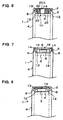
- Fig. 5 and Fig. 6 show the insertion of the flange 6 of the cell 1 into the rib of the terminal holder 2.
- the terminal holder 2 has the storage space 13 to hold the protective component 3 and the preservation space 19 to hold the absorbent material 20 provided inside of the rib.
- the protective component 3 mounted in the storage space 13 has one lead 15 contacted on the top side of the terminal 8 of the sealing plate 5, and another lead 15 connected to the terminal plate 14.
- the body of the protective component 3 is connected to the lower side of the lead and this body is provided in the storage space 13.
- the protective component 3 is held between the sealing plate 5 and the terminal holder 2, and located the storage space 13 other than the terminal 8 being, in Fig. 3, the protective-component 3 being held right of the terminal 8.
- the lower side of the protective component 3 is positioned lower than the top side level of the terminal 8.
- a penetration hole 16 is provided at the edge of the terminal holder 2, according to Fig. 5, the right hand edge of the terminal holder 2.
- the terminal holder 2 shown in Fig. 5 forms a protrusion 17 integrally, which protrudes downwardly so as to insert into a small hole 15A opened at the lead 15 of the protective component 3 to hold the protective component 3 at the right position.
- the terminal holder 2 with this structure has the feature to allow the setting of the protective component 3 at a precise position in the storage space 13. This is because the protrusion 17 of the terminal holder 2 is inserted into the small hole 15A opened at the lead 15 of the protective component 3 allowing the protective component 3 to be set at a decided position.
- the protective component 3 may be connected with the terminal holder 2 by heat welding the protrusion 17 inserted into the small hole 15A.
- the terminal holder 2 shown in this Fig. defines a connecting hole 18 at the center penetrating therethrough to connect the lead 15 of the protective component 3 to the terminal 8 of the sealing plate 5.
- the connecting hole 18 also goes through the terminal plate 14 attached to the terminal holder 2.
- the lead 15 of the protective component 3 is deposited on the terminal 8 by introducing an electrode for spot welding rod through the connecting hole 18 and spot-welding them.
- the terminal holder 2 shown in this Fig. has the storage space 13 at the right side and the preservation space 19 at the left side to hold the absorbent material 20.
- the preservation space 19 is surrounded by the rib and with upper side enclosed by the terminal plate 14 inserted into and fixed on the terminal holder 2.
- a partition 21 is provided, being connected to the surrounding rib.
- the partition 21 divides the preservation space 19 and the storage space 13, and prevents the electrolyte, which has leaked and absorbed by the absorbent material 20, from leaking outside.
- the partition 21 shown in this Fig. has a 2 row structure to secure to prevent the leaked electrolyte from the absorbent material 20 from leaking from the preservation space 19.
- the rib provided at the terminal holder 2 peripherally to form the preservation space 19 defines a notch section 22 to exhaust the gas passed through the safety valve 11 outside.
- the absorbent material 20 absorbs and maintains the electrolyte leaked from the battery.
- the absorbent material is made by such as a non-woven fabric aggregated by fine fibers solidly, filter paper or a minute open-cell plastic foam.
- the absorbent material 20 has a size enough to insert into the preservation space 19, in other words, shape and size are substantially same as or slightly smaller than the inner size of the preservation space 19. Also the absorbent material 20 opens an intake hole 20A at which it faces and corresponds to the leaking hole 10 of the safety valve 11.
- the thickness of the absorbent material 20 is substantially same as the height of the preservation space 19 or slightly thicker than the height of the preservation space 19 when not being pressed, so that it can be stored slightly compressed into the preservation space 19.
- This absorbent material 20 fays its bottom with the sealing plate 5 so that it absorbs the electrolyte drained from the safety valve 11 effectively.
- the absorbent material 20 with the intake hole 20A facing the leaking hole 10 of the sealing plate 5 does not seal the opening of the leaking hole 10.
- the safety valve 11 allows smooth exhaustion of the leaking electrolyte and gas through the leaking hole 10.
- the gas exhausted through the leaking hole 10 is led to the intake hole 20A then, ejected through the absorbent material 20.
- the electrolyte is absorbed by the absorbent material 20 from the intake hole 20A.
- the intake hole of the absorbent material may be opened at the lower side, while sealing the upper side without penetrating therethrogh.
- the protective component 3 comprises a thermal fuse which will blow out at predetermined temperature.
- the thermal fuse blows out to cut the current of the cell 1 off when the temperature of the cell 1 is higher than the set temperature.
- the battery pack of the present invention does not limit a protective component 3 to a thermal fuse.
- a PTC may be used as protective component 3.
- a PTC increases electrical resistance dramatically at predetermined temperature such that the current flowing through the cell 1 is extremely reduced, substantially it cuts the current off.
- the protective component 3 connects the lead 15 at both ends.
- the lead 15 is made by a thin metallic plate, which is connected to the terminal 8 and the terminal plate 14 by spot welding. As shown in Fig. 4, the lead 15 inserted into the through hole 16 of the terminal holder 2 is bent along the terminal holder 2 and connected to the upper side of the terminal plate 14 by welding.
- the battery pack with the above mentioned structure is manufactured by following steps.
Landscapes
- Chemical & Material Sciences (AREA)
- Chemical Kinetics & Catalysis (AREA)
- Electrochemistry (AREA)
- General Chemical & Material Sciences (AREA)
- Battery Mounting, Suspending (AREA)
- Connection Of Batteries Or Terminals (AREA)
Claims (21)
- Batteriesatz mit:einem Mantelgehäuse (4);einer Zelle (1), an der eine Öffnung des Mantelgehäuses (4) mit einer Dichtplatte (5) luftdicht verschlossen ist, wobei die Dichtplatte eine Klemme (8) hat, die von ihrer Oberfläche vorsteht; undeinem Sicherheitsventil (11), das auf der Dichtplatte (5) gebildet ist, um ein Gas aus dem Inneren der Zelle (1) abzulassen, wenn der innere Druck der Zelle (1) hoch ist,gekennzeichnet durch ein Schutzbauteil (3) zum Erfassen einer Temperatur der Zelle (1) oder von elektrischem Strom und zum Unterbrechen des Stromflusses aus der Zelle (1), wenn die Temperatur der Batterie abnormal hoch ansteigt oder wenn der Strom abnormal stark ist;durch einen Klemmenhalter (2), der in der Position angeordnet ist, in der er die Dichtplatte (5) der Zelle (1) bedeckt, und der einen Aufnahmeraum (13) zum Aufnehmen des Schutzbauteils (3) innen zwischen der Dichtplatte (5) und dem Klemmenhalter (2) hat und selbst aus einem Isoliermaterial hergestellt ist; wobei das Schutzbauteil (3) in dem Aufnahmeraum (13) angeordnet ist, der zwischen dem Klemmenhalter (2) und der Dichtplatte (5) gebildet ist, und in einem anderen Bereich als die Klemme (8), wobei die untere Seite des Schutzbauteils (3) niedriger ist als die Höhe der Oberseite der Klemme (8), und wobei das Schutzbauteil (3) relativ zu der Klemme (8) auf der zu dem Sicherheitsventil (11) entgegengesetzten Seite angeordnet ist.
- Batteriesatz nach Anspruch 1, wobei die Zelle (1) einen Flansch (6) hat, der an dem Rand der Dichtplatte (5) vorsteht, der Klemmenhalter (2) einen Befestigungsflansch (12) zum Einführen in die innere Seite des Flansches hat und der Befestigungsflansch (12) in einen hohlen Abschnitt der Zelle (1) eingeführt ist, um so den Aufnahmeraum (13) zwischen dem Klemmenhalter (2) und der Dichtplatte (5) zu bilden.
- Batteriesatz nach Anspruch 1 oder 2, wobei das Schutzbauteil (3) Anschlüsse (15) hat, wobei die Anschlüsse mit der oberen Seite der Klemme (8) verbunden sind und wobei der Körper des Schutzbauteils (3) mit der unteren Seite der Anschlüsse (15) verbunden und in dem Aufnahmeraum (13) befestigt ist.
- Batteriesatz nach einem der vorhergehenden Ansprüche, wobei das Schutzbauteil (3) in dem Aufnahmeraum (13) befestigt ist, der sich zwischen der Dichtplatte (5) und dem Klemmenhalter (2) befindet.
- Batteriesatz nach Anspruch 4, wobei das Schutzbauteil (3) auf der Oberfläche der Dichtplatte (5) angebracht ist.
- Batteriesatz nach Anspruch 3, wobei einer der Anschlüsse (15) des Schutzbauteils (3) mit der Klemme (8) verbunden ist, die auf der Dichtplatte (5) vorgesehen ist, und wobei der andere Anschluss den Klemmenhalter (2) durchdringt und mit der Anschlussplatte (14) verbunden ist, die auf der oberen Seite des Klemmenhalters (2) befestigt ist.
- Batteriesatz nach einem der vorhergehenden Ansprüche, wobei das Schutzbauteil (3) ein kleines Loch (15A) in einem der Anschlüsse (15) aufweist und der Klemmenhalter (2) mit einem Vorsprung (17) versehen ist, der von ihm aus nach unten vorsteht, wodurch der Vorsprung (17) in das kleine Loch (15A) eingeführt ist, um das Schutzbauteil (3) an einer vorbestimmten Stelle in dem Klemmenhalter (2) festzuhalten.
- Batteriesatz nach Anspruch 7, wobei der Vorsprung (17) gequetscht ist, so dass Schutzbauteil (3) mit dem Klemmenhalter (2) verbunden ist.
- Batteriesatz nach Anspruch 3, wobei der Klemmenhalter (2) ein Verbindungsloch (18) aufweist, welches ihn in der Mitte durchdringt, um einen der Anschlüsse (15) des Schutzbauteils (3) mit der Klemme (8) der Dichtplatte (5) zu verbinden.
- Batteriesatz nach einem der vorhergehenden Ansprüche, wobei der Rand um die Öffnung des Mantelgehäuses (4) gesondert von der Dichtplatte (5) vorsteht, um so einen Flansch (6) selbst zu bilden.
- Batteriesatz nach einem der vorhergehenden Ansprüche, wobei der Klemmenhalter (2) mit dem Mantelgehäuse (4) über eine Folie verbunden ist.
- Batteriesatz nach einem der vorhergehenden Ansprüche, wobei das Mantelgehäuse (4) der Zelle (1) entweder eine rechteckige Trommel, eine zylindrische Trommel, eine elliptische Trommel oder eine rohrförmige Trommel mit einer Form wie eine gepresste zylindrische oder elliptische Trommel bei vorbestimmter Dicke ist.
- Batteriesatz nach einem der vorhergehenden Ansprüche, wobei der Klemmenhalter (2) aus Kunststoff besteht, in den die Klemmenplatte (14), die aus Blech besteht, eingeführt ist und in dem sie formschlüssig befestigt ist.
- Batteriesatz nach einem der vorhergehenden Ansprüche, wobei ein Konservierungsraum (19) zwischen der Dichtplatte (5) und dem Klemmenhalter (2) gesondert von dem Bereich der Klemme (8) ausgebildet ist und wobei ein absorbierendes Material (20), das den Elektrolyt absorbiert, der an der Dichtplatte (5) ausgetreten ist, darin aufgenommen ist.
- Batteriesatz nach Anspruch 14, wobei die Zelle (1) ein Leckageloch (10) an der Öffnung der Dichtplatte (5) gesondert von der Klemme (8) aufweist und wobei das Sicherheitsventil (11) durch eine dünne Folie gebildet wird, die durch den inneren Druck der Batterie durchbrochen wird.
- Batteriesatz nach Anspruch 14 oder 15, wobei der Klemmenhalter (2) eine Trennwand (21) zum Bilden und Abteilen des Aufnahmeraums (13) zum Aufnehmen des Schutzbauteils (3) sowie des Konservierungsraums (19) zum Aufnehmen des absorbierenden Materials (20) hat.
- Batteriesatz nach einem der Ansprüche 14 bis 16, wobei der Konservierungsraum (19) von einer Rippe umgeben ist und an der oberen Seite derselben mit der Anschlussplatte (14) dicht verschlossen ist, die auf der oberen Seite des Klemmenhalters (2) befestigt ist.
- Batteriesatz nach Anspruch 17, wobei die Rippe, die um den Klemmenhalter (2) vorgesehen ist, um den Konservierungsraum (19) zu bilden, einen Nutabschnitt (22) hat, um das Gas abzulassen, das durch das Sicherheitsventil (11) der Zelle (1) hindurchtritt.
- Batteriesatz nach einem der Ansprüche 14 bis 18, wobei das absorbierende Material (20) entweder aus einem festen Vliesstoff besteht, der durch feine Fasern gebildet ist, aus Filterpapier oder aus einem offenzelligen Kunststoffschaumstoff mit winzigen Zellen.
- Batteriesatz nach einem der Ansprüche 14 bis 19, wobei das absorbierende Material (20) eine Form und eine Größe hat, die im Wesentlichen so groß wie oder etwas kleiner als die innere Größe des Konservierungsraums (19) sind, und ein offenes Einlassloch (20A) aufweist, das dem Leckageloch (10) des Sicherheitsventils (11) entspricht.
- Batteriesatz nach einem der Ansprüche 14 bis 20, wobei das absorbierende Material (20) an der unteren Seite der Dichtplatte (5) haftet.
Applications Claiming Priority (4)
| Application Number | Priority Date | Filing Date | Title |
|---|---|---|---|
| JP4463199 | 1999-02-23 | ||
| JP04463199A JP3454738B2 (ja) | 1999-02-23 | 1999-02-23 | 保護素子を内蔵するパック電池 |
| JP04579099A JP3475113B2 (ja) | 1999-02-24 | 1999-02-24 | パック電池 |
| JP4579099 | 1999-02-24 |
Publications (2)
| Publication Number | Publication Date |
|---|---|
| EP1032060A1 EP1032060A1 (de) | 2000-08-30 |
| EP1032060B1 true EP1032060B1 (de) | 2006-08-30 |
Family
ID=26384581
Family Applications (1)
| Application Number | Title | Priority Date | Filing Date |
|---|---|---|---|
| EP00103535A Expired - Lifetime EP1032060B1 (de) | 1999-02-23 | 2000-02-18 | Batterie-Pack |
Country Status (6)
| Country | Link |
|---|---|
| US (1) | US6432575B1 (de) |
| EP (1) | EP1032060B1 (de) |
| KR (1) | KR100583223B1 (de) |
| CN (1) | CN1163988C (de) |
| DE (1) | DE60030345T2 (de) |
| TW (1) | TW432736B (de) |
Cited By (1)
| Publication number | Priority date | Publication date | Assignee | Title |
|---|---|---|---|---|
| US8524391B2 (en) | 2007-09-20 | 2013-09-03 | Samsung Sdi Co., Ltd. | Rechargeable battery pack |
Families Citing this family (59)
| Publication number | Priority date | Publication date | Assignee | Title |
|---|---|---|---|---|
| CN1180507C (zh) * | 1999-03-30 | 2004-12-15 | 松下电器产业株式会社 | 具备电池保护电路的蓄电池 |
| JP4904614B2 (ja) * | 2000-06-22 | 2012-03-28 | パナソニック株式会社 | 電池パックおよびその製造方法 |
| WO2002035558A2 (en) * | 2000-10-25 | 2002-05-02 | Tyco Electronics Corporation | Circuit protection device |
| US20040170887A1 (en) * | 2001-08-07 | 2004-09-02 | Kenjin Masumoto | Non-aqueous electrolytic secondary battery |
| JP4039657B2 (ja) * | 2001-10-16 | 2008-01-30 | Necトーキン株式会社 | 電池パック |
| KR100420146B1 (ko) * | 2001-10-18 | 2004-03-02 | 삼성에스디아이 주식회사 | 서모 프로텍터가 장착된 이차전지 |
| JP4494713B2 (ja) | 2001-12-04 | 2010-06-30 | パナソニック株式会社 | 電池パック |
| US6824917B2 (en) * | 2001-12-11 | 2004-11-30 | Nokia Corporation | Battery system for a portable electronic device |
| KR100861166B1 (ko) | 2002-02-13 | 2008-09-30 | 마츠시타 덴끼 산교 가부시키가이샤 | 전지 팩의 제조방법 |
| JP4629952B2 (ja) * | 2002-02-13 | 2011-02-09 | パナソニック株式会社 | 二次電池の製造方法 |
| JP4440548B2 (ja) | 2002-02-13 | 2010-03-24 | パナソニック株式会社 | 電池とその製造方法 |
| JP4589596B2 (ja) * | 2002-03-22 | 2010-12-01 | パナソニック株式会社 | 電池パック |
| DE10350693A1 (de) | 2002-10-31 | 2004-05-19 | Sanyo Electric Co., Ltd., Moriguchi | Batteriepack |
| CN2631052Y (zh) * | 2003-06-13 | 2004-08-04 | 比亚迪股份有限公司 | 锂离子电池 |
| JP4130160B2 (ja) * | 2003-09-16 | 2008-08-06 | 三洋電機株式会社 | パック電池 |
| JP3873966B2 (ja) * | 2003-10-24 | 2007-01-31 | ソニー株式会社 | バッテリーパック |
| RU2316849C1 (ru) * | 2003-12-08 | 2008-02-10 | Эл Джи Кем, Лтд. | Отливка рсм-модуля и содержащая ее батарея |
| KR100645256B1 (ko) * | 2004-01-28 | 2006-11-14 | 주식회사 엘지화학 | 조립식 구조의 이차전지 |
| KR100682731B1 (ko) * | 2004-02-13 | 2007-02-15 | 주식회사 엘지화학 | 개선된 구조의 전지팩 |
| CN1922745B (zh) * | 2004-02-18 | 2010-12-01 | 株式会社Lg化学 | 含有保护电路板的整体帽盖组件以及包括该帽盖组件的二次电池 |
| KR100585760B1 (ko) * | 2004-02-28 | 2006-06-07 | 엘지전자 주식회사 | 배터리의 몰딩부 보강장치 |
| KR100537538B1 (ko) * | 2004-03-30 | 2005-12-16 | 삼성에스디아이 주식회사 | 리드 플레이트가 부착된 각형 이차 전지 |
| CN100514712C (zh) * | 2004-07-26 | 2009-07-15 | 株式会社Lg化学 | 用于pcm和电池的电气连接的连接结构以及包含其的二次电池 |
| EP1814189A4 (de) | 2004-10-27 | 2009-04-15 | Panasonic Corp | Batteriepack |
| KR20060042819A (ko) * | 2004-11-10 | 2006-05-15 | 엘지전자 주식회사 | 배터리의 보호회로 매입형 수지물 체결장치 |
| KR100877816B1 (ko) * | 2005-01-21 | 2009-01-12 | 주식회사 엘지화학 | 안전성이 향상된 전지팩 |
| KR100930476B1 (ko) * | 2005-01-25 | 2009-12-09 | 주식회사 엘지화학 | 캡 어셈블리 성형체 및 그것을 포함하는 이차전지 |
| KR100696782B1 (ko) * | 2005-04-27 | 2007-03-19 | 삼성에스디아이 주식회사 | 리튬이온 이차전지 |
| JP4604912B2 (ja) * | 2005-08-12 | 2011-01-05 | ソニー株式会社 | 二次電池 |
| US7964300B2 (en) * | 2005-09-30 | 2011-06-21 | Tdk-Lambda Corporation | Battery pack |
| US20070099073A1 (en) * | 2005-10-31 | 2007-05-03 | White Daniel J | Cell connection straps for battery cells of a battery pack |
| KR100585380B1 (ko) * | 2005-12-16 | 2006-05-30 | 주식회사 이랜텍 | 배터리 팩 |
| JP5111760B2 (ja) * | 2005-12-21 | 2013-01-09 | 三星エスディアイ株式会社 | 電池用保護素子及び電池 |
| KR100709872B1 (ko) * | 2005-12-29 | 2007-04-20 | 삼성에스디아이 주식회사 | 이차전지 |
| KR100824873B1 (ko) * | 2006-02-28 | 2008-04-23 | 삼성에스디아이 주식회사 | 리튬이온 이차전지 |
| KR100886571B1 (ko) | 2006-08-07 | 2009-03-05 | 주식회사 엘지화학 | 전지팩 케이스 |
| JP5084205B2 (ja) * | 2006-08-11 | 2012-11-28 | 三洋電機株式会社 | 非水電解質二次電池 |
| US20110008655A1 (en) * | 2006-10-20 | 2011-01-13 | White Daniel J | Cell connection straps for battery cells of a battery pack |
| KR100846956B1 (ko) | 2006-11-21 | 2008-07-17 | 삼성에스디아이 주식회사 | 보호회로 모듈을 갖는 이차전지 |
| JP2008166191A (ja) * | 2006-12-28 | 2008-07-17 | Sanyo Electric Co Ltd | 電池パック |
| KR100867923B1 (ko) * | 2007-10-30 | 2008-11-10 | 삼성에스디아이 주식회사 | 보호회로기판을 구비하는 이차 전지 |
| KR101372477B1 (ko) * | 2008-03-06 | 2014-03-11 | 삼성에스디아이 주식회사 | 캡 조립체 및 이를 구비하는 이차 전지 |
| CN101789498A (zh) * | 2009-01-23 | 2010-07-28 | 松下能源(无锡)有限公司 | 电池的绝缘盖帽、带有该绝缘盖帽的电池以及电池组 |
| KR101084783B1 (ko) * | 2009-09-01 | 2011-11-22 | 삼성에스디아이 주식회사 | 이차 전지 및 그의 제조 방법 |
| KR101066001B1 (ko) * | 2009-09-01 | 2011-09-19 | 삼성에스디아이 주식회사 | 이차전지 |
| US20110091749A1 (en) * | 2009-10-15 | 2011-04-21 | Ac Propulsion, Inc. | Battery Pack |
| DE102009050878A1 (de) * | 2009-10-27 | 2011-04-28 | Carl Freudenberg Kg | Batterie mit einem außerhalb des Batteriegehäuses angeordneten Filterelement |
| KR101427018B1 (ko) | 2010-02-17 | 2014-08-06 | 가부시끼가이샤 도시바 | 전지 및 그 제조 방법 |
| AT509573B1 (de) * | 2010-02-25 | 2012-01-15 | Norman Neuhold | Akkumulatoreinheit |
| DE102010027974A1 (de) * | 2010-04-20 | 2011-10-20 | Robert Bosch Gmbh | Handwerkzeugmaschinenakku |
| KR101166024B1 (ko) * | 2010-08-04 | 2012-07-19 | 삼성에스디아이 주식회사 | 외부단자 결합체 및 이를 이용한 전지 팩 |
| TWI431837B (zh) | 2011-06-27 | 2014-03-21 | Delta Electronics Inc | 儲能元件封裝結構 |
| US8691410B2 (en) * | 2011-11-02 | 2014-04-08 | Samsung Sdi Co., Ltd. | Battery pack |
| CN103635044B (zh) * | 2012-08-20 | 2017-02-08 | 珠海格力电器股份有限公司 | 遥控器 |
| EP2731164B1 (de) * | 2012-11-12 | 2017-06-28 | Samsung SDI Co., Ltd. | Batteriesystem |
| KR101711993B1 (ko) * | 2013-09-10 | 2017-03-03 | 삼성에스디아이 주식회사 | 퓨즈를 갖는 이차 전지 |
| US9385356B2 (en) | 2014-04-30 | 2016-07-05 | Ford Global Technologies, Llc. | Terminal holder for electric vehicle battery assembly |
| USD837790S1 (en) * | 2016-08-03 | 2019-01-08 | Transcend Information, Inc. | Mobile storage device |
| US11130196B2 (en) * | 2017-03-30 | 2021-09-28 | Nio Usa, Inc. | Single-position sequential laser welding system |
Family Cites Families (13)
| Publication number | Priority date | Publication date | Assignee | Title |
|---|---|---|---|---|
| US4035552A (en) * | 1976-07-23 | 1977-07-12 | Gte Laboratories Incorporated | Electrochemical cell |
| IL80591A0 (en) * | 1985-12-02 | 1987-02-27 | Emerson Electric Co | Hermetically sealed battery cover assembly |
| US4788112A (en) * | 1987-08-17 | 1988-11-29 | Kung Chin Chung | Rechargeable storage battery |
| EP0969536A3 (de) * | 1994-03-03 | 2003-10-08 | Japan Storage Battery Company Limited | Batterie |
| JPH07263028A (ja) * | 1994-03-25 | 1995-10-13 | Fuji Photo Film Co Ltd | 非水二次電池 |
| JP2979963B2 (ja) | 1994-07-21 | 1999-11-22 | 日本電池株式会社 | 二次電池 |
| EP0844622B1 (de) * | 1995-08-07 | 2004-06-09 | Tyco Electronics Raychem K.K. | Ptc-vorrichtung und batteriesatz, der diese verwendet |
| JP3306257B2 (ja) * | 1995-08-11 | 2002-07-24 | アルプス電気株式会社 | 2次電池の安全装置 |
| FR2743452A1 (fr) * | 1996-01-08 | 1997-07-11 | Accumulateurs Fixes | Dispositif de securite pour generateur electrochimique |
| JP3573919B2 (ja) * | 1997-07-01 | 2004-10-06 | 三洋電機株式会社 | 温度センサーを有するパック電池 |
| JPH11154504A (ja) * | 1997-11-20 | 1999-06-08 | Alps Electric Co Ltd | 圧力遮断センサ |
| JP4000646B2 (ja) * | 1997-12-17 | 2007-10-31 | 宇部興産株式会社 | 二次電池用非水電解液 |
| US5993990A (en) * | 1998-05-15 | 1999-11-30 | Moltech Corporation | PTC current limiting header assembly |
-
1999
- 1999-12-30 TW TW088123282A patent/TW432736B/zh not_active IP Right Cessation
-
2000
- 2000-01-25 KR KR1020000003458A patent/KR100583223B1/ko not_active Expired - Fee Related
- 2000-02-09 CN CNB001023020A patent/CN1163988C/zh not_active Expired - Fee Related
- 2000-02-18 EP EP00103535A patent/EP1032060B1/de not_active Expired - Lifetime
- 2000-02-18 DE DE60030345T patent/DE60030345T2/de not_active Expired - Lifetime
- 2000-02-22 US US09/510,310 patent/US6432575B1/en not_active Expired - Fee Related
Cited By (1)
| Publication number | Priority date | Publication date | Assignee | Title |
|---|---|---|---|---|
| US8524391B2 (en) | 2007-09-20 | 2013-09-03 | Samsung Sdi Co., Ltd. | Rechargeable battery pack |
Also Published As
| Publication number | Publication date |
|---|---|
| US6432575B1 (en) | 2002-08-13 |
| CN1264925A (zh) | 2000-08-30 |
| HK1028490A1 (en) | 2001-02-16 |
| KR20000062499A (ko) | 2000-10-25 |
| DE60030345D1 (de) | 2006-10-12 |
| TW432736B (en) | 2001-05-01 |
| CN1163988C (zh) | 2004-08-25 |
| DE60030345T2 (de) | 2007-08-30 |
| KR100583223B1 (ko) | 2006-05-24 |
| EP1032060A1 (de) | 2000-08-30 |
Similar Documents
| Publication | Publication Date | Title |
|---|---|---|
| EP1032060B1 (de) | Batterie-Pack | |
| US7390589B2 (en) | Safety apparatus for secondary battery and secondary battery having the same | |
| EP1919009B1 (de) | Wiederaufladbare Lithiumbatterie | |
| KR100551887B1 (ko) | 이차전지 | |
| EP1995803B1 (de) | Sekundärbatterie | |
| US7550229B2 (en) | Secondary battery having lead plate attached thereto | |
| CN101174706B (zh) | 二次电池及其制造方法 | |
| KR20060032591A (ko) | 리튬 이온 배터리 | |
| JP3454738B2 (ja) | 保護素子を内蔵するパック電池 | |
| CN101312256B (zh) | 锂聚合物电池 | |
| KR100696782B1 (ko) | 리튬이온 이차전지 | |
| JP3475113B2 (ja) | パック電池 | |
| KR20040107868A (ko) | 파우치형 리튬 이차 전지 | |
| JP2001332226A (ja) | アルカリ乾電池 | |
| KR101122904B1 (ko) | 배터리 팩 | |
| KR100573103B1 (ko) | 이차 전지의 캡 어셈블리 | |
| KR19980057861A (ko) | 전지 | |
| KR100571233B1 (ko) | 이차 전지 | |
| KR100580768B1 (ko) | 수지몰딩형 이차 전지 | |
| KR100686853B1 (ko) | 캔형 이차 전지 | |
| KR101351723B1 (ko) | 이차전지 | |
| HK1028490B (en) | A pack battery |
Legal Events
| Date | Code | Title | Description |
|---|---|---|---|
| PUAI | Public reference made under article 153(3) epc to a published international application that has entered the european phase |
Free format text: ORIGINAL CODE: 0009012 |
|
| AK | Designated contracting states |
Kind code of ref document: A1 Designated state(s): DE FR GB IT |
|
| AX | Request for extension of the european patent |
Free format text: AL;LT;LV;MK;RO;SI |
|
| 17P | Request for examination filed |
Effective date: 20000907 |
|
| AKX | Designation fees paid |
Free format text: DE FR GB IT |
|
| 17Q | First examination report despatched |
Effective date: 20040218 |
|
| GRAP | Despatch of communication of intention to grant a patent |
Free format text: ORIGINAL CODE: EPIDOSNIGR1 |
|
| GRAS | Grant fee paid |
Free format text: ORIGINAL CODE: EPIDOSNIGR3 |
|
| GRAA | (expected) grant |
Free format text: ORIGINAL CODE: 0009210 |
|
| AK | Designated contracting states |
Kind code of ref document: B1 Designated state(s): DE FR GB IT |
|
| PG25 | Lapsed in a contracting state [announced via postgrant information from national office to epo] |
Ref country code: IT Free format text: LAPSE BECAUSE OF FAILURE TO SUBMIT A TRANSLATION OF THE DESCRIPTION OR TO PAY THE FEE WITHIN THE PRESCRIBED TIME-LIMIT;WARNING: LAPSES OF ITALIAN PATENTS WITH EFFECTIVE DATE BEFORE 2007 MAY HAVE OCCURRED AT ANY TIME BEFORE 2007. THE CORRECT EFFECTIVE DATE MAY BE DIFFERENT FROM THE ONE RECORDED. Effective date: 20060830 |
|
| REG | Reference to a national code |
Ref country code: GB Ref legal event code: FG4D |
|
| REF | Corresponds to: |
Ref document number: 60030345 Country of ref document: DE Date of ref document: 20061012 Kind code of ref document: P |
|
| ET | Fr: translation filed | ||
| PLBE | No opposition filed within time limit |
Free format text: ORIGINAL CODE: 0009261 |
|
| STAA | Information on the status of an ep patent application or granted ep patent |
Free format text: STATUS: NO OPPOSITION FILED WITHIN TIME LIMIT |
|
| 26N | No opposition filed |
Effective date: 20070531 |
|
| PGFP | Annual fee paid to national office [announced via postgrant information from national office to epo] |
Ref country code: IT Payment date: 20120222 Year of fee payment: 13 |
|
| REG | Reference to a national code |
Ref country code: DE Ref legal event code: R082 Ref document number: 60030345 Country of ref document: DE Representative=s name: SCHUMACHER & WILLSAU PATENTANWALTSGESELLSCHAFT, DE |
|
| PGFP | Annual fee paid to national office [announced via postgrant information from national office to epo] |
Ref country code: GB Payment date: 20130213 Year of fee payment: 14 Ref country code: DE Payment date: 20130213 Year of fee payment: 14 Ref country code: FR Payment date: 20130301 Year of fee payment: 14 |
|
| REG | Reference to a national code |
Ref country code: DE Ref legal event code: R119 Ref document number: 60030345 Country of ref document: DE |
|
| GBPC | Gb: european patent ceased through non-payment of renewal fee |
Effective date: 20140218 |
|
| REG | Reference to a national code |
Ref country code: FR Ref legal event code: ST Effective date: 20141031 |
|
| REG | Reference to a national code |
Ref country code: DE Ref legal event code: R119 Ref document number: 60030345 Country of ref document: DE Effective date: 20140902 |
|
| PG25 | Lapsed in a contracting state [announced via postgrant information from national office to epo] |
Ref country code: GB Free format text: LAPSE BECAUSE OF NON-PAYMENT OF DUE FEES Effective date: 20140218 Ref country code: FR Free format text: LAPSE BECAUSE OF NON-PAYMENT OF DUE FEES Effective date: 20140228 Ref country code: DE Free format text: LAPSE BECAUSE OF NON-PAYMENT OF DUE FEES Effective date: 20140902 |
|
| PG25 | Lapsed in a contracting state [announced via postgrant information from national office to epo] |
Ref country code: IT Free format text: LAPSE BECAUSE OF NON-PAYMENT OF DUE FEES Effective date: 20140218 |