EP1032069A1 - Rekonfigurierbarer Polarisator - Google Patents
Rekonfigurierbarer Polarisator Download PDFInfo
- Publication number
- EP1032069A1 EP1032069A1 EP00301305A EP00301305A EP1032069A1 EP 1032069 A1 EP1032069 A1 EP 1032069A1 EP 00301305 A EP00301305 A EP 00301305A EP 00301305 A EP00301305 A EP 00301305A EP 1032069 A1 EP1032069 A1 EP 1032069A1
- Authority
- EP
- European Patent Office
- Prior art keywords
- phase shift
- degree phase
- polarization
- polarizer
- adjustable
- Prior art date
- Legal status (The legal status is an assumption and is not a legal conclusion. Google has not performed a legal analysis and makes no representation as to the accuracy of the status listed.)
- Granted
Links
Images

Classifications
-
- H—ELECTRICITY
- H01—ELECTRIC ELEMENTS
- H01Q—ANTENNAS, i.e. RADIO AERIALS
- H01Q13/00—Waveguide horns or mouths; Slot antennas; Leaky-waveguide antennas; Equivalent structures causing radiation along the transmission path of a guided wave
- H01Q13/06—Waveguide mouths
-
- H—ELECTRICITY
- H01—ELECTRIC ELEMENTS
- H01P—WAVEGUIDES; RESONATORS, LINES, OR OTHER DEVICES OF THE WAVEGUIDE TYPE
- H01P1/00—Auxiliary devices
- H01P1/165—Auxiliary devices for rotating the plane of polarisation
- H01P1/17—Auxiliary devices for rotating the plane of polarisation for producing a continuously rotating polarisation, e.g. circular polarisation
Definitions
- the present invention relates to polarization of antennas, and more particularly, to a reconfigurable polarizer.
- satellite antennas operate in either linear or circular polarizations. Therefore, antennas are designed to have either linear or circular polarization. In some instances during orbit it is desirable to switch the polarization of a satellite's antenna from linear to circular or vice versa.
- the orientation of the polarization is fixed before the satellite is launched.
- the fixed linear polarization is a problem in situations where it becomes necessary to modify the orientation of the linear polarization while the satellite is in orbit. For example, when a satellite is moved from one orbit slot to another, its orientation to ground is changed. Another example, is when a user of a particular satellite is changed.
- Reorientation of the linear polarization is accomplished by using two 90° polarizers back-to-back.
- a polarizer is located near an ortho-mode transducer that converts circular polarization to linear polarization, or linear to circular depending on whether it is used in receive mode or transmit mode.
- a second polarizer is located near the antenna feed and is oriented to provide the proper linear polarization orientation upon output of the signal, or to generate circular polarization upon receiving a particular linear polarization.
- the linear signal When converting linear polarization to circular polarization, the linear signal must be decomposed into two orthogonal components that are then recombined with a 90 degree phase shift in one of the components. To select whether linear or circular polarization is to be used, a separate path is chosen to process the signal and achieve the desired polarization.
- An alternative approach includes two feeds for one antenna.
- One feed is for linear polarization and the other feed is for circular polarization.
- the circular polarization feed must be integrated with a polarizer. The appropriate feed is chosen depending on the desired polarization.
- the present invention is a reconfigurable polarizer for an antenna that uses a single feed to receive or transmit any polarization and orientation.
- the present invention eliminates the need for separate feeds or switchable paths.
- the present invention can be applied to all antennas where a reconfigurable polarization is needed. For example, single or dual reflectors that are fed by a single feed or a feed array, and can operate in linear and circular polarized modes of operation.
- the present invention can also be applied to a direct radiating array.
- the present invention is a tunable polarizer having three sections; one 90 degree phase shift section and two adjustable 45 degree sections.
- the orientation of the 45 degree sections with respect to each other allow the 90 degree phase shift section to detect the circular polarization, convert a linear signal to circular polarization or convert a circular signal to linear polarization.
- the three sections are separate and do not interact with each other. In order to remain independent, spacers are located between sections to insure against interaction.
- the present invention is a tunable, or adjustable polarizer 10 as shown in Figure 1.
- the polarizer 10 is divided into three sections, a 90 degree phase shift section 12, a first adjustable 45 degree phase shift section 14 and a second adjustable 45 degree phase shift section 16.
- the degrees of the phase shift sections correspond to the amount of phase shift between two orthogonal linearly polarized components.
- the polarizer 10 has an ortho-mode transducer 18, a through port 20 and an orthogonal port 22 at one end and an antenna feed 24 at the opposite end.
- the antenna feed 24 should support two orthogonal polarizations.
- the ortho-mode transducer 18 will propagate orthogonal the transmit and receive modes.
- the 90 degree phase shift section is located adjacent to the ortho-mode transducer 18, followed by the first 45 degree phase shift section, the second 45 degree phase shift section, and the antenna feed 24.
- Each spacer 26 is a simple waveguide, typically a circular waveguide. Spacers 26 are located between the 90 degree phase shift section 12 and the first 45 degree phase shift section 14 and between the first and second 45 degree phase shift sections 14 and 16. Spacers 26 are also located between the ortho-mode transducer and the 90 degree phase shift section 12 and between the second 45 degree phase shift section 16 and the feed 24.
- the phase shift sections 12, 14 and 16 are polarizers 28.
- Figure 2 is a cross sectional view of an exemplary polarizers.
- the polarizer 28 has polarizing elements 30.
- the polarizing elements are pins, but one skilled in the art would know that the type of polarizer is not important to the success of the present invention and that a variety of polarizing elements 30 may be substituted to accomplish similar results.
- the 90 degree phase shift section 12 is fixed in its orientation with respect to the direction of incident polarization 32 (see Figure 3) and introduces a phase shift of 90 degrees.
- the adjustable 45 degree phase shift sections 14 and 16 introduce a phase shift of 45 degrees.
- the first and second 45 degree phase shift sections 14 and 16 are rotatable to alter the polarization properties.
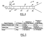
- the rotations of the first and second adjustable 45 degree phase shift sections 14 and 16 may be made using standard rotary joints 34 as shown in block form in Figure 1. It is possible to combine the spacer 26 and the rotary joint 34 into one unit 35 (shown in Figure 4). In the case of a combined spacer and rotary joint, the rotary joint must be sufficiently long enough to isolate the phase shift sections.
- the polarizer 10 of the present invention can be used in both transmit and receive modes.
- the invention will be described herein in the transmit mode when a vertical signal is input at one port of the ortho-mode transducer 18.
- Transmit mode is when a signal, either circular or linear, is received at the ortho-mode transducer 18 and output at the antenna feed 24.
- One skilled in the art will know how to apply the description of the present invention for the receive mode.
- the polarizing elements 30 of the two adjustable 45 degree phase shift sections 14 and 16 are aligned with each other.
- the orientation of the linear signal at the output of the second 45 degree polarizer 16 is the desired polarization direction 36.
- This polarization direction 36 is at an arbitrary angle, ⁇ , from the direction of incident polarization 32, (which is vertical in the present example), at the ortho-mode transducer 18. This is illustrated in the second column of Figure 3.
- the polarizing elements 30 of the first and second 45 degree phase shift sections are at a 45 degree angle with respect to the desired polarization direction 36.
- the polarizing elements 30 of the two adjustable 45 degree phase shift sections 14 and 16 are rotated orthogonal to each other such that their net effect is a zero degree phase shift.
- the polarization is then determined by the 90 degree phase shift section 12 which provides compatibility with circularly polarized signals.
- first and second 45 degree phase shift sections 14 and 16 relative to the 90 degree phase shift section 12 is entirely arbitrary. As long as the first and second 45 degree phase shift sections 14 and 16 are orthogonal to each other, they can be oriented in any direction with respect to the 90 degree phase shift section 12. Depending on the desired circular polarization, right hand circular or left hand circular, the polarizing elements 30 of the 90 degree phase shift section are oriented to either be plus or minus 45 degrees from the direction of incident polarization 32 which is vertical in the present example.
- a linear signal received at the antenna feed 24 and passing through the first and second 45 degree phase shift sections 14 and 16 will be converted to circular polarization.
- the 90 degree phase shift section 12 then converts this polarization to a linear polarization that is oriented to a predetermined port on the ortho-mode transducer 18.
- the predetermined port can be either the through port 20, the orthogonal port 22.
- the 90 degree phase shift section 12 has polarizing elements 30 that are always in a ⁇ 45 degree orientation with respect to the incident polarization direction 32.
- the orientation of the 90 degree phase shift section 12 has the polarizing elements 30 oriented 45 degrees to the direction of the incident polarization 32.
- the first and second 45 degree phase shift sections 14 and 16 are aligned with each other and the polarizing elements 30 are positioned 45 degrees with respect to the desired polarization direction 36.
- vertical polarization is transmitted out the through port 20 and horizontal polarization is transmitted out the orthogonal port 22 of the ortho-mode transducer 18.
- the 90 degree phase shift section 12 remains fixed.
- the first and second 45 degree phase shift sections 14 and 16 remain aligned with each other and the polarizing elements 30 remain oriented 45 degrees from the desired polarization direction 36.
- the desired polarization direction 36 is oriented at an angle, ⁇ , from the incident polarization 32 of the 90 degree phase shift section 12.
- arbitrary linear polarization is transmitted out the through port 20 and orthogonal arbitrary linear polarization is transmitted through the orthogonal port 22.
- the 90 degree phase shift section 12 remains fixed.
- the first 45 degree phase shift section 14 is set to any arbitrary angle, ⁇ relative to the direction of incident polarization 32.
- the second 45 degree phase shift section 16 is oriented such that the polarizing elements 30 are orthogonal to the polarizing elements 30 of the first 45 degree phase shift section 14.
- the linear signal corresponding to right hand circular polarization is transmitted through the through port 20 and the linear signal corresponding to left hand circular polarization is transmitted through the orthogonal port 22.
- an adjustable 90 degree phase shift section 12 it is possible to implement an adjustable 90 degree phase shift section 12 as well.
- the polarizer 10 of the present invention is shown with a combination spacer/rotary joint 35 at the 90 degree phase shift section 12. This reverses the polarization associated with the through and orthogonal ports.
- the 90 degree phase shift section may be rotated 90 degrees and the vertical polarization will be associated with the orthogonal port 22 while the horizontal polarization will be associated with the through port 20.
- spacecraft communication channels have specific bands associated with vertical and horizontal polarizations.
- the adjustable 90 degree phase shift section is useful in spacecraft applications that require channel switching between the through port 20 and the orthogonal port 22.
- Figure 5 is a table 38 outlining the configuration of the polarizer for three polarization scenarios.
- the polarizing elements 30 of the 90 degree phase shift section 12 remain fixed.
- the polarizing elements 30 of the first and second 45 degree phase shift sections 14 and 16 are adjusted according to the desired polarization.
- the polarizing elements 30 of the 45 degree phase shift sections 14 and 16 are at 45 degrees to the incident polarization direction.
- the polarizing elements 30 of the first and second 45 degree phase shift sections 14 and 16 are at 45 degrees to the desired direction.
- the polarizing elements 30 of the first 45 degree section 14 is set at any angle, ⁇ , while the polarizing elements 30 of the second 45 degree section 16 are set to ⁇ + 90 degrees.
- the polarizer 10 of the present invention is capable of receiving a signal and transmitting circular, linear polarization, or a linear polarization of arbitrary orientation. This allows a single feed to receive or transmit any polarization and orientation.
- the polarization of a satellite's antenna may be switched from linear to circular while in orbit by repositioning the first and second adjustable 45 degree phase shift sections 14 and 16.
- the orientation of the linear signal may be modified while a satellite is in orbit.
- the present invention does not require separate feeds or switchable paths to accomplish a reconfigurable polarization.
Landscapes
- Waveguide Aerials (AREA)
- Variable-Direction Aerials And Aerial Arrays (AREA)
- Polarising Elements (AREA)
Applications Claiming Priority (2)
| Application Number | Priority Date | Filing Date | Title |
|---|---|---|---|
| US255122 | 1999-02-22 | ||
| US09/255,122 US6166610A (en) | 1999-02-22 | 1999-02-22 | Integrated reconfigurable polarizer |
Publications (2)
| Publication Number | Publication Date |
|---|---|
| EP1032069A1 true EP1032069A1 (de) | 2000-08-30 |
| EP1032069B1 EP1032069B1 (de) | 2003-12-10 |
Family
ID=22966926
Family Applications (1)
| Application Number | Title | Priority Date | Filing Date |
|---|---|---|---|
| EP00301305A Expired - Lifetime EP1032069B1 (de) | 1999-02-22 | 2000-02-18 | Rekonfigurierbarer Polarisator |
Country Status (4)
| Country | Link |
|---|---|
| US (1) | US6166610A (de) |
| EP (1) | EP1032069B1 (de) |
| CA (1) | CA2298344C (de) |
| ES (1) | ES2211450T3 (de) |
Cited By (2)
| Publication number | Priority date | Publication date | Assignee | Title |
|---|---|---|---|---|
| EP1154510A3 (de) * | 2000-04-14 | 2002-07-10 | RR ELEKTRONISCHE GERÄTE GmbH & Co. KG | Vorrichtung zur Umwandlung zirkular polarisierter Wellen in linear polarisierte Wellen |
| CN110692165A (zh) * | 2017-05-26 | 2020-01-14 | Kvh工业公司 | 具有可切换极化配置的波导装置 |
Families Citing this family (14)
| Publication number | Priority date | Publication date | Assignee | Title |
|---|---|---|---|---|
| US6507952B1 (en) * | 1999-05-25 | 2003-01-14 | Rockwell Collins, Inc. | Passenger entertainment system providing live video/audio programming derived from satellite broadcasts |
| DE10126468B4 (de) * | 2001-05-31 | 2007-07-05 | Eads Deutschland Gmbh | Schlitzantenne |
| US6963253B2 (en) * | 2002-02-15 | 2005-11-08 | University Of Chicago | Broadband high precision circular polarizers and retarders in waveguides |
| US7236681B2 (en) * | 2003-09-25 | 2007-06-26 | Prodelin Corporation | Feed assembly for multi-beam antenna with non-circular reflector, and such an assembly that is field-switchable between linear and circular polarization modes |
| US7053849B1 (en) | 2004-11-26 | 2006-05-30 | Andrew Corporation | Switchable polarizer |
| US20100294989A1 (en) * | 2007-12-28 | 2010-11-25 | Shaffer Ii Edward O | Small scale functional materials |
| EP2225604A1 (de) * | 2007-12-28 | 2010-09-08 | Dow Global Technologies Inc. | Phasenkompensationsfilm mit flüssigkristallmaterial-getränkten polymernanopartikeln |
| US7772940B2 (en) * | 2008-05-16 | 2010-08-10 | Optim Microwave, Inc. | Rotatable polarizer device using a hollow dielectric tube and feed network using the same |
| FR2939971B1 (fr) * | 2008-12-16 | 2011-02-11 | Thales Sa | Ensemble d'excitation compact pour la generation d'une polarisation circulaire dans une antenne et procede d'elaboration d'un tel ensemble d'excitation |
| US8653906B2 (en) | 2011-06-01 | 2014-02-18 | Optim Microwave, Inc. | Opposed port ortho-mode transducer with ridged branch waveguide |
| US8768242B2 (en) * | 2012-03-30 | 2014-07-01 | Harris Corporation | Remote satellite terminal with antenna polarization alignment enforcement and associated methods |
| US8994474B2 (en) | 2012-04-23 | 2015-03-31 | Optim Microwave, Inc. | Ortho-mode transducer with wide bandwidth branch port |
| DE102016112583A1 (de) * | 2016-07-08 | 2018-01-11 | Lisa Dräxlmaier GmbH | Steuerbares Phasenstellglied für elektromagnetische Wellen |
| CN115207619B (zh) * | 2022-07-25 | 2023-04-28 | 中国电子科技集团公司第五十四研究所 | 一种太赫兹波段方向图可重构天线 |
Citations (4)
| Publication number | Priority date | Publication date | Assignee | Title |
|---|---|---|---|---|
| US4141013A (en) * | 1976-09-24 | 1979-02-20 | Hughes Aircraft Company | Integrated circularly polarized horn antenna |
| US4443800A (en) * | 1982-04-12 | 1984-04-17 | The United States Of America As Represented By The Secretary Of The Army | Polarization control element for phased array antennas |
| US4596968A (en) * | 1984-03-02 | 1986-06-24 | Selenia Spazio | Wide frequency band differential phase shifter with constant differential phase shifting |
| US5576668A (en) * | 1995-01-26 | 1996-11-19 | Hughes Aircraft Company | Tandem circular polarizer |
Family Cites Families (6)
| Publication number | Priority date | Publication date | Assignee | Title |
|---|---|---|---|---|
| US2438119A (en) * | 1942-11-03 | 1948-03-23 | Bell Telephone Labor Inc | Wave transmission |
| US2607849A (en) * | 1943-10-02 | 1952-08-19 | Edward M Purcell | Control of polarization in wave guides and wave guide systems |
| US3166724A (en) * | 1961-11-24 | 1965-01-19 | Philip J Allen | Electrical frequency shifter utilizing faraday phase shifter and dual mode coupler with rotatable reflection dipole |
| US3626335A (en) * | 1969-11-10 | 1971-12-07 | Emerson Electric Co | Phase-shifting means |
| US4672334A (en) * | 1984-09-27 | 1987-06-09 | Andrew Corporation | Dual-band circular polarizer |
| JPH0260901A (ja) * | 1988-08-26 | 1990-03-01 | Hitachi Cable Ltd | 高耐油性ゴム成形品 |
-
1999
- 1999-02-22 US US09/255,122 patent/US6166610A/en not_active Expired - Lifetime
-
2000
- 2000-02-09 CA CA002298344A patent/CA2298344C/en not_active Expired - Lifetime
- 2000-02-18 ES ES00301305T patent/ES2211450T3/es not_active Expired - Lifetime
- 2000-02-18 EP EP00301305A patent/EP1032069B1/de not_active Expired - Lifetime
Patent Citations (4)
| Publication number | Priority date | Publication date | Assignee | Title |
|---|---|---|---|---|
| US4141013A (en) * | 1976-09-24 | 1979-02-20 | Hughes Aircraft Company | Integrated circularly polarized horn antenna |
| US4443800A (en) * | 1982-04-12 | 1984-04-17 | The United States Of America As Represented By The Secretary Of The Army | Polarization control element for phased array antennas |
| US4596968A (en) * | 1984-03-02 | 1986-06-24 | Selenia Spazio | Wide frequency band differential phase shifter with constant differential phase shifting |
| US5576668A (en) * | 1995-01-26 | 1996-11-19 | Hughes Aircraft Company | Tandem circular polarizer |
Cited By (3)
| Publication number | Priority date | Publication date | Assignee | Title |
|---|---|---|---|---|
| EP1154510A3 (de) * | 2000-04-14 | 2002-07-10 | RR ELEKTRONISCHE GERÄTE GmbH & Co. KG | Vorrichtung zur Umwandlung zirkular polarisierter Wellen in linear polarisierte Wellen |
| CN110692165A (zh) * | 2017-05-26 | 2020-01-14 | Kvh工业公司 | 具有可切换极化配置的波导装置 |
| EP3631891B1 (de) * | 2017-05-26 | 2023-06-21 | KVH Industries, Inc. | Wellenleitervorrichtung mit schaltbaren polarisationskonfigurationen |
Also Published As
| Publication number | Publication date |
|---|---|
| EP1032069B1 (de) | 2003-12-10 |
| ES2211450T3 (es) | 2004-07-16 |
| CA2298344A1 (en) | 2000-08-22 |
| CA2298344C (en) | 2002-10-01 |
| US6166610A (en) | 2000-12-26 |
Similar Documents
| Publication | Publication Date | Title |
|---|---|---|
| US6166610A (en) | Integrated reconfigurable polarizer | |
| US4308541A (en) | Antenna feed system for receiving circular polarization and transmitting linear polarization | |
| EP4135125B1 (de) | Phasengesteuertes gruppenantennensystem | |
| US3827051A (en) | Adjustable polarization antenna system | |
| US6931245B2 (en) | Downconverter for the combined reception of linear and circular polarization signals from collocated satellites | |
| CA2424101C (en) | Efficiently generating selectable antenna polarization | |
| US5933113A (en) | Simultaneous multibeam and frequency active photonic array radar apparatus | |
| CA2040318A1 (en) | Feed network for a dual circular and dual linear polarization antenna | |
| JP2009517904A (ja) | 円偏波共用アンテナ・アレイ | |
| US4728960A (en) | Multifunctional microstrip antennas | |
| KR101847133B1 (ko) | 단일의 이중편파 복사소자에 의한 4중편파 안테나 장치 | |
| US6816026B2 (en) | Orthogonal polarization and frequency selectable waveguide using rotatable waveguide sections | |
| JP2000349547A (ja) | アンテナ給電装置 | |
| US20160344083A1 (en) | Dual-channel polarization correction | |
| US12531337B2 (en) | Massive MIMO beamforming antenna with improved gain | |
| JP3036159B2 (ja) | 偏波共用アンテナ | |
| US10033099B2 (en) | Dual-polarized, dual-band, compact beam forming network | |
| JPH07162227A (ja) | 偏波共用アンテナシステム | |
| US9947978B1 (en) | Orthomode transducer | |
| JP4903100B2 (ja) | 導波管形電力合成分配器およびそれを用いたアレーアンテナ装置 | |
| WO2000028621A1 (en) | Cavity-driven antenna system | |
| US10615472B2 (en) | Feed polarizer step twist switch | |
| JPS6014501A (ja) | 偏分波器 | |
| AU768273B2 (en) | Antenna apparatus in mobile communication system | |
| US20240396191A1 (en) | Contactless rotary joint for connecting waveguides |
Legal Events
| Date | Code | Title | Description |
|---|---|---|---|
| PUAI | Public reference made under article 153(3) epc to a published international application that has entered the european phase |
Free format text: ORIGINAL CODE: 0009012 |
|
| AK | Designated contracting states |
Kind code of ref document: A1 Designated state(s): ES FR GB IT |
|
| AX | Request for extension of the european patent |
Free format text: AL;LT;LV;MK;RO;SI |
|
| 17P | Request for examination filed |
Effective date: 20010202 |
|
| AKX | Designation fees paid |
Free format text: ES FR GB IT |
|
| 17Q | First examination report despatched |
Effective date: 20010409 |
|
| GRAH | Despatch of communication of intention to grant a patent |
Free format text: ORIGINAL CODE: EPIDOS IGRA |
|
| GRAA | (expected) grant |
Free format text: ORIGINAL CODE: 0009210 |
|
| GRAS | Grant fee paid |
Free format text: ORIGINAL CODE: EPIDOSNIGR3 |
|
| AK | Designated contracting states |
Kind code of ref document: B1 Designated state(s): ES FR GB IT |
|
| REG | Reference to a national code |
Ref country code: GB Ref legal event code: FG4D |
|
| REG | Reference to a national code |
Ref country code: ES Ref legal event code: FG2A Ref document number: 2211450 Country of ref document: ES Kind code of ref document: T3 |
|
| ET | Fr: translation filed | ||
| PLBE | No opposition filed within time limit |
Free format text: ORIGINAL CODE: 0009261 |
|
| STAA | Information on the status of an ep patent application or granted ep patent |
Free format text: STATUS: NO OPPOSITION FILED WITHIN TIME LIMIT |
|
| RAP2 | Party data changed (patent owner data changed or rights of a patent transferred) |
Owner name: THE BOEING COMPANY |
|
| 26N | No opposition filed |
Effective date: 20040913 |
|
| REG | Reference to a national code |
Ref country code: GB Ref legal event code: 732E |
|
| REG | Reference to a national code |
Ref country code: FR Ref legal event code: PLFP Year of fee payment: 17 |
|
| REG | Reference to a national code |
Ref country code: FR Ref legal event code: PLFP Year of fee payment: 18 |
|
| REG | Reference to a national code |
Ref country code: FR Ref legal event code: PLFP Year of fee payment: 19 |
|
| PGFP | Annual fee paid to national office [announced via postgrant information from national office to epo] |
Ref country code: IT Payment date: 20190222 Year of fee payment: 20 Ref country code: ES Payment date: 20190301 Year of fee payment: 20 Ref country code: GB Payment date: 20190227 Year of fee payment: 20 |
|
| PGFP | Annual fee paid to national office [announced via postgrant information from national office to epo] |
Ref country code: FR Payment date: 20190225 Year of fee payment: 20 |
|
| REG | Reference to a national code |
Ref country code: GB Ref legal event code: PE20 Expiry date: 20200217 |
|
| PG25 | Lapsed in a contracting state [announced via postgrant information from national office to epo] |
Ref country code: GB Free format text: LAPSE BECAUSE OF EXPIRATION OF PROTECTION Effective date: 20200217 |
|
| REG | Reference to a national code |
Ref country code: ES Ref legal event code: FD2A Effective date: 20200806 |
|
| PG25 | Lapsed in a contracting state [announced via postgrant information from national office to epo] |
Ref country code: ES Free format text: LAPSE BECAUSE OF EXPIRATION OF PROTECTION Effective date: 20200219 |