EP1032168A2 - Kanalschätzung unter Verwendung von auf lagrangschen Polynomen basierter Interpolierung - Google Patents
Kanalschätzung unter Verwendung von auf lagrangschen Polynomen basierter Interpolierung Download PDFInfo
- Publication number
- EP1032168A2 EP1032168A2 EP00301165A EP00301165A EP1032168A2 EP 1032168 A2 EP1032168 A2 EP 1032168A2 EP 00301165 A EP00301165 A EP 00301165A EP 00301165 A EP00301165 A EP 00301165A EP 1032168 A2 EP1032168 A2 EP 1032168A2
- Authority
- EP
- European Patent Office
- Prior art keywords
- estimate
- channel
- channel distortion
- data blocks
- distortion
- Prior art date
- Legal status (The legal status is an assumption and is not a legal conclusion. Google has not performed a legal analysis and makes no representation as to the accuracy of the status listed.)
- Withdrawn
Links
- 238000000034 method Methods 0.000 claims abstract description 43
- 238000012884 algebraic function Methods 0.000 claims 3
- 230000003111 delayed effect Effects 0.000 claims 2
- 230000005540 biological transmission Effects 0.000 abstract description 8
- 238000012935 Averaging Methods 0.000 description 11
- 238000010586 diagram Methods 0.000 description 5
- 230000001427 coherent effect Effects 0.000 description 3
- 238000004891 communication Methods 0.000 description 3
- 238000003780 insertion Methods 0.000 description 3
- 230000037431 insertion Effects 0.000 description 3
- 230000000694 effects Effects 0.000 description 2
- 238000002474 experimental method Methods 0.000 description 2
- 230000010363 phase shift Effects 0.000 description 2
- 230000006978 adaptation Effects 0.000 description 1
- 230000004075 alteration Effects 0.000 description 1
- 238000013459 approach Methods 0.000 description 1
- 230000001934 delay Effects 0.000 description 1
- 238000005516 engineering process Methods 0.000 description 1
- 239000000284 extract Substances 0.000 description 1
- 238000012545 processing Methods 0.000 description 1
- 238000011084 recovery Methods 0.000 description 1
- 238000001228 spectrum Methods 0.000 description 1
- 230000003068 static effect Effects 0.000 description 1
- 238000006467 substitution reaction Methods 0.000 description 1
Images

Classifications
-
- H—ELECTRICITY
- H04—ELECTRIC COMMUNICATION TECHNIQUE
- H04L—TRANSMISSION OF DIGITAL INFORMATION, e.g. TELEGRAPHIC COMMUNICATION
- H04L25/00—Baseband systems
- H04L25/02—Details ; arrangements for supplying electrical power along data transmission lines
- H04L25/03—Shaping networks in transmitter or receiver, e.g. adaptive shaping networks
- H04L25/03006—Arrangements for removing intersymbol interference
-
- H—ELECTRICITY
- H04—ELECTRIC COMMUNICATION TECHNIQUE
- H04L—TRANSMISSION OF DIGITAL INFORMATION, e.g. TELEGRAPHIC COMMUNICATION
- H04L25/00—Baseband systems
- H04L25/02—Details ; arrangements for supplying electrical power along data transmission lines
- H04L25/0202—Channel estimation
- H04L25/0224—Channel estimation using sounding signals
- H04L25/0228—Channel estimation using sounding signals with direct estimation from sounding signals
- H04L25/023—Channel estimation using sounding signals with direct estimation from sounding signals with extension to other symbols
- H04L25/0232—Channel estimation using sounding signals with direct estimation from sounding signals with extension to other symbols by interpolation between sounding signals
- H04L25/0234—Channel estimation using sounding signals with direct estimation from sounding signals with extension to other symbols by interpolation between sounding signals by non-linear interpolation
Definitions
- This invention is related to digital signal processing, particularly to compensate for channel distortion in digital mobile radio transmission.
- Digital mobile radio communication is plagued by distortion in the transmission channel.
- the Doppler effect due to a moving transmitter or receiver and multiple paths of propagation due to reflection are two principal causes of this distortion. Compensating for this distortion is particularly important in a Direct Sequence Code Division Multiple Access (DS-CDMA) system.
- DS-CDMA Direct Sequence Code Division Multiple Access
- Accurate channel distortion compensation enables the DS-CDMA system to operate in a coherent delay-locked tracking loop (DLL) mode which has numerous advantages over a noncoherent delay-locked tracking mode.
- DLL coherent delay-locked tracking loop
- Coherent DLL mode of operation reduces the background noise by as much a 3 dB compared to the noncoherent DLL mode and, for the same BER (Bit Error Rate), requires less transmitted power output.
- Distortion in a digital mobile radio channel is predominately manifested as amplitude and phase variation of the channel gain. If the channel gain can be accurately estimated, then good compensation for the channel distortion may be achieved.
- One approach to obtaining a good estimate of the channel gain is based on insertion of known symbols at regular intervals in the data stream. When these symbols are recovered in the receiver any deviation from their known values is taken to be caused by the time-varying channel gain. From these deviations, the channel gain may be estimated.
- Various methods are known for such insertion and recovery of known symbols, but all are subject to limitations. For example, one such estimation method uses only a few symbols at a time which makes this method vulnerable to noise.
- Another exemplary method uses an experimental method to determine a fixed set of estimation formulae. These fixed estimation formulae do not adjust to the changing conditions that exist during operation in a real channel.
- the present invention provides an efficient method of estimating and compensating for the rapid amplitude and phase fluctuations in a digital mobile radio transmission system based on the insertion of known pilot symbols periodically into the data stream. Multiple consecutive symbols are inserted and the consecutive received values averaged to overcome random noise. These averaged values provide samples of the complex, random channel gain. These samples are used for interpolation by the Lagrange polynomial method to yield the values of amplitude and phase distribution undergone by each channel data symbol.
- the invention is directed to an improved method for determining channel gain in a wireless communications system where data is transmitted in a digital mode.
- Application of the methodology of the invention is described hereafter in terms of a preferred embodiment based on a DS-CDMA wireless system. It will, however, be apparent to those skilled in the art that the inventive methodology may be applied for a variety of digital wireless systems.
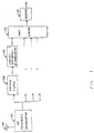
- FIG. 1 is a block diagram of a typical DS-CDMA receiver system of the present art.
- An antenna 100 receives a spread-spectrum radio frequency (RF) signal.
- a typical carrier frequency is 2 gigahertz (GHz) with a typical bandwidth of 5 megahertz (MHz).
- An RF receiver/demodulator 102 converts down from the carrier frequency.
- the result is an analog baseband signal, modulated by an encoded data stream, typically at 32 kilobits per second (kbps), and re-modulated by a spreading signal, typically at 4.096 megachips per second (Mcps).
- Chip is the standard term for one cycle time of a spreading signal.
- a matched filter 104 removes the spreading signal by correlation with the phase of the spreading signal.
- the remaining analog baseband signal is processed by a channel estimation and compensation processor 106 to produce an estimate of the encoded data.
- the RF signal received at antenna 100 will generally include the superposition of multiple images of the source transmission -- representing different paths of propagation with different delays -- multiple instances of the filter 104 and compensation processor 106 may be used to extract an estimate of the encoded data stream from each of several of the strongest paths of propagation.
- a RAKE combiner 108 linearly combines these estimates to produce a higher confidence combined estimate of the original encoded data.
- a decoder 110 extracts the original data transmission.
- the signal at the input of a channel estimation and compensation processor 106 is a modulated baseband signal distorted by propagation though the channel and by random noise.
- Data modulation may be based on any known methodology, but for purposes of the illustrative embodiment of the invention is taken to be quadrature phase shift keying (QPSK), which represents a data stream as a sequence of four-state symbols.
- QPSK quadrature phase shift keying
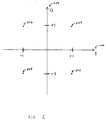
- Figure 2 illustrates the four QPSK symbol states.
- An in-phase baseband carrier signal I 200 is set to a + 1 state or a -1 state, the latter being 180 degrees away from a + 1 state.
- a quadrature baseband carrier signal Q 202 is set to a + 1 state or a - 1 state, the latter being 180 degrees away from a + 1 state.
- I and Q signals are combined to produce a two-dimensional signal with the four states 204 , 206 , 208 , and 210 shown in Figure 2.
- a time sequence of two-dimensional signals like those of a QPSK modulation may be represented as a complex function of time.
- complex time function z ( t ) be the originally transmitted QPSK-modulated baseband signal.
- Equation 2 can be rearranged to solve for c & ( t ) and accordingly the approximate value of the channel distortion at any instant may be calculated from the values of the received signal and the original signal at that instant. If known pilot symbols with values p are inserted in the original signal at specific points in time, then the original signal is known at those points and the value of the channel distortion at those points may be calculated from the value of the received signal at those points and the original pilot signal values. The "channel estimation" is then derived as an interpolation of these sample values of the channel function at the pilot signal points.
- Figure 3 shows a data stream 302 divided into ordered, consecutive blocks of M symbols each.
- the period of transmission of each block is T B .
- one or more known pilot symbols are inserted in the data stream 302 .
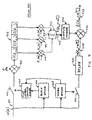
- Figure 4 is a diagram of a channel estimation and compensation processor that uses inserted pilot symbols according to the method of Sampei and Sunaga (S. Sampei and T. Sunaga, "Rayleigh Fading Compensation for QAM in Land Mobile Radio Communications", IEEE Transactions on Vehicular Technology , Vol. 42, No. 2, May 1993, pp. 137-147).
- An input analog baseband signal u ( t ) 400 is provided to and processed by a symbol synchronization module 408 and a block synchronization module 406 .
- Outputs of the symbol and block synchronization modules are processed to produce a pilot symbol sample clock 404 that controls an analog-to-digital sample circuit 402 (depicted with a switch-like symbol), which operates to cause digital values of pilot symbol signals to be sent to the complex multiplier 411 .
- the output of the complex multiplier 411 represents an estimate of the channel gain at the time of a particular pilot symbol. This estimate is sent to delay line 412 .
- the symbol synchronization module 408 also controls an analog-to-digital sample circuit 410 (depicted with a switch-like symbol) that operates to cause digital values of the input baseband signal u ( t ) 400 at each symbol time to be stored in a delay line 426 .
- pilot symbols are sampled at t -1.0 , t 0.0 , and t 1.0 , - - i.e., there is one pilot symbol at the beginning of each block, and the symbols from blocks -1, 0, and 1 are used for channel estimation.
- complex multiplier 411 For each input pilot symbol sample u ( t k.0 ), complex multiplier 411 computes where p k is the known value of the pilot symbol at the beginning of data block k .
- Complex multipliers 414 , 416 , and 418 are used to multiply the channel gain estimates in the delay line 412 by appropriate weighting coefficients ⁇ 1 ( m ), ⁇ 0 ( m ), and ⁇ 1 ( m ), and the multiplier results are summed in complex adder 420 .
- ⁇ 1 ( m ) is determined empirically according to known methods.
- the resulting sum 422 (at output of adder 420 ) is therefore represented algebraically as: with T s defined to be the symbol period.
- Equation 5 constitutes a second-order Gaussian interpolation of the value of the estimated channel gain at the symbol sample time of the m th symbol in an arbitrarily selected block 0 based on the estimated values of the channel gain at the pilot symbol sample times stored in delay line 412 .
- the inverse of resulting sum 422 is then computed by complex multiplicative inverter 424 .
- a baseband symbol sample 428 is generated by delay line 426 , where the delay is established to synchronize that baseband symbol sample with the computation of the estimated channel gain at the same sample time.
- Complex multiplier 430 then multiplies the output of inverter 424 with symbol sample 428 to generate an estimate of an original data symbol 432 in accordance with Equation 2.
- a channel estimation and compensation processor uses inserted pilot symbols according to the method of Andoh, Sawahashi, and Adachi (See H. Andoh, M. Sawahashi, and F. Adachi, "Channel Estimation Using Time Multiplexed Pilot Symbols for Coherent Rake Combining for DS-CDMAS Mobile Radio", (IEEE, PIMRC'97, Helsinki, Finland, September 1-4, 1997), that method being known as weighted multi-slot averaging (WMSA).
- WMSA weighted multi-slot averaging
- Outputs of the symbol and block synchronization modules are processed to produce a pilot symbol sample clock 504 that controls an analog-to-digital sample circuit 402 (depicted with a switch-like symbol) to cause digital values of pilot symbol signals to be sent to complex multiplier 511 .
- the output of complex multiplier 511 represents an estimate of the channel gain at the time of a particular pilot symbol. This estimate is sent to delay line 512 .
- the symbol synchronization module 408 also controls an analog-to-digital sample circuit 410 (depicted with a switch-like symbol) that operates to cause digital values of the input baseband signal u ( t ) 500 at each pilot symbol time to be stored in a delay line 526 .
- Complex averaging modules 534 are used to average the four channel-gain estimates associated with four consecutive pilot symbols at the start of each block that are stored in the delay line 512 . This averaging minimizes the error associated with the noise term of Equation 4. The noise-term error is, of course, greater for the method described in conjunction with Figure 4, which does not use such averaging.
- Complex multipliers 514 , 515 , 516 , 517 , 518 , and 519 are used to multiply the outputs of averaging modules 534 by appropriate weighting coefficients ⁇ -2 , ⁇ -1 , ⁇ -0 , ⁇ -1 , ⁇ 2 , and ⁇ 3 , and the multiplier results are summed in complex adder 520 .
- the resulting sum 522 (at the output of adder 520 )is therefore represented algebraically as: From this equation, it can be seen that the channel gain estimate c & ( t 0.0 ) is used for all symbol samples times in block 0, regardless of the value of m . Also note that the ⁇ coefficients are independent of m.
- these coefficients are derived empirically by adjusting them during experiments to achieve the best performance for a particular set of actual channel conditions. However, these coefficients are held constant during actual operation -- i.e ., they do not adjust dynamically to changing conditions
- the inverse of resulting sum 522 is then computed by complex multiplicative inverter 424 .
- a baseband symbol sample 528 is generated by delay line 526 , where the delay is established to synchronize that baseband symbol sample with the computation of the estimated channel gain at the same sample time.
- Complex multiplier 430 then multiplies the output of inverter 424 with symbol sample 528 to generate an estimate of an original data symbol 532 in accordance with Equation 2.
- this WMSA method of estimating channel gain has better noise tolerance than the first method because of averaging of consecutive pilot symbols, but it uses static formulae for interpolation and does not dynamically adjust to changing channel conditions.
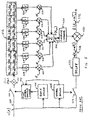
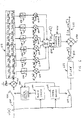
- An input baseband signal u ( t ) 500 is processed by a symbol synchronization module 408 and a block synchronization module 406 .
- Outputs of the symbol and block timing modules are processed to produce a pilot symbol sample clock 504 that controls an analog-to-digital sample circuit 402 (depicted with a switch-like symbol) to cause digital values of pilot symbol signals to be sent to the complex multiplier 511 .
- the output of the complex multiplier 511 represents an estimate of the channel gain at the time of a particular channel symbol. This estimate is sent to the delay line 512 .
- the symbol synchronization module 408 also controls an analog-to-digital sample circuit 410 (depicted with a switch-like symbol) that operates to cause digital values of the input baseband signal u ( t ) 500 at each pilot symbol time to be stored in a delay line 526 .
- Complex averaging modules 534 are used to average the four channel gain estimates associated with the four consecutive pilot symbols at the start of each block that are stored in the delay line 512 . This averaging operates to minimize the error associated with the noise term of Equation 4. It should be understood, as well, that the use of more than four symbols per block would effect an even better cancellation of the noise error. Accordingly, while the preferred embodiment of the inventive methodology is based on the use of four symbols per block, that method also contemplates the use of a greater number of symbols.
- Complex multipliers 614 , 615 , 616 , 617 , 618 , and 619 are used to multiply the outputs of averaging modules 534 by appropriate weighting coefficients ⁇ -2 ( m ), ⁇ -1 ( m ), ⁇ 0 ( m ), ⁇ -1 ( m ), ⁇ 2 ( m ), and ⁇ 3 ( m ), and the multiplier results are summed in complex adder 520 .
- the resulting sum 622 (at the output of adder 520 ) is therefore represented algebraically as:
- Equations 8 through 14 constitute a fifth-order (six point) Lagrange polynomial interpolation of the value of the estimated channel gain at the symbol sample time of any symbol in block 0 from the estimated values of the channel gain at the pilot symbol sample times stored in delay line 512 .
- such interpolation may be made with a Lagrange interpolation of any order ( r - 1), using the corresponding r blocks centered on block 0, and using any number P ⁇ N of pilot symbols at the beginning of each block.
- the resulting channel gain estimates are: where -0.5( r -2) ⁇ k ⁇ 0.5 r for even r . and -0.5( r -1) ⁇ k ⁇ 0.5 ( r -1) for odd r .
- the inverse of resulting sum 622 is then computed by complex multiplicative inverter 424 .
- a baseband symbol sample 528 is generated by delay line 526 , where the delay is established to synchronize that baseband symbol sample with the computation of the estimated channel gain at the same sample time.
- Complex multiplier 430 then multiplies the output of inverter 424 with symbol sampl e 528 to generate an estimate of an original data symbol 632 in accordance with Equation 2.
- a channel estimation methodology has been described that operates on one or more consecutive pilot symbols per data block and incorporates Lagrange interpolation of the estimated channel gain between pilot symbols.
- the parameters of this interpolation adjust dynamically to changing channel conditions.
Landscapes
- Engineering & Computer Science (AREA)
- Power Engineering (AREA)
- Computer Networks & Wireless Communication (AREA)
- Signal Processing (AREA)
- Physics & Mathematics (AREA)
- Nonlinear Science (AREA)
- Cable Transmission Systems, Equalization Of Radio And Reduction Of Echo (AREA)
- Monitoring And Testing Of Transmission In General (AREA)
- Transmitters (AREA)
- Digital Transmission Methods That Use Modulated Carrier Waves (AREA)
Applications Claiming Priority (2)
| Application Number | Priority Date | Filing Date | Title |
|---|---|---|---|
| US255088 | 1994-06-07 | ||
| US25508899A | 1999-02-22 | 1999-02-22 |
Publications (1)
| Publication Number | Publication Date |
|---|---|
| EP1032168A2 true EP1032168A2 (de) | 2000-08-30 |
Family
ID=22966785
Family Applications (1)
| Application Number | Title | Priority Date | Filing Date |
|---|---|---|---|
| EP00301165A Withdrawn EP1032168A2 (de) | 1999-02-22 | 2000-02-15 | Kanalschätzung unter Verwendung von auf lagrangschen Polynomen basierter Interpolierung |
Country Status (7)
| Country | Link |
|---|---|
| EP (1) | EP1032168A2 (de) |
| JP (1) | JP2000253080A (de) |
| KR (1) | KR20000076706A (de) |
| CN (1) | CN1265544A (de) |
| AU (1) | AU1639800A (de) |
| BR (1) | BR0000847A (de) |
| CA (1) | CA2298273A1 (de) |
Cited By (7)
| Publication number | Priority date | Publication date | Assignee | Title |
|---|---|---|---|---|
| WO2003030402A1 (en) * | 2001-10-01 | 2003-04-10 | Ericsson, Inc. | Communications methods, apparatus and computer programs products for channel characterization |
| KR100394335B1 (ko) * | 2000-03-31 | 2003-08-06 | 가부시끼가이샤 도시바 | 수신장치 |
| EP1347608A1 (de) * | 2002-03-21 | 2003-09-24 | TELECOM ITALIA S.p.A. | Interpolation zur Verwendung bei Kanalschätzung |
| GB2351879B (en) * | 1999-04-21 | 2003-10-08 | Infineon Technologies Corp | Cellular telecommunications systems |
| US7292555B2 (en) | 2000-11-21 | 2007-11-06 | Huawei Technologies Co., Ltd. | Apparatus and method for enhancing channel utilization ratio in a CDMA |
| US7965796B2 (en) | 2002-02-27 | 2011-06-21 | Freescale Semiconductor, Inc. | Channel estimation in a radio receiver |
| CN115604067A (zh) * | 2022-10-27 | 2023-01-13 | 中国星网网络应用有限公司(Cn) | 一种信号的定时同步方法、装置、电子设备及存储介质 |
Families Citing this family (4)
| Publication number | Priority date | Publication date | Assignee | Title |
|---|---|---|---|---|
| EP1408621A4 (de) * | 2001-07-13 | 2006-08-30 | Kawasaki Microelectronics Inc | Cdma-empfangsvorrichtung und cdma-empfangsverfahren |
| US6441786B1 (en) * | 2001-07-20 | 2002-08-27 | Motorola, Inc. | Adaptive antenna array and method for control thereof |
| JP5261173B2 (ja) * | 2006-06-01 | 2013-08-14 | 直樹 末広 | マルチパス特性推定方法及び装置、受信方法並びに受信信号補正方法及び装置 |
| CN115242256B (zh) * | 2022-07-21 | 2024-01-02 | 珠海泰芯半导体有限公司 | Iq通道的校正方法、电子设备和计算机存储介质 |
-
2000
- 2000-02-08 CA CA002298273A patent/CA2298273A1/en not_active Abandoned
- 2000-02-14 AU AU16398/00A patent/AU1639800A/en not_active Abandoned
- 2000-02-15 EP EP00301165A patent/EP1032168A2/de not_active Withdrawn
- 2000-02-18 BR BR0000847-8A patent/BR0000847A/pt not_active Application Discontinuation
- 2000-02-21 CN CN00102350A patent/CN1265544A/zh active Pending
- 2000-02-22 JP JP2000044007A patent/JP2000253080A/ja active Pending
- 2000-02-22 KR KR1020000008474A patent/KR20000076706A/ko not_active Withdrawn
Cited By (10)
| Publication number | Priority date | Publication date | Assignee | Title |
|---|---|---|---|---|
| GB2351879B (en) * | 1999-04-21 | 2003-10-08 | Infineon Technologies Corp | Cellular telecommunications systems |
| KR100394335B1 (ko) * | 2000-03-31 | 2003-08-06 | 가부시끼가이샤 도시바 | 수신장치 |
| US7292555B2 (en) | 2000-11-21 | 2007-11-06 | Huawei Technologies Co., Ltd. | Apparatus and method for enhancing channel utilization ratio in a CDMA |
| WO2003030402A1 (en) * | 2001-10-01 | 2003-04-10 | Ericsson, Inc. | Communications methods, apparatus and computer programs products for channel characterization |
| US7236514B2 (en) | 2001-10-01 | 2007-06-26 | Ericsson, Inc. | Communications methods, apparatus and computer program products using gain multipliers |
| US7965796B2 (en) | 2002-02-27 | 2011-06-21 | Freescale Semiconductor, Inc. | Channel estimation in a radio receiver |
| EP1347608A1 (de) * | 2002-03-21 | 2003-09-24 | TELECOM ITALIA S.p.A. | Interpolation zur Verwendung bei Kanalschätzung |
| WO2003081862A1 (en) * | 2002-03-21 | 2003-10-02 | Telecom Italia S.P.A. | Interpolation for use in channel estimation |
| US7450663B2 (en) | 2002-03-21 | 2008-11-11 | Telecom Italia S.P.A. | Interpolation for use in channel estimation |
| CN115604067A (zh) * | 2022-10-27 | 2023-01-13 | 中国星网网络应用有限公司(Cn) | 一种信号的定时同步方法、装置、电子设备及存储介质 |
Also Published As
| Publication number | Publication date |
|---|---|
| BR0000847A (pt) | 2000-12-19 |
| JP2000253080A (ja) | 2000-09-14 |
| AU1639800A (en) | 2000-08-24 |
| CA2298273A1 (en) | 2000-08-22 |
| CN1265544A (zh) | 2000-09-06 |
| KR20000076706A (ko) | 2000-12-26 |
Similar Documents
| Publication | Publication Date | Title |
|---|---|---|
| US5694388A (en) | CDMA demodulator and demodulation method | |
| EP0715440B1 (de) | Synchrondetektorschaltung und synchronisierungsmethode für einen digitalsignalempfänger | |
| US6956895B2 (en) | Method and arrangement for reducing frequency offset in a radio receiver | |
| EP1135865B1 (de) | Digitale empfänger und empfangsverfahren zur skalierung der relativen stärken der verkehrs-und pilotenkanäle während sanften weiterreichungsverfahren | |
| US5659573A (en) | Method and apparatus for coherent reception in a spread-spectrum receiver | |
| US9100250B2 (en) | Pre-phase error correction | |
| US7301993B2 (en) | Channel estimation in a spread spectrum receiver | |
| EP1063779B1 (de) | Einrichtung zum Umkehrspreitzen des Spectrum, Einrichtung zur Zeitpunktdetedtion, Kanalschätzer, Frequensmessung und automatische Frequenzregelung | |
| WO2002032067A1 (en) | Method for automatic frequency control | |
| AU1639800A (en) | Method and system for compensation of channel distortion using lagrange polynomial interpolation | |
| EP1913748B1 (de) | Erweiterte qpsk- oder dqpsk-datendemodulation für wellenformen eines direct sequence spreading (dss)-systems unter verwendung orthogonaler oder quasi-orthogonaler spreizsequenzen | |
| JP3029030B2 (ja) | パイロット信号を含む受信信号の復調方法およびその装置 | |
| US20020159505A1 (en) | Receiver and receiving method fro spread spectrum communication | |
| US6785351B1 (en) | Method and system for Doppler frequency estimation | |
| US7181185B2 (en) | Apparatus and method for performing channel estimations using non-linear filter | |
| US7584410B2 (en) | Frequency error detector and combiner in receiving end of mobile communication system | |
| US6775341B2 (en) | Time recovery circuit and method for synchronizing timing of a signal in a receiver to timing of the signal in a transmitter | |
| JP3472768B2 (ja) | 最大ドップラー周波数推定装置および無線通信装置 | |
| JPWO1996000471A1 (ja) | Cdma復調回路および復調方法 | |
| HK1095932B (en) | Method for digital code tracking loop, radio transmission controller and transmitting spread spectrum signals | |
| HK1095932A1 (en) | Method for digital code tracking loop, radio transmission controller and transmitting spread spectrum signals |
Legal Events
| Date | Code | Title | Description |
|---|---|---|---|
| PUAI | Public reference made under article 153(3) epc to a published international application that has entered the european phase |
Free format text: ORIGINAL CODE: 0009012 |
|
| AK | Designated contracting states |
Kind code of ref document: A2 Designated state(s): AT BE CH CY DE DK ES FI FR GB GR IE IT LI LU MC NL PT SE |
|
| AX | Request for extension of the european patent |
Free format text: AL;LT;LV;MK;RO;SI |
|
| STAA | Information on the status of an ep patent application or granted ep patent |
Free format text: STATUS: THE APPLICATION HAS BEEN WITHDRAWN |
|
| 18W | Application withdrawn |
Withdrawal date: 20021030 |