EP1032209A2 - Vorrichtung und Verfahren zur Überwachung der Umgebung eines Fahrzeuges - Google Patents
Vorrichtung und Verfahren zur Überwachung der Umgebung eines Fahrzeuges Download PDFInfo
- Publication number
- EP1032209A2 EP1032209A2 EP00103420A EP00103420A EP1032209A2 EP 1032209 A2 EP1032209 A2 EP 1032209A2 EP 00103420 A EP00103420 A EP 00103420A EP 00103420 A EP00103420 A EP 00103420A EP 1032209 A2 EP1032209 A2 EP 1032209A2
- Authority
- EP
- European Patent Office
- Prior art keywords
- vehicle
- picture
- monitoring
- improper
- circumference
- Prior art date
- Legal status (The legal status is an assumption and is not a legal conclusion. Google has not performed a legal analysis and makes no representation as to the accuracy of the status listed.)
- Granted
Links
- 238000012544 monitoring process Methods 0.000 title claims abstract description 96
- 238000000034 method Methods 0.000 title claims abstract description 31
- 238000003384 imaging method Methods 0.000 claims description 28
- 238000012545 processing Methods 0.000 claims description 16
- 230000006870 function Effects 0.000 description 11
- 238000010586 diagram Methods 0.000 description 2
- 238000012986 modification Methods 0.000 description 2
- 230000004048 modification Effects 0.000 description 2
- 230000003287 optical effect Effects 0.000 description 2
- 230000004913 activation Effects 0.000 description 1
- 230000006866 deterioration Effects 0.000 description 1
- 238000011161 development Methods 0.000 description 1
- 238000006073 displacement reaction Methods 0.000 description 1
- 230000000694 effects Effects 0.000 description 1
- 230000001747 exhibiting effect Effects 0.000 description 1
- 230000002779 inactivation Effects 0.000 description 1
- 238000004519 manufacturing process Methods 0.000 description 1
- 238000011084 recovery Methods 0.000 description 1
Images
Classifications
-
- B—PERFORMING OPERATIONS; TRANSPORTING
- B60—VEHICLES IN GENERAL
- B60Q—ARRANGEMENT OF SIGNALLING OR LIGHTING DEVICES, THE MOUNTING OR SUPPORTING THEREOF OR CIRCUITS THEREFOR, FOR VEHICLES IN GENERAL
- B60Q1/00—Arrangement of optical signalling or lighting devices, the mounting or supporting thereof or circuits therefor
- B60Q1/26—Arrangement of optical signalling or lighting devices, the mounting or supporting thereof or circuits therefor the devices being primarily intended to indicate the vehicle, or parts thereof, or to give signals, to other traffic
- B60Q1/50—Arrangement of optical signalling or lighting devices, the mounting or supporting thereof or circuits therefor the devices being primarily intended to indicate the vehicle, or parts thereof, or to give signals, to other traffic for indicating other intentions or conditions, e.g. request for waiting or overtaking
- B60Q1/52—Arrangement of optical signalling or lighting devices, the mounting or supporting thereof or circuits therefor the devices being primarily intended to indicate the vehicle, or parts thereof, or to give signals, to other traffic for indicating other intentions or conditions, e.g. request for waiting or overtaking for indicating emergencies
-
- H—ELECTRICITY
- H04—ELECTRIC COMMUNICATION TECHNIQUE
- H04N—PICTORIAL COMMUNICATION, e.g. TELEVISION
- H04N7/00—Television systems
- H04N7/18—Closed-circuit television [CCTV] systems, i.e. systems in which the video signal is not broadcast
Definitions
- the present invention relates to a vehicle's circumference monitoring method which is employed to determine whether or not there exists an obstacle (or obstacles) around a vehicle owing to the application of a designated image processing on the circumferential picture taken by using an imaging unit installed in the vehicle, for example, a CCD camera.
- a vehicle's circumference monitoring method which can provide the result of monitoring the circumference of the owner's vehicle with high-leveled reliability and also related to a vehicle's circumference monitoring apparatus adopting the vehicle's circumference monitoring method.
- Japanese Patent Application Laid-open Publication No. 7-5076 9 discloses a vehicle's circumference monitoring method which may be used when it is required to monitor the existence of the obstacle (or obstacles) around the vehicle. According to the monitoring method, it has been carried out to apply the designated image processing on the picture around the vehicle brought by the imaging unit, for example, the CCD camera.
- the former object of the present invention described above can be accomplished by a vehicle's circumference monitoring method of monitoring whether there is an obstacle in the neighborhood of a vehicle by applying a designated image processing on a picture about the neighborhood of the vehicle, the picture being brought by using an imaging unit installed on the vehicle, the monitoring method comprising the steps of:
- the monitoring method of the present invention when the circumference monitoring accuracy is reduced, such a fact is informed to the passenger. Thus, it is possible to accomplish the high reliability in the monitoring results brought by this method.
- the second aspect of the invention when it is judged in the judging step that there is a change from the proper picture into the improper picture, it is immediately executed to inform the passenger of a fact that the present monitoring about the vehicle's neighborhood is being deteriorated in its accuracy, on the assumption that the monitoring result on the ground of such an improper picture has a reduced reliability in accuracy.
- the third aspect of the invention when it is judged in the judging step that there is a change from the improper picture into the proper picture, it is immediately executed to inform the passenger of a fact that the monitoring accuracy about the vehicle's circumference is recovered to a normal condition, on the assumption that the monitoring result on the ground of the proper picture has a recovered reliability in accuracy.
- the above judging step of the present monitoring method is carried out by applying a designated image processing on the picture taken by the imaging unit.
- the judging step of the present monitoring method is carried out with reference to an actual imaging environment in the neighborhood of the vehicle.
- a vehicle's circumference monitoring apparatus adopting a method of monitoring whether there is an obstacle in the neighborhood of a vehicle by applying a designated image processing on a picture about the neighborhood of the vehicle, the picture being taken by using an imaging unit installed in the vehicle, the monitoring apparatus comprising:
- the monitoring apparatus of the present invention when the circumference monitoring accuracy is reduced, such a fact is informed to the passenger. Thus, it is possible to always accomplish the high reliability in the monitoring results brought by this method.
- the improper picture judging unit in the above apparatus carries out the judgement of improper picture by applying a designated image processing on the picture taken by using the imaging unit.
- the improper picture judging unit in the above apparatus carries out the judgement of improper picture with reference to an actual imaging environment in the neighborhood of the vehicle.
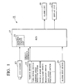
- Fig. 1 is a functional block diagram of a vehicle's circumference monitoring apparatus of the present invention.
- reference numeral 11 designates the vehicle's circumference monitoring apparatus of the invention.
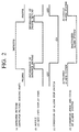
- Fig. 2 is a time chart for explanation of the operation of the vehicle's circumference monitoring apparatus 11.
- the vehicle's circumference monitoring apparatus 11 includes a CCD camera 13 operating as the imaging unit installed in the vehicle, a variety of sensors 15, an improper picture judging part 23 operating as the improper picture judging unit, an ECU 17 operating as the drive control unit, an alarm unit 19 and a display unit 21 both of which has a function as the informing unit, and an alarm stop switch 25.
- a switch will be referred to --SW-- for short, hereinafter.
- the vehicle is equipped with a plurality of CCD cameras in respective appropriate positions, for example, the vehicle's front section, the rear section, the side portions, the front/side part, the rear/side part, etc.
- these CCD cameras may be arranged in order to take pictures of various obstacles, for example, neighboring vehicles existing in the vicinity of the front section, the rear section, the side portions, the front/side part and the rear/side part of the driver's own vehicle.
- the vehicle may be equipped with only one CCD camera for purpose of imaging a picture of the obstacles existing in a designated direction from the vehicle.
- the shown apparatus 11 has a single CCD camera 13 for ease of explanation.
- the group of sensors 15 includes of a turn signal SW outputting the indicating direction of a turn-signal, a steering angle sensor for detecting the steering angle of the vehicle, a vehicle speed sensor for detecting the velocity of the vehicle, a small lamp SW for outputting the information of ON/OFF state in a not-shown small lamp, a headlight SW for outputting the information of ON/OFF state in a not-shown headlight, a gear position SW for outputting the information about the present position of a shift lever, etc.
- the ECU 17 has the following functions of:
- the alarm unit 19 has three functions as follows. That is, the first function is to raise the alarm signal on receipt of the alarm command outputted from the ECU 17. The second function is to inform the passenger (driver) of a fact that the monitoring accuracy is reduced, on receipt of a drive control command outputted from the ECU 17. The third function is to inform the passenger of a fact that the monitoring accuracy is recovered to the normal condition, on receipt of the drive control command also outputted from the ECU 17.
- the display unit 21 has a function to selectively display one of two informations: one is an information about a fact that the monitoring accuracy of the vehicle's circumference is reduced; another is an information about a fact that the monitoring accuracy of the vehicle's circumference is recovered to the normal condition.
- the alarm stop SW 25 when there is generated an information that the monitoring accuracy of the vehicle's circumference is reduced, the alarm stop SW 25 is manipulated by the passenger. That is, the alarm stop SW 25 is constituted to have a function to stop such an operation of the alarm unit 19 as informing the passenger of the large critical level.
- the ECU 17 does apply the designated image processing on a picture which has been taken by the CCD camera 13 and sequentially inputted to the ECU 17. Further in the ECU 17, it is executed to judge whether or not the so-processed picture is inappropriate for judging the critical level about the driver's own vehicle.
- CCD cameras 13 in order to take pictures exhibiting the vehicle's rear, left-side and right-side views. In this case, these pictures are subjected to the above designated image processing, so that it is carried out to judge whether the pictures are improper or not.
- the above-mentioned application of the designated image processing may be replaced with another form where the judgement is carried out while referring to "an imaging environment" around the vehicle.
- the imaging environment around the vehicle means an imaging situation containing the climatic changes, such as rainfall, snowfall, fog, etc.
- the ECU 17 As the result of the judgement of improper/proper pictures, if it is judged that the picture on image is proper, it is carried out in the ECU 17 to apply the designated image processing on the picture taken by the CCD camera 13.
- the designated image processing is represented by extracting the neighboring vehicle's lighting sections (e.g. small-lamp, headlight, etc.) and the profile of obstacles, as characterized points. While monitoring the relative positional relationship between the obstacle on recognition and the vehicle, the ECU 17 carries out the following operation.
- the ECU 17 judges the magnitude of critical level on a synthetic consideration of the relative positional relationship between the obstacle and the vehicle and the approaching speed therebetween. Thus, it is executed to judge whether there is produced a possibility of collision or involving the obstacle. Note, for comparison with the obtained magnitude of critical level, the ECU 17 has a predetermined threshold level stored in a not-shown memory.
- the ECU 17 commands the alarm unit 19 to raise the alarm signal, on the assumption of a large critical level.
- the alarm unit 19 raises the alarm signal representing the critical level being enormous. In this way, it is possible to inform the passenger on the vehicle of the enormous critical level timely. Together with the information, it can be expected to effect the great contribution on the vehicle's safety driving while preventing the occurrence of accident, such as collision, involving, or the like, in advance.
- the ECU 17 commands the alarm unit 19 and the display unit 21 to give the passenger the information about the monitoring accuracy being deteriorated. Then, on receipt of the command, the alarm unit 19 provides the passenger with a voice message, for example, "Monitoring Accuracy is Reduced. Push Alarm Stop SW.”, or any warning sound, for example, a buzzer, a chime, or the like. Also, the display unit 21 provides the passenger with a display message, such as "Monitoring Accuracy is Reduced.
- Push Alarm Stop SW.” or the lighting of a warning lamp.
- the alarm stop SW 25 is turned to its side of "alarm stop” by the passenger. Consequently, the ECU 17 commands the alarm unit 19 to stop the warning operation, as shown with (c), (d) of Fig. 2.
- the alarm unit 19 stops the warning operation based on the judgement of critical level (inactivation of alarm system).
- the ECU 17 commands the alarm unit 19 and the display unit 21 to give the passenger the information about the monitoring accuracy being recovered to the normal condition.
- the alarm unit 19 provides the passenger with a voice message, such as "Monitoring Accuracy is Recovered. Release Alarm Stop SW.”, or any sound, for example, a buzzer, a chime, or the like.
- the display unit 21 provides the passenger with a display message, such as "Monitoring Accuracy is Recovered.
- the stop and recovery of the alarm operation is controlled by the passenger through the alarm stop SW 25. While, the same SW 25 may be eliminated in the modification. Then, if it is judged that the proper picture is shifted to the improper one, the alarm operation would be automatically stopped. Conversely, if it is judged that the improper picture is recovered to the proper one, the alarm operation would be automatically recovered. Then, the voice message might be, for example, "Warning is stopped as accuracy is reduced” in case of stopping the alarm operation, "Warning is recovered as accuracy is normal” in case of recovering the alarm operation, and so on.
Landscapes
- Engineering & Computer Science (AREA)
- Mechanical Engineering (AREA)
- Multimedia (AREA)
- Signal Processing (AREA)
- Closed-Circuit Television Systems (AREA)
- Traffic Control Systems (AREA)
- Image Processing (AREA)
Applications Claiming Priority (2)
| Application Number | Priority Date | Filing Date | Title |
|---|---|---|---|
| JP4886799 | 1999-02-25 | ||
| JP11048867A JP2000247197A (ja) | 1999-02-25 | 1999-02-25 | 車両用周辺監視方法、及びこの方法を適用した車両用周辺監視装置 |
Publications (3)
| Publication Number | Publication Date |
|---|---|
| EP1032209A2 true EP1032209A2 (de) | 2000-08-30 |
| EP1032209A3 EP1032209A3 (de) | 2001-08-29 |
| EP1032209B1 EP1032209B1 (de) | 2009-01-28 |
Family
ID=12815248
Family Applications (1)
| Application Number | Title | Priority Date | Filing Date |
|---|---|---|---|
| EP20000103420 Expired - Lifetime EP1032209B1 (de) | 1999-02-25 | 2000-02-25 | Vorrichtung und Verfahren zur Überwachung der Umgebung eines Fahrzeuges |
Country Status (3)
| Country | Link |
|---|---|
| EP (1) | EP1032209B1 (de) |
| JP (1) | JP2000247197A (de) |
| DE (1) | DE60041467D1 (de) |
Cited By (3)
| Publication number | Priority date | Publication date | Assignee | Title |
|---|---|---|---|---|
| US6583730B2 (en) | 2000-07-28 | 2003-06-24 | Lang-Mekra North America, Llc | Surveillance apparatus for a vehicle |
| WO2004086766A1 (de) * | 2003-03-24 | 2004-10-07 | Daimlerchrysler Ag | Ein-/ausschaltzkonzept für ein automobiles nachtsichtsystem |
| FR2860466A1 (fr) * | 2003-10-02 | 2005-04-08 | Daimler Chrysler Ag | Dispositif pour ameliorer les conditions de vision dans un vehicule |
Families Citing this family (5)
| Publication number | Priority date | Publication date | Assignee | Title |
|---|---|---|---|---|
| US6642840B2 (en) | 2000-07-28 | 2003-11-04 | Lang-Mekra North Amicica, Llc | Rearview mirror assembly with monitor |
| DE10036875A1 (de) | 2000-07-28 | 2002-02-28 | Mekra Lang Gmbh & Co Kg | Rückspiegel, insbesondere für Nutzfahrzeuge mit Kamera und Monitor |
| JP5129909B2 (ja) * | 2001-07-23 | 2013-01-30 | トヨタ自動車株式会社 | 走行支援装置 |
| JP2012040445A (ja) * | 2011-12-02 | 2012-03-01 | Terumo Corp | 腹膜透析装置 |
| JP6238715B2 (ja) * | 2013-12-09 | 2017-11-29 | 株式会社トヨタマップマスター | 経路探索装置及びその方法、並びに経路を探索するためのコンピュータプログラム及びコンピュータプログラムを記録した記録媒体 |
Family Cites Families (3)
| Publication number | Priority date | Publication date | Assignee | Title |
|---|---|---|---|---|
| DE4332612C2 (de) * | 1992-09-25 | 1996-02-22 | Yazaki Corp | Außenansichts-Überwachungsverfahren für Kraftfahrzeuge |
| JP3452268B2 (ja) * | 1993-08-06 | 2003-09-29 | 矢崎総業株式会社 | 車両用後側方監視方法 |
| JPH10119672A (ja) * | 1996-10-16 | 1998-05-12 | Isuzu Motors Ltd | 車両外部監視装置 |
-
1999
- 1999-02-25 JP JP11048867A patent/JP2000247197A/ja active Pending
-
2000
- 2000-02-25 EP EP20000103420 patent/EP1032209B1/de not_active Expired - Lifetime
- 2000-02-25 DE DE60041467T patent/DE60041467D1/de not_active Expired - Lifetime
Cited By (3)
| Publication number | Priority date | Publication date | Assignee | Title |
|---|---|---|---|---|
| US6583730B2 (en) | 2000-07-28 | 2003-06-24 | Lang-Mekra North America, Llc | Surveillance apparatus for a vehicle |
| WO2004086766A1 (de) * | 2003-03-24 | 2004-10-07 | Daimlerchrysler Ag | Ein-/ausschaltzkonzept für ein automobiles nachtsichtsystem |
| FR2860466A1 (fr) * | 2003-10-02 | 2005-04-08 | Daimler Chrysler Ag | Dispositif pour ameliorer les conditions de vision dans un vehicule |
Also Published As
| Publication number | Publication date |
|---|---|
| JP2000247197A (ja) | 2000-09-12 |
| EP1032209B1 (de) | 2009-01-28 |
| DE60041467D1 (de) | 2009-03-19 |
| EP1032209A3 (de) | 2001-08-29 |
Similar Documents
| Publication | Publication Date | Title |
|---|---|---|
| JP4654208B2 (ja) | 車載用走行環境認識装置 | |
| US7378947B2 (en) | Device and method for the active monitoring of the safety perimeter of a motor vehicle | |
| EP3657467B1 (de) | Vorderes fahrzeugtotwinkeldetektions- und warnsystem | |
| US11180164B2 (en) | Vehicle control apparatus, vehicle, and control method | |
| US12358533B2 (en) | System for assisting with driving a vehicle | |
| KR20200115640A (ko) | 차선 변경시 차량과 인접한 차선에 위치한 2차 물체와 차량 간의 충돌 위험을 검출하기 위한 시스템 및 방법 | |
| JP4541609B2 (ja) | 停止線認識装置、及び、その停止線認識装置を用いた車両用運転支援装置 | |
| JP2005309797A (ja) | 歩行者警報装置 | |
| CN113415273B (zh) | 一种汽车智能穿行障碍的系统和方法 | |
| JP2021049892A (ja) | 自動運転システム | |
| US20210084227A1 (en) | Method and apparatus for the spatially resolved detection of an object outside a transportation vehicle with the aid of a sensor installed in a transportation vehicle | |
| US20120206275A1 (en) | Blind area warning for vehicles | |
| CN112740220B (zh) | 用于交通灯识别的系统和方法 | |
| US5689249A (en) | Off-lane alarm apparatus | |
| JP6932631B2 (ja) | 画像表示装置及び運転支援システム | |
| EP1032209B1 (de) | Vorrichtung und Verfahren zur Überwachung der Umgebung eines Fahrzeuges | |
| US20240144699A1 (en) | Vehicle | |
| JP3639008B2 (ja) | ワイパ制御装置 | |
| US20230256967A1 (en) | Apparatus for controlling vehicle, method for controlling vehicle and control program thereof | |
| JP5166975B2 (ja) | 車両周辺監視装置および車両周辺監視方法 | |
| JP2002109699A (ja) | 車両運転支援装置 | |
| US20250102667A1 (en) | Vehicular blind spot monitoring system with enhanced monitoring along curved road | |
| KR102419764B1 (ko) | 외부 음향 경고 기능을 갖는 비상 보조 시스템 | |
| JP7468159B2 (ja) | 運転支援装置 | |
| JP6973566B2 (ja) | 運転支援装置 |
Legal Events
| Date | Code | Title | Description |
|---|---|---|---|
| PUAI | Public reference made under article 153(3) epc to a published international application that has entered the european phase |
Free format text: ORIGINAL CODE: 0009012 |
|
| 17P | Request for examination filed |
Effective date: 20000225 |
|
| AK | Designated contracting states |
Kind code of ref document: A2 Designated state(s): AT BE CH CY DE DK ES FI FR GB GR IE IT LI LU MC NL PT SE |
|
| AX | Request for extension of the european patent |
Free format text: AL;LT;LV;MK;RO;SI |
|
| PUAL | Search report despatched |
Free format text: ORIGINAL CODE: 0009013 |
|
| AK | Designated contracting states |
Kind code of ref document: A3 Designated state(s): AT BE CH CY DE DK ES FI FR GB GR IE IT LI LU MC NL PT SE |
|
| AX | Request for extension of the european patent |
Free format text: AL;LT;LV;MK;RO;SI |
|
| RIC1 | Information provided on ipc code assigned before grant |
Free format text: 7H 04N 7/18 A, 7B 60R 1/00 B |
|
| AKX | Designation fees paid |
Free format text: DE FR IT |
|
| RAP1 | Party data changed (applicant data changed or rights of an application transferred) |
Owner name: YAZAKI CORPORATION |
|
| 17Q | First examination report despatched |
Effective date: 20080221 |
|
| GRAP | Despatch of communication of intention to grant a patent |
Free format text: ORIGINAL CODE: EPIDOSNIGR1 |
|
| GRAS | Grant fee paid |
Free format text: ORIGINAL CODE: EPIDOSNIGR3 |
|
| GRAA | (expected) grant |
Free format text: ORIGINAL CODE: 0009210 |
|
| AK | Designated contracting states |
Kind code of ref document: B1 Designated state(s): DE FR IT |
|
| REF | Corresponds to: |
Ref document number: 60041467 Country of ref document: DE Date of ref document: 20090319 Kind code of ref document: P |
|
| PLBE | No opposition filed within time limit |
Free format text: ORIGINAL CODE: 0009261 |
|
| STAA | Information on the status of an ep patent application or granted ep patent |
Free format text: STATUS: NO OPPOSITION FILED WITHIN TIME LIMIT |
|
| 26N | No opposition filed |
Effective date: 20091029 |
|
| PG25 | Lapsed in a contracting state [announced via postgrant information from national office to epo] |
Ref country code: IT Free format text: LAPSE BECAUSE OF NON-PAYMENT OF DUE FEES Effective date: 20090225 |
|
| PGRI | Patent reinstated in contracting state [announced from national office to epo] |
Ref country code: IT Effective date: 20110616 |
|
| REG | Reference to a national code |
Ref country code: FR Ref legal event code: PLFP Year of fee payment: 16 |
|
| PGFP | Annual fee paid to national office [announced via postgrant information from national office to epo] |
Ref country code: DE Payment date: 20150218 Year of fee payment: 16 Ref country code: IT Payment date: 20150209 Year of fee payment: 16 |
|
| PGFP | Annual fee paid to national office [announced via postgrant information from national office to epo] |
Ref country code: FR Payment date: 20150210 Year of fee payment: 16 |
|
| REG | Reference to a national code |
Ref country code: DE Ref legal event code: R119 Ref document number: 60041467 Country of ref document: DE |
|
| REG | Reference to a national code |
Ref country code: FR Ref legal event code: ST Effective date: 20161028 |
|
| PG25 | Lapsed in a contracting state [announced via postgrant information from national office to epo] |
Ref country code: IT Free format text: LAPSE BECAUSE OF NON-PAYMENT OF DUE FEES Effective date: 20160225 |
|
| PG25 | Lapsed in a contracting state [announced via postgrant information from national office to epo] |
Ref country code: DE Free format text: LAPSE BECAUSE OF NON-PAYMENT OF DUE FEES Effective date: 20160901 Ref country code: FR Free format text: LAPSE BECAUSE OF NON-PAYMENT OF DUE FEES Effective date: 20160229 |