EP1032243A2 - Dispositif d'écouteur stéréophonique - Google Patents
Dispositif d'écouteur stéréophonique Download PDFInfo
- Publication number
- EP1032243A2 EP1032243A2 EP00101714A EP00101714A EP1032243A2 EP 1032243 A2 EP1032243 A2 EP 1032243A2 EP 00101714 A EP00101714 A EP 00101714A EP 00101714 A EP00101714 A EP 00101714A EP 1032243 A2 EP1032243 A2 EP 1032243A2
- Authority
- EP
- European Patent Office
- Prior art keywords
- anchor
- ear canal
- earphone
- diaphragm
- housing
- Prior art date
- Legal status (The legal status is an assumption and is not a legal conclusion. Google has not performed a legal analysis and makes no representation as to the accuracy of the status listed.)
- Withdrawn
Links
Images





Classifications
-
- H—ELECTRICITY
- H04—ELECTRIC COMMUNICATION TECHNIQUE
- H04R—LOUDSPEAKERS, MICROPHONES, GRAMOPHONE PICK-UPS OR LIKE ACOUSTIC ELECTROMECHANICAL TRANSDUCERS; ELECTRIC HEARING AIDS; PUBLIC ADDRESS SYSTEMS
- H04R1/00—Details of transducers, loudspeakers or microphones
- H04R1/10—Earpieces; Attachments therefor ; Earphones; Monophonic headphones
-
- H—ELECTRICITY
- H04—ELECTRIC COMMUNICATION TECHNIQUE
- H04R—LOUDSPEAKERS, MICROPHONES, GRAMOPHONE PICK-UPS OR LIKE ACOUSTIC ELECTROMECHANICAL TRANSDUCERS; ELECTRIC HEARING AIDS; PUBLIC ADDRESS SYSTEMS
- H04R1/00—Details of transducers, loudspeakers or microphones
- H04R1/10—Earpieces; Attachments therefor ; Earphones; Monophonic headphones
- H04R1/1058—Manufacture or assembly
-
- H—ELECTRICITY
- H04—ELECTRIC COMMUNICATION TECHNIQUE
- H04R—LOUDSPEAKERS, MICROPHONES, GRAMOPHONE PICK-UPS OR LIKE ACOUSTIC ELECTROMECHANICAL TRANSDUCERS; ELECTRIC HEARING AIDS; PUBLIC ADDRESS SYSTEMS
- H04R1/00—Details of transducers, loudspeakers or microphones
- H04R1/10—Earpieces; Attachments therefor ; Earphones; Monophonic headphones
- H04R1/1016—Earpieces of the intra-aural type
Definitions
- the present invention is directed to a stereophonic earphone apparatus for insertion within an ear canal of a user thereof.
- the apparatus includes a housing which has a first and a second end.
- the housing defines an enclosure for the reception therein of an electroacoustic transducer.
- a diaphragm is disposed within the enclosure adjacent to the transducer with the diaphragm defining a peripheral flange which is connected to the housing such that the diaphragm operably cooperates with the transducer for emitting sound waves therefrom.
- a cover is secured to the second end of the housing such that the diaphragm is disposed between the cover and the transducer.
- the anchor is of a generally conical configuration with the anchor tapering inwardly from the first extremity towards the second extremity.
- the anchor also defines a longitudinal passageway having a first and a second termination with the first termination being disposed adjacent to the cover and the first extremity of the anchor.
- a tube extends from the cover and is disposed within the passageway.
- the tube has an inner and an outer surface the arrangement being such that the outer surface of the tube extends contiguously along the passageway so that the tube prevents obturation of the passageway while permitting transmission of the sound waves from the diaphragm into the ear canal.
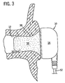
- Fig. 1 is a side elevational view, partially in section, of a stereophonic earphone apparatus generally designated 10 according to the present invention for insertion within an ear canal 12 of a user thereof as shown in Fig. 3.
- the apparatus 10 includes a housing generally designated 14 having a first and a second end 16 and 18 respectively.
- the housing 14 defines an enclosure 20 for the reception therein of an electroacoustic transducer 22.
- a diaphragm 24 is disposed within the enclosure 20 adjacent to the transducer 22.
- the diaphragm 24 defines a peripheral flange 26 which is connected to the housing 14. The arrangement is such that the diaphragm 24 operably cooperates with the transducer 22 for emitting sound waves therefrom.
- a cover 28 is secured to the second end 18 of the housing 14 such that the diaphragm 24 is disposed between the cover 28 and the transducer 22.
- a resilient anchor generally designated 30, has a first and a second extremity 32 and 34 respectively, with the first extremity 32 being removably secured to and extending from the cover 28.
- the anchor 30 is fabricated from a hydrophilic urethane foam 36 having a skinned over outer surface 38. The arrangement is such that when the anchor 30 is compressed as shown in Fig. 2, insertion of the anchor 30 within the ear canal 12 is permitted.
- the foam 36 has a shape restoration memory such that after insertion of the anchor 30 within the ear canal 12, the foam 36 gradually expands as shown in Fig. 3. As the foam 36 expands, the skinned over surface 38 comes into intimate contact with the ear canal 12 to secure the apparatus 10 comfortably within the ear canal 12.
- a tube 46 extends from the cover 28 with the tube 46 being disposed within the passageway 40.
- the tube 46 has an inner and an outer face 48 and 50 respectively so that the outer face 50 of the tube 46 extends contiguously along the passageway 40 so that the tube 46 prevents obturation of the passageway 40 while permitting transmission of sound waves from the diaphragm 24 into the ear canal 12.
- the housing 14 is fabricated from a plastics material.
- plastics material includes polyvinyl chloride (PVC) or any other suitable type of plastic.
- the electroacoustic transducer 22 includes an electrical conductor 52 for connecting the transducer 22 to a sound reproducing device represented generically by the box 54.
- the diaphragm 24, in a preferred embodiment of the present invention, is fabricated from MYLAR®.
- MYLAR® is a Registered Trademark of E. I. Du Pont De Nemours and Company.
- the cover 28 and the tube 46 are fabricated as a one piece molding for directing a transmission therethrough of the sound waves from the diaphragm 24 through the tube 46.
- the skinned over outer surface 38 permits thermal transfer from the ear canal 12 to the foam 36 for further enhancing conformity of the resilient anchor 30 to the ear canal 12 and for inhibiting transmission of extraneous ambient noise past the resilient anchor 30 into the ear canal 12.
- the second termination 44 of the passageway flares outwardly in a direction as indicated by the arrow 56 from the first termination 42 towards the second termination 44 for enhancing a high frequency response of the apparatus 10.
- the tube 46 extends from the first termination 42 of the passageway 40 towards the second termination 44 and more specifically the tube 46 terminates before the second termination 44 of the passageway 40.
- the length 58 and the diameter 60 of the tube 46 are balanced in order to optimize a natural acoustic response of the apparatus 10 and to provide an accurate frequency response thereof.
- the length of the anchor in a preferred embodiment to the present invention is 14 millimeters and the diameter thereof at the first end 32 is 13.7 millimeters.
- the passageway 40 has a diameter of 2.2 millimeters and the flared second end 34 flares outwardly to a diameter of 4.5 millimeters.
- the anchor tapers from the first end 32 to the second end 34 at an angle of 10 degrees.
- the tube 46 has a length of 11.7 millimeters and an internal diameter of 2.2 millimeters with the external diameter of the tube 46 being 3.2 millimeters.
- the foam 36 provides a seal against the ingress into the ear canal 12 of extraneous noise thus providing an extreme base frequency performance.
- the transducer 22 is electrically connected by a cord or electrical cable 52 to audio equipment.
- audio equipment includes a home audio equipment, a portable audio equipment, a computer sound board or any other type of professional sound equipment generically depicted by the box 54.
- an earphone 10 includes a housing 14 having a front face 15, a magnetic circuit or transducer 22 received in the housing 14, a diaphragm 24 magnetically coupled to the magnetic circuit 22, the diaphragm 24 having a diameter D substantially equal to a diameter D1 of the housing 14.
- Resilient member 30 is attached to front face 15 of housing 14 and is aligned with diaphragm 24, for compression insertion into aural meatus or ear canal 12 of a user. Once in the meatus 12, re-expansion occurs so as to provide a high fidelity sonic connection between diaphragm 24 and an eardrum of the user of earphone 10.
- Annular flange 27 extends from front face 15, and flange 27 projects generally normal to the diaphragm 24. Flange 27 fits over and is secured to resilient member 30.
- Resilient member 30 is preferably of frusto-conical configuration and is fabricated from a hydrophilic urethane foam 36. Member 30 has a skinned over outer surface 38 such that when foam 36 expands, the skinned over surface 38 comes into intimate contact with the aural meats 12 to secure the earphone 10 comfortably within the aural meats 12 as best shown in Fig. 3.
- earphone 10 in yet another aspect of the present invention, includes a housing 14, a magnetic circuit or transducer 22 received in the housing 14, a diaphragm 24 magnetically coupled to the magnetic circuit 22.
- the diaphragm 24 has a diameter D substantially equal to a diameter D1 of the housing 14.
- a protector plate cover 28 is attached to the housing 14 for covering the diaphragm 24.
- An annular support flange 27 extends from the protector plate cover 28 and projects generally normal to the cover 28.
- resilient member means 30 has a first and a second extremity 32 and 34 and is arranged to fit the first extremity 32 within the annular flange 27 so that the resilient means 30 connects to cover 28 and projects outwardly therefrom.
- the arrangement is such that when the resilient means 30 is compressed, insertion of the resilient means 30 into an aural meatus 12 of the user is permitted.
- the subsequent re-expansion of the resilient means 30 provides a high fidelity sonic connection between the diaphragm 24 and an eardrum of the user of the earphone 10.
- Fig. 6 is an exploded perspective view of the earphone 10 as shown in Fig. 1 to better illustrate the housing 14, the transducer 22, the cover 28 with the tube 46 extending therefrom, and the resilient member or anchor 30.
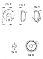
- Fig. 8 is a view taken on the line 8-8 of Fig. 7 and shows the housing 14 and an annular ridge 15 for securing the housing 14 to the cover 28.
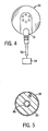
- Fig. 9 is a sectional view taken on the line 9-9 of Fig. 7 and shows an opening 17 for receiving a resilient strain relief 19 shown in Fig. 4 for relieving the cord 52.
- Fig. 14 is an end view of the cover 28 viewed from the left hand side of Fig. 1 with the anchor removed therefrom.
- Fig. 15 is a sectional view of the cover 28 taken on the line 15-15 of Fig. 14 showing the tube 46 extending from the cover 28.
- Fig. 15A is an enlarged view of a portion of the cover 28 circled in Fig. 15.
- Fig. 15A shows the lip 21 for securing the cover 28 to the housing 14.
- Fig. 17 is a sectional view of a further embodiment of the present invention which includes a tube 46A and a cover 28A which is secured to a housing 14A.
- the housing 14A defines an opening 17A for the reception therein of a resilient cord strain relief 19A so that the cord 52A is guided into the housing 14A.
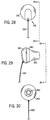
- Fig. 23 is a side elevational view of the earphone shown in Fig. 22 showing the cover 28B disposed between the anchor 30B and the housing 14B.
- Fig. 24 is a view taken on the line 24-24 of Fig. 23 and shows the anchor 30B surrounding the tube 46B.
- Fig. 27 is a perspective view of the earphone shown in Fig. 22 showing the opening 17B and the housing 14B.
- the present invention provides a unique stereophonic earphone apparatus which comfortably fits within the ear canal of a user and which provides an improved frequency response and enhanced base frequency performance.
- the individual components of the apparatus need not be formed in the disclosed shapes, or assembled in the disclosed configuration, but could be provided in virtually any shape, and assembled in virtually any configuration, so that the apparatus may be integrated with other equipment with which it is associated.
Landscapes
- Engineering & Computer Science (AREA)
- Physics & Mathematics (AREA)
- Acoustics & Sound (AREA)
- Signal Processing (AREA)
- Manufacturing & Machinery (AREA)
- Headphones And Earphones (AREA)
Applications Claiming Priority (2)
| Application Number | Priority Date | Filing Date | Title |
|---|---|---|---|
| US257664 | 1988-10-14 | ||
| US25766499A | 1999-02-25 | 1999-02-25 |
Publications (2)
| Publication Number | Publication Date |
|---|---|
| EP1032243A2 true EP1032243A2 (fr) | 2000-08-30 |
| EP1032243A3 EP1032243A3 (fr) | 2007-03-14 |
Family
ID=22977228
Family Applications (1)
| Application Number | Title | Priority Date | Filing Date |
|---|---|---|---|
| EP00101714A Withdrawn EP1032243A3 (fr) | 1999-02-25 | 2000-01-27 | Dispositif d'écouteur stéréophonique |
Country Status (7)
| Country | Link |
|---|---|
| EP (1) | EP1032243A3 (fr) |
| JP (1) | JP2000253478A (fr) |
| KR (1) | KR20000058143A (fr) |
| AU (1) | AU1637000A (fr) |
| BR (1) | BR0000773A (fr) |
| CA (1) | CA2297423A1 (fr) |
| TW (1) | TW478286B (fr) |
Cited By (15)
| Publication number | Priority date | Publication date | Assignee | Title |
|---|---|---|---|---|
| WO2007079948A1 (fr) * | 2005-12-29 | 2007-07-19 | Sennheiser Electronic Gmbh & Co.Kg | Casque d'écoute |
| GB2438910A (en) * | 2006-06-09 | 2007-12-12 | Cotron Corp | Earphone with a sound guiding tube |
| USD621388S1 (en) | 2009-03-20 | 2010-08-10 | Koss Corporation | Earphone |
| CN1992989B (zh) * | 2005-12-29 | 2011-08-03 | 三星电子株式会社 | 具有可变管道单元的耳机 |
| WO2013119913A1 (fr) * | 2012-02-08 | 2013-08-15 | Decibullz Llc | Système d'écouteur pouvant être moulé |
| CN103826188A (zh) * | 2014-02-21 | 2014-05-28 | 青岛歌尔声学科技有限公司 | 一种入耳式动铁耳机及安装有该耳机的头戴耳机 |
| US9179211B2 (en) | 2012-02-08 | 2015-11-03 | Decibullz Llc | Double seal moldable earpiece system |
| US10149038B2 (en) | 2017-01-20 | 2018-12-04 | Decibullz Llc | Earpiece intra-auricular support system |
| USD836614S1 (en) | 2013-02-07 | 2018-12-25 | Decibullz Llc | Moldable earpiece |
| US10321219B2 (en) | 2015-12-28 | 2019-06-11 | Hearing Components, Inc. | Earphone tip with universal sound port attachment core |
| US10507599B2 (en) | 2017-04-07 | 2019-12-17 | Decibullz Llc | Moldable earpiece heating case |
| US10728648B2 (en) | 2017-08-23 | 2020-07-28 | Decibullz Llc | Reconfigurable intra-auricular support |
| USD925493S1 (en) | 2019-11-25 | 2021-07-20 | Decibullz Llc | Intra-auricular earbud support |
| WO2022016511A1 (fr) * | 2020-07-24 | 2022-01-27 | 华为技术有限公司 | Procédé et appareil d'annulation active du bruit |
| US12593162B2 (en) * | 2023-04-18 | 2026-03-31 | William Struckman | Earbud housing apparatus and method of manufacturing |
Families Citing this family (3)
| Publication number | Priority date | Publication date | Assignee | Title |
|---|---|---|---|---|
| KR101100690B1 (ko) | 2008-04-30 | 2012-01-03 | 카부시키가이샤 하쯔메야 | 음향장치 |
| CN101370320B (zh) * | 2008-09-27 | 2012-05-30 | 刘国清 | 包括塑料构件、木质构件和金属构件的耳塞及其制作方法 |
| CN103269466B (zh) * | 2013-05-24 | 2017-02-08 | 青岛歌尔声学科技有限公司 | 配合耳朵形状的耳塞 |
Family Cites Families (6)
| Publication number | Priority date | Publication date | Assignee | Title |
|---|---|---|---|---|
| US2430229A (en) * | 1943-10-23 | 1947-11-04 | Zenith Radio Corp | Hearing aid earpiece |
| GB606272A (en) * | 1945-08-23 | 1948-08-11 | Zenith Radio Corp | Improvements in earphone assemblies |
| US5002151A (en) * | 1986-12-05 | 1991-03-26 | Minnesota Mining And Manufacturing Company | Ear piece having disposable, compressible polymeric foam sleeve |
| AU4920890A (en) * | 1989-02-13 | 1990-08-16 | Koss Corporation | Earphone having resilient insertion device |
| US5319163A (en) * | 1990-06-07 | 1994-06-07 | Scott Robert T | Waterproof earmold-to-earphone adapter |
| AR012683A1 (es) * | 1997-07-29 | 2000-11-08 | Decibel Instr Inc | Un acoplador acustico intracanal, el adaptador acustico intracanal que lo contiene y un dispositivo de distribucion de acopladores que lo contiene |
-
2000
- 2000-01-27 EP EP00101714A patent/EP1032243A3/fr not_active Withdrawn
- 2000-01-28 CA CA002297423A patent/CA2297423A1/fr not_active Abandoned
- 2000-02-11 AU AU16370/00A patent/AU1637000A/en not_active Abandoned
- 2000-02-18 JP JP2000041300A patent/JP2000253478A/ja active Pending
- 2000-02-22 KR KR1020000008544A patent/KR20000058143A/ko not_active Withdrawn
- 2000-02-23 BR BR0000773-0A patent/BR0000773A/pt not_active Application Discontinuation
- 2000-05-29 TW TW089103259A patent/TW478286B/zh not_active IP Right Cessation
Cited By (30)
| Publication number | Priority date | Publication date | Assignee | Title |
|---|---|---|---|---|
| WO2007079948A1 (fr) * | 2005-12-29 | 2007-07-19 | Sennheiser Electronic Gmbh & Co.Kg | Casque d'écoute |
| CN1992989B (zh) * | 2005-12-29 | 2011-08-03 | 三星电子株式会社 | 具有可变管道单元的耳机 |
| GB2438910A (en) * | 2006-06-09 | 2007-12-12 | Cotron Corp | Earphone with a sound guiding tube |
| US7697710B2 (en) | 2006-06-09 | 2010-04-13 | Cotron Corporation | Earphone with a sound guiding tube |
| GB2438910B (en) * | 2006-06-09 | 2011-06-22 | Cotron Corp | Earphone with a sound guiding tube |
| USD621388S1 (en) | 2009-03-20 | 2010-08-10 | Koss Corporation | Earphone |
| US9179211B2 (en) | 2012-02-08 | 2015-11-03 | Decibullz Llc | Double seal moldable earpiece system |
| WO2013119913A1 (fr) * | 2012-02-08 | 2013-08-15 | Decibullz Llc | Système d'écouteur pouvant être moulé |
| US9451353B2 (en) | 2012-02-08 | 2016-09-20 | Decibullz Llc | Moldable earpiece system |
| US9628889B2 (en) | 2012-02-08 | 2017-04-18 | Decibullz Llc | Moldable earpiece system |
| US9769555B2 (en) | 2012-02-08 | 2017-09-19 | Decibullz Llc | Moldable earpiece system |
| US10091571B2 (en) | 2012-02-08 | 2018-10-02 | Decibullz Llc | Moldable earpiece system |
| US11750961B2 (en) | 2012-02-08 | 2023-09-05 | Decibullz Llc | Moldable earpiece system |
| US11303986B2 (en) | 2012-02-08 | 2022-04-12 | Decibullz Llc | Moldable earpiece system |
| US10779073B2 (en) | 2012-02-08 | 2020-09-15 | Decibullz Llc | Moldable earpiece system |
| USD865721S1 (en) | 2013-02-07 | 2019-11-05 | Decibullz Llc | Moldable earpiece |
| USD836614S1 (en) | 2013-02-07 | 2018-12-25 | Decibullz Llc | Moldable earpiece |
| CN103826188A (zh) * | 2014-02-21 | 2014-05-28 | 青岛歌尔声学科技有限公司 | 一种入耳式动铁耳机及安装有该耳机的头戴耳机 |
| US10321219B2 (en) | 2015-12-28 | 2019-06-11 | Hearing Components, Inc. | Earphone tip with universal sound port attachment core |
| US10462552B2 (en) | 2017-01-20 | 2019-10-29 | Decibullz Llc | Earpiece intra-auricular support system |
| US10856065B2 (en) | 2017-01-20 | 2020-12-01 | Decibullz Llc | Earpiece intra-auricular support system |
| US11381902B2 (en) | 2017-01-20 | 2022-07-05 | Decibullz Llc | Earpiece intra-auricular support system |
| US11606639B2 (en) | 2017-01-20 | 2023-03-14 | Decibullz Llc | Earpiece intra-auricular support system |
| US10149038B2 (en) | 2017-01-20 | 2018-12-04 | Decibullz Llc | Earpiece intra-auricular support system |
| US10507599B2 (en) | 2017-04-07 | 2019-12-17 | Decibullz Llc | Moldable earpiece heating case |
| US10728648B2 (en) | 2017-08-23 | 2020-07-28 | Decibullz Llc | Reconfigurable intra-auricular support |
| US11490189B2 (en) | 2017-08-23 | 2022-11-01 | Decibullz Llc | Reconfigurable intra-auricular support |
| USD925493S1 (en) | 2019-11-25 | 2021-07-20 | Decibullz Llc | Intra-auricular earbud support |
| WO2022016511A1 (fr) * | 2020-07-24 | 2022-01-27 | 华为技术有限公司 | Procédé et appareil d'annulation active du bruit |
| US12593162B2 (en) * | 2023-04-18 | 2026-03-31 | William Struckman | Earbud housing apparatus and method of manufacturing |
Also Published As
| Publication number | Publication date |
|---|---|
| CA2297423A1 (fr) | 2000-08-25 |
| TW478286B (en) | 2002-03-01 |
| JP2000253478A (ja) | 2000-09-14 |
| EP1032243A3 (fr) | 2007-03-14 |
| BR0000773A (pt) | 2000-10-24 |
| AU1637000A (en) | 2000-08-31 |
| KR20000058143A (ko) | 2000-09-25 |
Similar Documents
| Publication | Publication Date | Title |
|---|---|---|
| EP1032243A2 (fr) | Dispositif d'écouteur stéréophonique | |
| US6212283B1 (en) | Articulation assembly for intracanal hearing devices | |
| US10200778B2 (en) | Earpiece with ergonomic extension | |
| US4972492A (en) | Earphone | |
| US7424123B2 (en) | Canal hearing device with tubular insert | |
| US6382346B2 (en) | Retention and extraction device for a hearing aid | |
| US6359993B2 (en) | Conformal tip for a hearing aid with integrated vent and retrieval cord | |
| US5979589A (en) | Flexible hearing aid | |
| US5917918A (en) | In-ear-canal audio receiver and stethoscope having the same | |
| JP7079274B2 (ja) | 補聴器用フレキシブル・イヤーピース | |
| US10791390B2 (en) | Flex-fit ear tip for headphones | |
| US7899200B2 (en) | Universal-fit hearing device | |
| US11381897B2 (en) | Variable eartip for earphone | |
| EP3334179B1 (fr) | Prothèse auditive avec un dôme étendu | |
| EP0383483A1 (fr) | Ecouteur à élément de support élastique | |
| US12003909B2 (en) | Modular earphone | |
| EP4164252A2 (fr) | Écouteur et dispositif d'aide auditive le comprenant | |
| EP2025202A1 (fr) | Dispositif auditif universel | |
| MXPA00001858A (en) | A stereophonic earphone apparatus | |
| KR20260036820A (ko) | 귀를 덮어 착용하는 노화성 난청 청력보청체 | |
| HK40045406A (en) | Modular earphone |
Legal Events
| Date | Code | Title | Description |
|---|---|---|---|
| PUAI | Public reference made under article 153(3) epc to a published international application that has entered the european phase |
Free format text: ORIGINAL CODE: 0009012 |
|
| AK | Designated contracting states |
Kind code of ref document: A2 Designated state(s): AT BE CH CY DE DK ES FI FR GB GR IE IT LI LU MC NL PT SE |
|
| AX | Request for extension of the european patent |
Free format text: AL;LT;LV;MK;RO;SI |
|
| PUAL | Search report despatched |
Free format text: ORIGINAL CODE: 0009013 |
|
| AK | Designated contracting states |
Kind code of ref document: A3 Designated state(s): AT BE CH CY DE DK ES FI FR GB GR IE IT LI LU MC NL PT SE |
|
| AX | Request for extension of the european patent |
Extension state: AL LT LV MK RO SI |
|
| 17P | Request for examination filed |
Effective date: 20070814 |
|
| 17Q | First examination report despatched |
Effective date: 20071008 |
|
| AKX | Designation fees paid |
Designated state(s): AT BE CH CY DE DK ES FI FR GB GR IE IT LI LU MC NL PT SE |
|
| STAA | Information on the status of an ep patent application or granted ep patent |
Free format text: STATUS: THE APPLICATION IS DEEMED TO BE WITHDRAWN |
|
| 18D | Application deemed to be withdrawn |
Effective date: 20080219 |