EP1032485B1 - Halbleiterscheiben-läppmaschine - Google Patents
Halbleiterscheiben-läppmaschine Download PDFInfo
- Publication number
- EP1032485B1 EP1032485B1 EP98954779A EP98954779A EP1032485B1 EP 1032485 B1 EP1032485 B1 EP 1032485B1 EP 98954779 A EP98954779 A EP 98954779A EP 98954779 A EP98954779 A EP 98954779A EP 1032485 B1 EP1032485 B1 EP 1032485B1
- Authority
- EP
- European Patent Office
- Prior art keywords
- cooling
- disc
- turn table
- polishing
- polisher
- Prior art date
- Legal status (The legal status is an assumption and is not a legal conclusion. Google has not performed a legal analysis and makes no representation as to the accuracy of the status listed.)
- Expired - Lifetime
Links
Images
Classifications
-
- B—PERFORMING OPERATIONS; TRANSPORTING
- B24—GRINDING; POLISHING
- B24B—MACHINES, DEVICES, OR PROCESSES FOR GRINDING OR POLISHING; DRESSING OR CONDITIONING OF ABRADING SURFACES; FEEDING OF GRINDING, POLISHING, OR LAPPING AGENTS
- B24B37/00—Lapping machines or devices; Accessories
- B24B37/04—Lapping machines or devices; Accessories designed for working plane surfaces
- B24B37/07—Lapping machines or devices; Accessories designed for working plane surfaces characterised by the movement of the work or lapping tool
- B24B37/10—Lapping machines or devices; Accessories designed for working plane surfaces characterised by the movement of the work or lapping tool for single side lapping
- B24B37/105—Lapping machines or devices; Accessories designed for working plane surfaces characterised by the movement of the work or lapping tool for single side lapping the workpieces or work carriers being actively moved by a drive, e.g. in a combined rotary and translatory movement
-
- H—ELECTRICITY
- H10—SEMICONDUCTOR DEVICES; ELECTRIC SOLID-STATE DEVICES NOT OTHERWISE PROVIDED FOR
- H10P—GENERIC PROCESSES OR APPARATUS FOR THE MANUFACTURE OR TREATMENT OF DEVICES COVERED BY CLASS H10
- H10P50/00—Etching of wafers, substrates or parts of devices
-
- B—PERFORMING OPERATIONS; TRANSPORTING
- B24—GRINDING; POLISHING
- B24B—MACHINES, DEVICES, OR PROCESSES FOR GRINDING OR POLISHING; DRESSING OR CONDITIONING OF ABRADING SURFACES; FEEDING OF GRINDING, POLISHING, OR LAPPING AGENTS
- B24B37/00—Lapping machines or devices; Accessories
- B24B37/11—Lapping tools
- B24B37/20—Lapping pads for working plane surfaces
-
- B—PERFORMING OPERATIONS; TRANSPORTING
- B24—GRINDING; POLISHING
- B24B—MACHINES, DEVICES, OR PROCESSES FOR GRINDING OR POLISHING; DRESSING OR CONDITIONING OF ABRADING SURFACES; FEEDING OF GRINDING, POLISHING, OR LAPPING AGENTS
- B24B49/00—Measuring or gauging equipment for controlling the feed movement of the grinding tool or work; Arrangements of indicating or measuring equipment, e.g. for indicating the start of the grinding operation
- B24B49/14—Measuring or gauging equipment for controlling the feed movement of the grinding tool or work; Arrangements of indicating or measuring equipment, e.g. for indicating the start of the grinding operation taking regard of the temperature during grinding
-
- B—PERFORMING OPERATIONS; TRANSPORTING
- B24—GRINDING; POLISHING
- B24B—MACHINES, DEVICES, OR PROCESSES FOR GRINDING OR POLISHING; DRESSING OR CONDITIONING OF ABRADING SURFACES; FEEDING OF GRINDING, POLISHING, OR LAPPING AGENTS
- B24B55/00—Safety devices for grinding or polishing machines; Accessories fitted to grinding or polishing machines for keeping tools or parts of the machine in good working condition
- B24B55/02—Equipment for cooling the grinding surfaces, e.g. devices for feeding coolant
-
- B—PERFORMING OPERATIONS; TRANSPORTING
- B24—GRINDING; POLISHING
- B24B—MACHINES, DEVICES, OR PROCESSES FOR GRINDING OR POLISHING; DRESSING OR CONDITIONING OF ABRADING SURFACES; FEEDING OF GRINDING, POLISHING, OR LAPPING AGENTS
- B24B57/00—Devices for feeding, applying, grading or recovering grinding, polishing or lapping agents
- B24B57/02—Devices for feeding, applying, grading or recovering grinding, polishing or lapping agents for feeding of fluid, sprayed, pulverised, or liquefied grinding, polishing or lapping agents
Definitions
- the present invention relates to a polisher, in particular, a polisher for polishing a semiconductor wafer, and more specifically to a system for cooling a turn table of such a polisher having a polishing surface for polishing a semiconductor wafer.
- a typical polisher of this type is for example described in EP-A-0 803 329.
- the polisher includes a turn table provided with a polishing pad on an upper surface thereof, a drive shaft fixedly connected to the center of a lower surface of the turn table for drivingly rotating the turn table about its axis, a wafer carrier for holding a semiconductor wafer in contact with an upper polishing surface of the polishing pad to polish the wafer, and a slurry nozzle for supplying slurry onto the polishing surface to effect a polishing operation mechanically and chemically by a combination of the polishing pad and the supplied slurry.
- a turn table of such a type of polisher it is desirable for a turn table of such a type of polisher to be positively cooled in order to deprive the polishing pad of heat generated in a polishing operation, although the polishing pad is cooled by the slurry to some extent. Consequently, it is conventional for such a polisher to be provided with a cooling system including a cooling fluid path extending inside of the turn table for flowing therethrough a cooling fluid received from an outside cooling fluid supply.
- a fluid coupler provided in the cooling system to receive a cooling fluid from an outside cooling supply is conventionally located in a drive shaft which is connected to a drive mechanism for driving the shaft, the construction of a combination of the drive shaft and those devices associated with the shaft is complicated thereby causing problems of cost, maintenance and so on.
- An object of the present invention is therefore to solve such problems as are involved in such a conventional polisher.
- a polisher comprises a turn table having first and second end surfaces which are substantially normal to an axis of the turn table.
- the first end surface defines a polishing surface for polishing an article.
- a drive shaft is connected to the turn table in such a manner that the shaft extends along the axis of the turn table outwardly from the second end surface of the turn table.
- the polisher further includes a cooling system which comprises a cooling fluid path provided in the turn table for passing a cooling fluid therethrough to deprive the polishing surface of heat generated in a polishing operation and a fluid coupler provided at the center of the first end surface of the turn table for fluidly connecting the cooling fluid path with a cooling fluid supply outside of the turn table.
- the turn table comprises a rotatable disc and a disc-like polishing member such as a synthetic resin polishing pad, a grindstone disc or the like axially aligned with the rotatable disc.
- the rotatable disc defines the above-noted second end surface of the turn table and the polishing member defines the polishing surface.
- the cooling system includes a cooling disc provided between the polishing member and the rotatable disc in which the above-stated cooling fluid path is formed.
- the cooling disc is removably connected to the rotatable disc.
- the cooling disc may be integrally formed with or integrally incorporated into the rotatable disc.
- the polishing member is provided with an opening at the center of the polishing member thereby exposing the center portion of the cooling disc, and the fluid coupler is mounted on the center portion of the cooling disc exposed by the opening.
- the fluid coupler may include a rotatable coupler body which is fixedly mounted on the center portion of the cooling disc and has a connection path fluidly connected to the cooling fluid path in the cooling disc and a stationary central member rotatably connected to the coupler body at the center of the coupler body thereby enabling the coupler body to rotate together with the cooling disc relative to the stationary central member.
- the stationary central member includes a fluid path having a first end port adapted to be fluidly connected to the cooling fluid supply and a second end port fluidly connected to the connecting path in the coupler body.
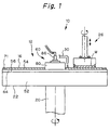
- a polisher 10 shown in Fig. 1 includes a turn table 12 having an upper polishing surface 16, a vertical drive shaft 20 connected to a lower surface 22 of the turn table at the center thereof for rotatably driving the turn table, a wafer carrier 26 for holding a semiconductor wafer W in contact with the polishing surface 16 and a nozzle 30 for supplying a slurry onto the polishing surface 16.
- the turn table 12 of the polisher 10 includes a rotatable disc 52 defining the above-stated lower surface 22 of the turn table, and a polishing member 54 such as a synthetic resin polishing pad, a grindstone disc or the like provided over an upper surface 56 of the rotatable disc 52 the upper surface of which constitutes the above-stated polishing surface 16.
- the turn table 12 and the wafer carrier 26 are rotated about their respective axes, while supplying a slurry through the nozzle 30, whereby the wafer is polished mechanically and chemically by a combination of the polishing surface 16 and the supplied slurry.
- the polisher 10 in accordance with the present invention further includes a cooling system 60 for cooling the polishing member 54 to deprive the polishing surface 16 of a heat generated by friction between the wafer W and the polishing surface 16 in a polishing operation as stated above.
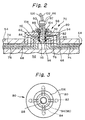
- the cooling system 60 includes a cooling disc 64 provided between the polishing member 54 and the rotatable disc 52 which cooling disc includes a cooling fluid path 68 provided therein and a fluid coupler 70 provided on the cooling disc 64 at the center thereof for fluidly connecting the cooling fluid path 68 in the cooling disc with a cooling fluid supply (not shown) outside of the turn table.
- the cooling disc 64 is removably fastened to the rotatable disc 52 by bolts 71 located along the periphery of the cooling disc and the polishing member 54 is adhered to the upper surface of the cooling disc.
- the cooling disc 64 may be integrally incorporated into or integrally formed with the rotatable disc 52.
- the cooling fluid path 68 is in the form of a round-trip path and includes a plurality sending paths 74 which extend in radial directions of the cooling disc 64 and are spaced from each other in a circumferential direction of the same and a plurality of return paths 76 which also extend radially and are connected to the sending paths 74 at around the periphery of the cooling disc. As shown, the sending paths 74 are positioned closer to the polishing member 54 than the return-paths taking a cooling efficiency into consideration.
- the fluid coupler 70 includes a rotatable coupler body 80 fixedly mounted on the center portion of the cooling disc 64 and having a sending connection path 82 and a return connection path 84 which are respectively connected to the sending paths 74 and the return paths 76 of the cooling disc.
- the coupler 70 further includes a stationary cylindrical central member 86 inserted into a vertical hole 88 formed at the center of the rotatable coupler body 80 in such a manner that the rotatable coupler body 80 can rotate about its axis together with the rotatable disc 52 relative to the stationary central member 86.
- the stationary central member has a sending path 90 and a return path 92 respectively adapted to fluidly connect the sending connection path 82 and the returnconnection path 84 in the coupler body 80 to the cooling fluid supply (not shown) through pipes 100, 102 connected thereto so as to form a circular path for supplying a cooling fluid from the supply to the cooling disc 64 through the sending path 90, the sending connection path 82 and the sending paths 74 and for returning the cooling fluid from the cooling disc to the cooling fluid supply through the return paths 76, the return connection path 84 and the return path 92 in order to cool the returned cooling fluid.
- the outlets of the sending path 90 and the return path 92 in the stationary central member are connected to the sending connection paths 82 and the return connection paths 84 through circular grooves 94, 96 formed in the inner wall of the vertical hole 88 of the rotational coupler body which are, respectively, fluidly connected to the sending connection paths 82 and the return connection paths 84 and are positioned at the same levels as those of the lower ends of the sending path 90 and the return path 92 of the stationary central member 80 facing the inner wall of the vertical hole, whereby the sending path 90 and the return path 92 of the stationary central member are always fluidly connected to the sending connection paths 82 and the return connection paths 84, respectively.
- a thrust bearing 98 is provided between the stationary central member 86 and the rotatable coupler body 80 which consists of a collar 104 integrally formed on the stationary central member 86 and an annular bearing member 106 fixedly connected to the top surface of the rotatable coupler body 80 to surround the collar so that the rotatable coupler body 80 can stably rotate about its axis relative to the stationary central member 86 .
- Reference numerals 110 designate O-rings for sealing the above-stated cooling fluid paths.
- a cooling system is provided on a polisher turn table having a polishing surface free of a drive shaft of the turn, whereby it is possible to make the construction of the cooling system simple thereby simplifying maintenance, lowering costs and so. Accordingly, this invention also makes it possible to enhance cooling of a polishing member.
Landscapes
- Engineering & Computer Science (AREA)
- Mechanical Engineering (AREA)
- Finish Polishing, Edge Sharpening, And Grinding By Specific Grinding Devices (AREA)
- Mechanical Treatment Of Semiconductor (AREA)
- Grinding-Machine Dressing And Accessory Apparatuses (AREA)
Claims (9)
- Eine Poliervorrichtung (10) die folgendes aufweist:einen Drehtisch (12) mit ersten und zweiten Endoberflächen (16, 22) die im wesentlichen senkrecht zu einer Achse des Drehtisches verlaufen, wobei die erste Endoberfläche (16) eine Polieroberfläche für das Polieren eines Gegenstandes definiert,eine Antriebswelle (20) verbunden mit dem Drehtisch (12) und sich entlang der Achse des Drehtisches (22) nach Außen von der erwähnten zweiten Endoberfläche (22) des Drehtisches (12) erstreckend, wobei die Antriebswelle (20) geeignet ist den Drehtisch (12) drehbar anzutreiben, undein Kühlsystem (60) mit einem Kühlströmungsmittelpfad (68) vorgesehen in dem Drehtisch (12) zum Durchleiten eines Kühlströmungsmittels dahindurch, um von der erwähnten Polieroberfläche in einem Poliervorgang erzeugte Wärme abzuführen, dadurch gekennzeichnet, das ein Strömungsmittelkoppler (70) an der Mitte der ersten Endoberfläche (16) des Drehtisches (12) vorgesehen ist, um den Kühlströmungsmittelpfad (68) mit einer Kühlströmungsmittelversorgung außerhalb des Drehtisches strömungsmittelmäßig zu verbinden.
- Poliervorrichtung (10) nach Anspruch 1, wobei der Drehtisch (12) eine drehbare Scheibe (52) und ein scheibenartiges Polierglied (54) aufweist, und zwar axial ausgerichtet mit der drehbaren Scheibe (52), und wobei die drehbare Scheibe (52) die erwähnte zweite Endoberfläche (22) des Drehtisches definiert, und wobei das Polierglied (54) die erwähnte Polieroberfläche definiert, und das Kühlsystem (60) eine Kühlscheibe (64) aufweist, und zwar vorgesehen zwischen dem erwähnten Polierglied (54) und der erwähnten Drehscheibe (52), wobei die Kühlscheibe (64) mit dem erwähnten Kühlströmungsmittelpfad (68) darinnen vorgesehen ist.
- Poliervorrichtung (10) nach Anspruch 2, wobei die erwähnte Kühlscheibe (64) entfernbar auf der erwähnten Drehscheibe (52) vorgesehen ist.
- Eine Poliervorrichtung (10) nach Anspruch 2, wobei das erwähnte Polierglied (54) ein Polierkissen bzw. Polierpad ist.
- Eine Poliervorrichtung (10) nach Anspruch 2, wobei die Kühlscheibe (64) entfernbar auf dem Drehtisch (52) vorgesehen ist, und wobei das Polierglied (54) ein Polierkissen anhaftend an bzw. angeklebt an der Kühlscheibe (64) ist.
- Eine Poliervorrichtung (10) nach Anspruch 2, wobei das Polierglied (54) eine Schleifsteinscheibe ist.
- Eine Poliervorrichtung (10) nach Anspruch 2, wobei das Polierglied (54) an der Mitte des Polierglieds (54) mit einer Öffnung versehen ist, wodurch der Mittelteil der Kühlscheibe (64) freigelegt wird, und wobei der Strömungsmittelkoppler (70) an dem erwähnten Mittelteil der Kühlscheibe (64) freigelegt durch die erwähnte Öffnung angebracht ist.
- Eine Poliervorrichtung (10) nach Anspruch 7, wobei der Strömungsmittelkoppler (70) einen drehbaren Kupplerkörper (80) aufweist, und zwar koaxial und fest an dem Mittelteil der Kühlscheibe (64) angebracht und mit einem Kühlpfad (82, 84) strömungsmittelmäßig verbunden mit dem Kühlströmungsmittelpfad (68) in der Kühlscheibe (64) und mit einem stationären mittigen Glied (86) drehbar verbunden mit dem Kupplerkörper (80) an der Mitte des erwähnten Kupplerkörpers (80) wodurch der Kupplerkörper (80) in die Lage versetzt wird, zusammen mit der Kühlscheibe (64) relativ zu dem erwähnten stationären Mittelglied (86) zu rotieren, wobei das stationäre Mittelglied (86) mit einem Strömungsmittelpfad (80, 82) versehen ist, und zwar mit einem ersten Endteil geeignet für eine strömungsmittelmäßige Verbindung mit der Kühlströmungsmittelversorgung und einem zweiten Endanschluß strömungsmittelmäßig verbunden mit dem erwähnten Verbindungspfad des Kupplerkörpers (80).
- Eine Poliervorrichtung (10) nach Anspruch 8, wobei der drehbare Kupplerkörper (8) ein Durchgangsloch (88) an der Mitte desselben aufweist, und wobei das stationäre Mittelglied (86) koaxial und drehbar in dem Durchgangsloch (88) des Kupplerkörpers (80) aufgenommen ist.
Applications Claiming Priority (3)
| Application Number | Priority Date | Filing Date | Title |
|---|---|---|---|
| JP33803397A JPH11156715A (ja) | 1997-11-21 | 1997-11-21 | ポリッシング装置 |
| JP33803397 | 1997-11-21 | ||
| PCT/JP1998/005244 WO1999026760A1 (en) | 1997-11-21 | 1998-11-20 | Wafer polishing machine |
Publications (2)
| Publication Number | Publication Date |
|---|---|
| EP1032485A1 EP1032485A1 (de) | 2000-09-06 |
| EP1032485B1 true EP1032485B1 (de) | 2003-08-27 |
Family
ID=18314308
Family Applications (1)
| Application Number | Title | Priority Date | Filing Date |
|---|---|---|---|
| EP98954779A Expired - Lifetime EP1032485B1 (de) | 1997-11-21 | 1998-11-20 | Halbleiterscheiben-läppmaschine |
Country Status (6)
| Country | Link |
|---|---|
| US (1) | US6186872B1 (de) |
| EP (1) | EP1032485B1 (de) |
| JP (1) | JPH11156715A (de) |
| KR (1) | KR100555933B1 (de) |
| DE (1) | DE69817601T2 (de) |
| WO (1) | WO1999026760A1 (de) |
Families Citing this family (4)
| Publication number | Priority date | Publication date | Assignee | Title |
|---|---|---|---|---|
| US6579407B1 (en) * | 2000-06-30 | 2003-06-17 | Lam Research Corporation | Method and apparatus for aligning and setting the axis of rotation of spindles of a multi-body system |
| KR100681683B1 (ko) * | 2001-03-16 | 2007-02-09 | 동부일렉트로닉스 주식회사 | 가공물의 표면 연마장치 |
| WO2011106801A2 (en) * | 2010-06-14 | 2011-09-01 | Saint-Gobain Abrasives, Inc. | Apparatuses methods for coolant delivery |
| CN117961778B (zh) * | 2024-03-19 | 2025-03-18 | 上海致领半导体科技发展有限公司 | 一种用于重型碳化硅晶片加工的冷却系统、抛光设备及抛光系统 |
Family Cites Families (10)
| Publication number | Priority date | Publication date | Assignee | Title |
|---|---|---|---|---|
| DE3128880C2 (de) * | 1981-07-22 | 1987-03-19 | Fa. Peter Wolters, 2370 Rendsburg | Maschine zum Läppen oder Polieren |
| US4450652A (en) | 1981-09-04 | 1984-05-29 | Monsanto Company | Temperature control for wafer polishing |
| US5036625A (en) * | 1988-12-07 | 1991-08-06 | Anatoly Gosis | Lapping plate for a lapping and polishing machine |
| AU637087B2 (en) * | 1989-03-24 | 1993-05-20 | Sumitomo Electric Industries, Ltd. | Apparatus for grinding semiconductor wafer |
| JP3201833B2 (ja) | 1992-07-27 | 2001-08-27 | 東芝機械株式会社 | ポリッシング用加工定盤 |
| US5607718A (en) * | 1993-03-26 | 1997-03-04 | Kabushiki Kaisha Toshiba | Polishing method and polishing apparatus |
| JP3415886B2 (ja) | 1993-07-13 | 2003-06-09 | 富士通テン株式会社 | 内燃機関の点火制御装置 |
| JP3678468B2 (ja) * | 1995-07-18 | 2005-08-03 | 株式会社荏原製作所 | ポリッシング装置 |
| JP3734878B2 (ja) * | 1996-04-25 | 2006-01-11 | 不二越機械工業株式会社 | ウェーハの研磨装置 |
| US5873769A (en) * | 1997-05-30 | 1999-02-23 | Industrial Technology Research Institute | Temperature compensated chemical mechanical polishing to achieve uniform removal rates |
-
1997
- 1997-11-21 JP JP33803397A patent/JPH11156715A/ja active Pending
-
1998
- 1998-11-20 WO PCT/JP1998/005244 patent/WO1999026760A1/en not_active Ceased
- 1998-11-20 KR KR1020007001474A patent/KR100555933B1/ko not_active Expired - Fee Related
- 1998-11-20 US US09/485,299 patent/US6186872B1/en not_active Expired - Fee Related
- 1998-11-20 EP EP98954779A patent/EP1032485B1/de not_active Expired - Lifetime
- 1998-11-20 DE DE69817601T patent/DE69817601T2/de not_active Expired - Fee Related
Also Published As
| Publication number | Publication date |
|---|---|
| JPH11156715A (ja) | 1999-06-15 |
| KR100555933B1 (ko) | 2006-03-03 |
| EP1032485A1 (de) | 2000-09-06 |
| US6186872B1 (en) | 2001-02-13 |
| KR20010015569A (ko) | 2001-02-26 |
| WO1999026760A1 (en) | 1999-06-03 |
| DE69817601D1 (de) | 2003-10-02 |
| DE69817601T2 (de) | 2004-06-24 |
Similar Documents
| Publication | Publication Date | Title |
|---|---|---|
| US20080194189A1 (en) | Multiple Fluid Supplying Apparatus For Carrier of Semiconductor Wafer Polishing System | |
| KR100700807B1 (ko) | 반도체 웨이퍼의 화학적 기계적 연마 중에 연마액을 분사하는 시스템 | |
| US20150024662A1 (en) | Flexible diaphragm post-type floating and rigid abrading workholder | |
| CN102166731B (zh) | 磨削装置 | |
| US20180021911A1 (en) | Grinding apparatus | |
| CN113910072B (zh) | 吸盘转台和晶圆加工系统 | |
| JPH02256995A (ja) | 異る流体用回転接手 | |
| KR20030014645A (ko) | 동압 밀봉 장치 및 그를 이용한 회전 조인트 장치 | |
| EP1032485B1 (de) | Halbleiterscheiben-läppmaschine | |
| JP2975923B1 (ja) | 回転継手装置 | |
| US5791978A (en) | Bearing assembly for wafer planarization carrier | |
| JP4189181B2 (ja) | ロータリージョイント | |
| US20030194948A1 (en) | Chemical-mechanical polishing machine for polishing a wafer of material, and an abrasive delivery device fitted to such a machine | |
| KR100338404B1 (ko) | 컵휠형지석 및 그것을 구비한 평면연삭장치 | |
| KR20030034309A (ko) | 기판 파지 장치 | |
| JP3795198B2 (ja) | 基板保持装置及び該基板保持装置を備えたポリッシング装置 | |
| WO2007001100A9 (en) | Multiple fluid supplying apparatus for carrier of semiconductor wafer polishing system | |
| JP4163468B2 (ja) | 組立ロータリージョイント | |
| JPH0518035Y2 (de) | ||
| JP3126685B2 (ja) | スラリ流体用ロータリジョイント | |
| CN117198971B (zh) | 一种晶圆卡盘台 | |
| US20240420978A1 (en) | Retaining ring for chemical-mechanical polishing | |
| JP3795317B2 (ja) | 基板把持装置及び研磨装置 | |
| JP7256605B2 (ja) | 研削ホルダ、研削工具及び研削装置 | |
| JP2025143074A (ja) | Cmp装置及びcmp装置を用いた研磨済ワークの製造方法 |
Legal Events
| Date | Code | Title | Description |
|---|---|---|---|
| PUAI | Public reference made under article 153(3) epc to a published international application that has entered the european phase |
Free format text: ORIGINAL CODE: 0009012 |
|
| 17P | Request for examination filed |
Effective date: 20000208 |
|
| AK | Designated contracting states |
Kind code of ref document: A1 Designated state(s): DE FR |
|
| 17Q | First examination report despatched |
Effective date: 20020114 |
|
| GRAH | Despatch of communication of intention to grant a patent |
Free format text: ORIGINAL CODE: EPIDOS IGRA |
|
| GRAH | Despatch of communication of intention to grant a patent |
Free format text: ORIGINAL CODE: EPIDOS IGRA |
|
| GRAA | (expected) grant |
Free format text: ORIGINAL CODE: 0009210 |
|
| AK | Designated contracting states |
Designated state(s): DE FR |
|
| REF | Corresponds to: |
Ref document number: 69817601 Country of ref document: DE Date of ref document: 20031002 Kind code of ref document: P |
|
| ET | Fr: translation filed | ||
| PLBE | No opposition filed within time limit |
Free format text: ORIGINAL CODE: 0009261 |
|
| STAA | Information on the status of an ep patent application or granted ep patent |
Free format text: STATUS: NO OPPOSITION FILED WITHIN TIME LIMIT |
|
| 26N | No opposition filed |
Effective date: 20040528 |
|
| PGFP | Annual fee paid to national office [announced via postgrant information from national office to epo] |
Ref country code: FR Payment date: 20061108 Year of fee payment: 9 |
|
| PGFP | Annual fee paid to national office [announced via postgrant information from national office to epo] |
Ref country code: DE Payment date: 20061116 Year of fee payment: 9 |
|
| PG25 | Lapsed in a contracting state [announced via postgrant information from national office to epo] |
Ref country code: DE Free format text: LAPSE BECAUSE OF NON-PAYMENT OF DUE FEES Effective date: 20080603 |
|
| REG | Reference to a national code |
Ref country code: FR Ref legal event code: ST Effective date: 20080930 |
|
| PG25 | Lapsed in a contracting state [announced via postgrant information from national office to epo] |
Ref country code: FR Free format text: LAPSE BECAUSE OF NON-PAYMENT OF DUE FEES Effective date: 20071130 |