EP1032966B1 - Machine dynamoelectrique tournant par induction electromagnetique selon le principe des moteurs electriques lineaires - Google Patents
Machine dynamoelectrique tournant par induction electromagnetique selon le principe des moteurs electriques lineaires Download PDFInfo
- Publication number
- EP1032966B1 EP1032966B1 EP98929623A EP98929623A EP1032966B1 EP 1032966 B1 EP1032966 B1 EP 1032966B1 EP 98929623 A EP98929623 A EP 98929623A EP 98929623 A EP98929623 A EP 98929623A EP 1032966 B1 EP1032966 B1 EP 1032966B1
- Authority
- EP
- European Patent Office
- Prior art keywords
- rotor
- machine according
- stator
- electromagnetic machine
- electromagnetic
- Prior art date
- Legal status (The legal status is an assumption and is not a legal conclusion. Google has not performed a legal analysis and makes no representation as to the accuracy of the status listed.)
- Expired - Lifetime
Links
- 230000005674 electromagnetic induction Effects 0.000 title claims abstract description 5
- 239000000463 material Substances 0.000 claims description 6
- XEEYBQQBJWHFJM-UHFFFAOYSA-N Iron Chemical compound [Fe] XEEYBQQBJWHFJM-UHFFFAOYSA-N 0.000 claims description 4
- 230000004907 flux Effects 0.000 claims description 3
- 229910000838 Al alloy Inorganic materials 0.000 claims description 2
- 229910052742 iron Inorganic materials 0.000 claims description 2
- 230000008901 benefit Effects 0.000 description 6
- 230000005540 biological transmission Effects 0.000 description 6
- 230000006698 induction Effects 0.000 description 3
- 230000009467 reduction Effects 0.000 description 3
- 238000010276 construction Methods 0.000 description 2
- 230000010354 integration Effects 0.000 description 2
- 230000003993 interaction Effects 0.000 description 2
- 238000012423 maintenance Methods 0.000 description 2
- 230000009347 mechanical transmission Effects 0.000 description 2
- 210000000056 organ Anatomy 0.000 description 2
- 238000005406 washing Methods 0.000 description 2
- 239000004020 conductor Substances 0.000 description 1
- 238000001816 cooling Methods 0.000 description 1
- 238000005516 engineering process Methods 0.000 description 1
- 230000009349 indirect transmission Effects 0.000 description 1
- 230000004048 modification Effects 0.000 description 1
- 238000012986 modification Methods 0.000 description 1
- 210000003205 muscle Anatomy 0.000 description 1
- 238000004804 winding Methods 0.000 description 1
Images



Classifications
-
- H—ELECTRICITY
- H02—GENERATION; CONVERSION OR DISTRIBUTION OF ELECTRIC POWER
- H02K—DYNAMO-ELECTRIC MACHINES
- H02K41/00—Propulsion systems in which a rigid body is moved along a path due to dynamo-electric interaction between the body and a magnetic field travelling along the path
- H02K41/02—Linear motors; Sectional motors
- H02K41/03—Synchronous motors; Motors moving step by step; Reluctance motors
- H02K41/031—Synchronous motors; Motors moving step by step; Reluctance motors of the permanent magnet type
-
- B—PERFORMING OPERATIONS; TRANSPORTING
- B62—LAND VEHICLES FOR TRAVELLING OTHERWISE THAN ON RAILS
- B62M—RIDER PROPULSION OF WHEELED VEHICLES OR SLEDGES; POWERED PROPULSION OF SLEDGES OR SINGLE-TRACK CYCLES; TRANSMISSIONS SPECIALLY ADAPTED FOR SUCH VEHICLES
- B62M6/00—Rider propulsion of wheeled vehicles with additional source of power, e.g. combustion engine or electric motor
- B62M6/40—Rider propelled cycles with auxiliary electric motor
- B62M6/60—Rider propelled cycles with auxiliary electric motor power-driven at axle parts
- B62M6/65—Rider propelled cycles with auxiliary electric motor power-driven at axle parts with axle and driving shaft arranged coaxially
-
- B—PERFORMING OPERATIONS; TRANSPORTING
- B62—LAND VEHICLES FOR TRAVELLING OTHERWISE THAN ON RAILS
- B62M—RIDER PROPULSION OF WHEELED VEHICLES OR SLEDGES; POWERED PROPULSION OF SLEDGES OR SINGLE-TRACK CYCLES; TRANSMISSIONS SPECIALLY ADAPTED FOR SUCH VEHICLES
- B62M6/00—Rider propulsion of wheeled vehicles with additional source of power, e.g. combustion engine or electric motor
- B62M6/80—Accessories, e.g. power sources; Arrangements thereof
- B62M6/90—Batteries
-
- H—ELECTRICITY
- H02—GENERATION; CONVERSION OR DISTRIBUTION OF ELECTRIC POWER
- H02K—DYNAMO-ELECTRIC MACHINES
- H02K41/00—Propulsion systems in which a rigid body is moved along a path due to dynamo-electric interaction between the body and a magnetic field travelling along the path
- H02K41/02—Linear motors; Sectional motors
- H02K41/025—Asynchronous motors
-
- H—ELECTRICITY
- H02—GENERATION; CONVERSION OR DISTRIBUTION OF ELECTRIC POWER
- H02K—DYNAMO-ELECTRIC MACHINES
- H02K7/00—Arrangements for handling mechanical energy structurally associated with dynamo-electric machines, e.g. structural association with mechanical driving motors or auxiliary dynamo-electric machines
- H02K7/14—Structural association with mechanical loads, e.g. with hand-held machine tools or fans
-
- B—PERFORMING OPERATIONS; TRANSPORTING
- B62—LAND VEHICLES FOR TRAVELLING OTHERWISE THAN ON RAILS
- B62J—CYCLE SADDLES OR SEATS; AUXILIARY DEVICES OR ACCESSORIES SPECIALLY ADAPTED TO CYCLES AND NOT OTHERWISE PROVIDED FOR, e.g. ARTICLE CARRIERS OR CYCLE PROTECTORS
- B62J6/00—Arrangement of optical signalling or lighting devices on cycles; Mounting or supporting thereof; Circuits therefor
- B62J6/06—Arrangement of lighting dynamos or drives therefor
Definitions
- the present invention relates to a dynamo-electric machine rotating by electromagnetic induction such as it acts in linear electric motors.
- the linear electric motor can be thought of as being derived from. a normal asynchronous motor by longitudinally sectioning and rectifying both the stator and the rotor.
- the operating principle is based on the generation of a magnetic field which varies spatially with uniform rectilinear motion instead of with rotatory motion as occurs in the normal asynchronous motor.
- the inductor In the asynchronous linear motor, the inductor generates currents on the armature and the interaction between such currents and the inducting field gives rise to an inducting fores directed longitudinally.
- the present invention aims to overcome also the constraint of the extended shape which is the basis for the linear motor.
- linear motor principle is disclosed in the patent DE 2217466A.
- the patent discloses an induction motor comprising a disc of electrical conductor and a 3-element stator, each element comprising a core and windings.
- Another example of the linear motor principle can be found in GB1282485 A that discloses a ring-shaped rotor carried by fan blades, which extend radially outward from a hub mounted on a central shaft In any of these documents , the rotor is mounted on a central shaft.
- An example of a motor having a rotor in the form of a hoop can be found in the document GB2103768A. In this document the stator and the hoop are of semi-cylindrical section and are thus semi-toroidal in shape.
- the main object of the present invention is to realise a dynamo-electric machine, i.e. one operating both as a motor and as a generator, which employs the technology of the linear electric motor to allow realisations not effected so far on a rotating machine.
- the invention solves the problem of providing a dynamo-electric machine rotating by electromagnetic induction such as it acts in linear electric motors, which from a general standpoint is characterised in that it possesses a ring-shaped rotor in the form of a flattened annulus, being fitted with at least one circumferential rail engaged with sliding guides, and an inductance coil stator interacting at least with one part of said rotor.
- the present invention allows to realise a linear electric machine which, functioning for instance as a motor, has a linear armature closed in a loop at its ends to serve as a rotor, and a related stator, at least one fixed inductor, interacting with said armature at least on a part of its said loop.
- One of the advantages obtained through the present invention essentially consists of the fact that, when said rotor is mounted for rotation on sliding guides, the structure of the machine is essentially hollow, and inside it may be housed various contrivances for the direct integration of the machine itself with systems for the utilisation of mechanical or electrical energy, or both, depending on whether the dynamo-electric machine functions as a motor or as a generator, or as both at subsequent times.
- Another advantage is represented by the fact that the rotor of this machine can have a moment of inertia which can be easily modified by varying its radius. Hence it is possible to modify the torque produced for equal amounts of power supplied to the induction coil, in case of operation as a motor, with the consequent optimisation in the various applications.
- the need for gears or other reduction and indirect transmission means normally required to adapt the torque produced by the motors to the user is eliminated. In the absence of such reduction and transmission organs, the cost normally required for the utilisation of the mechanical energy is reduced, thanks to a lower number of necessary components, and the final mechanical efficiency is also increased.
- the power of the machine can be modifted consequently.
- the invention can have various types of power supply and efficiency, depending on whether it functions as a motor or as a generator.
- Yet another advantage of the invention is to allow large efficiencies simply by increasing the scale factor of the embodiments.
- the machine according to the invention is easily and conveniently integrated in all its applications, in particular in those having internal spaces with particular volumes and shapes.
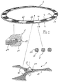
- the number 1 indicates a rotor
- the number 2 a stator
- the number 3 sliding guides for the rotation of the rotor 1
- the number 4 indicates a central support for the same rotor 1.
- the rotor I is obtained by closing in a loop the armature of a linear motor.
- the rotor 1 therefore is ring-shaped, like an annulus, and it has preferably flattened shape.
- the rotor comprises permanent magnets, generically indicated as 10 and 11, arranged in succession with their N, S polarities opposing one another in orderly fashion.
- Other embodiments of the rotor are shown and described hereafter with reference to Figures 2 and 3.
- the sliding guides 3 can be formed essentially by rollers 30 fastened and revolving adjacent to the rotor (as shown in subsequent figures), each roller 30 being provided with a circumferential groove 31.
- One or the other of the projections 13 and 14 serves as a guiding rail for the rotation of the rotor 1. Therefore, with this embodiment the machine according to the invention is internally hollow, allowing for multifarious applications, whereof some are shown and described below.
- the rotor 1 is splined onto a shaft 12 of the machine by means of the central support 4, comprising a hub 40 and multiple spokes, indicated generically as 41.
- the spokes 41 together may constitute a single disk (not shown).
- Figure 1 shows three spokes 41.
- the stator 2 is an inductor interacting at least with one part of the rotor 1. It comprises an inductance coil 20 and an electromagnetic core 21.
- the electromagnetic 21 presents an air gap 22.
- the stator 2 is fastened in such a way that the rotor I crosses through the air gap 22, so that the end facets of the electromagnetic core 21 face the permanent magnets 10, 11 of the rotor 1.
- the stator can comprise, as shown hereafter, at least an inductance coil and a closed magnetic core with flux concatenated with the rotor.
- a ring-shaped rotor 5 comprises, instead of the orderly succession of permanent magnets, a succession or self-induction turns generically indicated as 50.
- the stator is represented by three inductance coils crossed by respective current phases.
- a ring-shaped rotor 6 comprises a crown 60 made of material able to be magnetised, for instance soft iron, sandwiched between two opposite crowns 61, 62 made of a material not subject to magnetisation, such as an aluminium alloy.
- the stator is schematically shown as an inductor with three opposed poles 25, 25 powered in pairs with a respective phase of the power supply line A, B and C. The interaction between the fields of the poles integral with the stator inductor and the currents induced in the metallic rotor 6 produces, peripherally thereto, an accelerating force represented by the tangential arrow F in Figure 3.
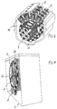
- FIG. 4 schematically shows an application of a machine with a central rotor support, functioning as a motor in a washing machine 7.
- This application of the machine highlights the advantages described above, among them the absence of some transmission organs, such as bearings, pulleys, transmission belt, the increase in efficiency, the reduction of the size of the appliance, the easier maintenance.
- the control unit of the motor according to the invention instead is similar to that of the traditional motor and therefore is not described.
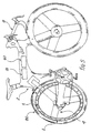
- FIG. 5 schematically shows another application of the machine with a central rotor support, to the driving wheel 80 of a bicycle 8.
- the rotor 1 is integral with the wheel 80, whilst the central support 4 of the rotor replaces the spokes of the wheel.
- the stator 2 is connected to a buffer battery 81, which is charged when the machine according to the invention functions as a generator, i.e. when muscle power is used, in downhill stretches of roads and when braking.
- the motor starts operating when high speeds are desired, or uphill or when, on a flat stretch of road, the rider wishes to proceed without effort.
- the control unit is shown schematically as 82. Immediately apparent are the advantages with respect to the other current systems of electric drive for bicycles, and like them the invention can use a solar cell battery charger.
- FIG. 6 schematically shows yet another application of the machine with a central rotor support as a driving device for transport vehicles.
- An electric motor is constructed with a shaft 12 having four stages 9 and four inductor modules 2 for each stage.
- the motor is placed inside a casing, in oil bath, provided with a cooling circuit 90.
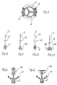
- Figures 7 through 11 show, by way of example, some versions of central support rotor for electric machines.
- the stator may have the desired number of inductors 2 (Figure 7), which encompass the rotor 1 with their air gap ( Figure 8).
- the rotor 1 ( Figure 9) can present a metallic ring 15 able to be magnetised and an inductor 23, external to the rotor 1.
- the flux of the inductor 23 is concatenated with the rotor 1 through the ring 15.
- the rotor 1 can have its moment of inertia increased by a flywheel mass 16 ( Figure 10) or it may have its induction enhanced by a pair of opposed inductors 24 ( Figure 11).
- Figures 12 and 13 show, by way of example, some versions of central support rotor for electric machines applied to servo-controls.
- the stator 2 interacts with a rotor limited in its extension to an annulus portion 17.
- To this annulus portion 17 is integral an arm connected to a pair of gears 32 ( Figure 12) or to a wheel and worm screw pair 33 ( Figure 13).
- Figures 14 through 18 show, by way of example, some versions of rotor with sliding guides for electric machines according to the invention.
- the stator can have the desired number of inductors 2 (Figure 14), which encompass the rotor 1 with their air gap ( Figure 8).
- the cavity inside the rotor can be used for the integration of the machine according to the invention with the desired utilisation.
- the rotor 1 ( Figure 15) can present internal sliding guides 3 and internal stator 2 and it can be provided with external mechanical transmission means, shown schematically as 34.
- the rotor 1 ( Figure 16) can present external sliding guides 3 and external stator 2 and it can be provided with internal mechanical transmission means, shown schematically as 34.
- Figures 17 and 18 schematically show two examples of the application shown, respectively, in Figures 15 and 16.
- the rotor presents internal sliding guides 3, four internal inductors 2 and on its outer periphery teeth for engagement with a chain 35.
- the rotor 1 presents, though they are not shown, external sliding guides, an external inductor 2 and on its inner periphery means 36 for connection with a drum 37.
- Figure 19 and 20 show a single stage machine according to the present invention, enclosed in a hollow cylinder casing 38, 39, and provided with internal connecting means for transmission, such as a flange 42 (Figure 19) and with external transmission means such as a crown gear 43 ( Figure 20). The compactness of the machine according to the invention is further shown.
Landscapes
- Engineering & Computer Science (AREA)
- Chemical & Material Sciences (AREA)
- Combustion & Propulsion (AREA)
- Power Engineering (AREA)
- Physics & Mathematics (AREA)
- Electromagnetism (AREA)
- Transportation (AREA)
- Mechanical Engineering (AREA)
- Connection Of Motors, Electrical Generators, Mechanical Devices, And The Like (AREA)
- Synchronous Machinery (AREA)
- Linear Motors (AREA)
- Reciprocating, Oscillating Or Vibrating Motors (AREA)
- Control Of Multiple Motors (AREA)
- Manufacture Of Motors, Generators (AREA)
Claims (9)
- Machine dynamoélectrique tournant par induction électromagnétique selon le principe des moteurs électriques linéaires, caractérisée en ce qu'elle possède un rotor annulaire (1) ayant la forme d'une couronne circulaire, lequel est muni d'au moins un rail circonférentiel (13, 14) en engagement avec des glissières, et un stator à bobine d'inductance (2) interagissant au moins avec une partie dudit rotor (1).
- Machine électromagnétique selon la revendication 1, caractérisée en ce que ledit rail circonférentiel (14) est à l'intérieur dudit stator (2).
- Machine électromagnétique selon la revendication 1, caractérisée en ce que ledit rail circonférentiel (13) est à l'extérieur dudit stator (2).
- Machine électromagnétique selon la revendication 1, caractérisée en ce que ledit stator (2) comporte au moins une bobine d'inductance (20) et un noyau électromagnétique (21) muni d'un entrefer traversé par ledit rotor.
- Machine électromagnétique selon la revendication 1, caractérisée en ce que ledit stator (2) comporte au moins une bobine d'inductance (23) et un noyau magnétique fermé, avec flux à travers ledit rotor (1).
- Machine électromagnétique selon la revendication 1, caractérisée en ce que ledit rotor annulaire (1) comporte une succession d'aimants permanents (10, 11) de polarités opposées avec ordre.
- Machine électromagnétique selon la revendication 1, caractérisée en ce que ledit rotor annulaire (5) comporte une succession de spires d'auto-induction (50:
- Machine électromagnétique selon la revendication 1, caractérisée en ce que ledit rotor annulaire (5) comporte une couronne de matière magnétisable (60) serrée entre deux couronnes opposées (61, 62) de matière non magnétisable.
- Machine électromagnétique selon la revendication 10, caractérisée en ce que ladite matière magnétisable est fer doux et ladite matière non magnétisable est un alliage d'aluminium.
Applications Claiming Priority (3)
| Application Number | Priority Date | Filing Date | Title |
|---|---|---|---|
| IT97RM000719A IT1297070B1 (it) | 1997-11-21 | 1997-11-21 | Macchina dinamoelettrica rotante a induzione elettromagnetica come agente in motori elettrici lineari. |
| ITRM970719 | 1997-11-21 | ||
| PCT/IT1998/000155 WO1999027635A1 (fr) | 1997-11-21 | 1998-06-11 | Machine dynamoelectrique tournant par induction electromagnetique de maniere a agir sur des moteurs electriques lineaires |
Publications (2)
| Publication Number | Publication Date |
|---|---|
| EP1032966A1 EP1032966A1 (fr) | 2000-09-06 |
| EP1032966B1 true EP1032966B1 (fr) | 2002-09-18 |
Family
ID=11405364
Family Applications (1)
| Application Number | Title | Priority Date | Filing Date |
|---|---|---|---|
| EP98929623A Expired - Lifetime EP1032966B1 (fr) | 1997-11-21 | 1998-06-11 | Machine dynamoelectrique tournant par induction electromagnetique selon le principe des moteurs electriques lineaires |
Country Status (10)
| Country | Link |
|---|---|
| US (1) | US6486582B1 (fr) |
| EP (1) | EP1032966B1 (fr) |
| CN (1) | CN1146098C (fr) |
| AT (1) | ATE224605T1 (fr) |
| AU (1) | AU7930398A (fr) |
| DE (1) | DE69808124T2 (fr) |
| ES (1) | ES2184286T3 (fr) |
| IT (1) | IT1297070B1 (fr) |
| RU (1) | RU2248080C2 (fr) |
| WO (1) | WO1999027635A1 (fr) |
Families Citing this family (29)
| Publication number | Priority date | Publication date | Assignee | Title |
|---|---|---|---|---|
| US6822369B2 (en) * | 2001-07-27 | 2004-11-23 | Ta-Ching Pong | Pulse propelling flat induction motor |
| GB0122732D0 (en) | 2001-09-20 | 2001-11-14 | Isis Innovations Ltd | Electromechanical transducer linear compressor and radio transmission antenna |
| MXPA04002810A (es) | 2001-09-26 | 2005-06-06 | Rheogene Holdings Inc | Acidos nucleicos receptores de ecdisona de saltarilla, polipeptidos, y sus usos. |
| US6703716B2 (en) * | 2001-10-17 | 2004-03-09 | Meng-Yu Liu | Permanent magnet generator for bicycle light operation |
| WO2003051551A1 (fr) * | 2001-12-14 | 2003-06-26 | Bültmann, Rudolf | Machine d'etirage a tambour |
| WO2003065551A1 (fr) * | 2002-02-01 | 2003-08-07 | Kabushiki Kaisha Shigen Kaihatsu Sha | Moteur electrique a ecartement axial |
| US6802385B2 (en) * | 2002-05-16 | 2004-10-12 | Wavecrest Laboratories, Llc | Electrically powered vehicles having motor and power supply contained within wheels |
| US6876122B2 (en) * | 2002-09-16 | 2005-04-05 | Lockheed Martin Corporation | Circular rail linear induction motor |
| US6765362B2 (en) * | 2002-11-15 | 2004-07-20 | Chang Ta-Shuo | Battery charging system for a personal mobile electrical apparatus |
| US20060186749A1 (en) * | 2002-12-05 | 2006-08-24 | Strydom Johannes M | Motor |
| WO2005060381A2 (fr) * | 2003-06-25 | 2005-07-07 | Advanced Propulsion Technologies | Generateur annulaire |
| US6899400B1 (en) * | 2003-08-05 | 2005-05-31 | Banner American Products, Inc. | Motorcycle wheel |
| US6942303B2 (en) * | 2003-09-23 | 2005-09-13 | Pacific Coast Wheel Factory, Inc. | Wheel assembly |
| DE10351485A1 (de) * | 2003-11-04 | 2005-06-09 | Zf Lenksysteme Gmbh | Fahrzeug-Hilfskraftlenkung mit Elektromotor |
| US6964454B1 (en) * | 2004-09-16 | 2005-11-15 | Miansian James K | Wheel with center spinner |
| CN101208853A (zh) * | 2005-03-23 | 2008-06-25 | 波峰实验室责任有限公司 | 电机及制造方法 |
| ATE407869T1 (de) * | 2006-02-15 | 2008-09-15 | Fiat Ricerche | Fahrzeugrad |
| US20070296313A1 (en) * | 2006-06-27 | 2007-12-27 | Leao Wang | Self-generating system for an exercise apparatus |
| US8222792B2 (en) * | 2006-08-04 | 2012-07-17 | Clean Current Limited Partnership | Axial air gap machine having stator and rotor discs formed of multiple detachable segments |
| US20110127887A1 (en) * | 2009-11-27 | 2011-06-02 | Chin-Sung Tsai | Generator for a bicycle |
| DE202011107060U1 (de) * | 2011-07-01 | 2012-10-09 | Dirk Strothmann | Vorrichtung zur berührungslosen Stromerzeugung, insbesondere Fahrraddynamo, Fahrzeugbeleuchtungsanlage und Fahrrad |
| US20120112461A1 (en) * | 2011-12-21 | 2012-05-10 | Earth Sure Renewable Energy Corporation | Dual use fan assembly for hvac systems and automotive systems to generate clean alternative elecric energy |
| RU2482920C1 (ru) * | 2012-02-24 | 2013-05-27 | Рустам Сагитович Аипов | Устройство для измельчения твердых материалов |
| US9061731B1 (en) * | 2012-10-15 | 2015-06-23 | Hung Do | Self-charging electric bicycle |
| CN107294352A (zh) * | 2016-11-29 | 2017-10-24 | 乐山市沙湾区薪火水箱制造有限公司 | 一种环形转子直流电机 |
| US10894573B2 (en) * | 2017-09-28 | 2021-01-19 | Pengjie Hu | Electric power-assist drive assembly for a spoked-wheeled vehicle |
| FR3084300B1 (fr) * | 2018-07-24 | 2021-05-21 | Univ Le Havre Normandie | Roue motorisee |
| EP3725658B1 (fr) * | 2019-04-19 | 2021-11-03 | H.E.R.S. S.r.l. | Bicyclette électrique avec accumulateur d'énergie électrique |
| US11211837B2 (en) | 2019-06-25 | 2021-12-28 | General Dynamics Land Systems—Canada | Actuator with individually computerized and networked electromagnetic poles |
Family Cites Families (18)
| Publication number | Priority date | Publication date | Assignee | Title |
|---|---|---|---|---|
| GB227845A (en) * | 1924-01-14 | 1925-07-30 | British Thomson Houston Co Ltd | Improvements in and relating to dynamo electric machines |
| US3355914A (en) * | 1964-11-02 | 1967-12-05 | Borg Warner | Clothes washing machine and linear motor therefor |
| GB1282485A (en) * | 1968-07-25 | 1972-07-19 | Ludwig F Meditz | Electric motor driven ducted fan assembly |
| DE2217466A1 (de) * | 1972-04-12 | 1973-10-18 | Ulrich Augustin | Induktionsmotor |
| FR2280229A1 (fr) * | 1974-07-23 | 1976-02-20 | Barbier Benard Turenne Anc Ets | Dispositif rotatif a moteur electrique lineaire |
| DE2506387A1 (de) * | 1975-02-15 | 1976-08-26 | Messerschmitt Boelkow Blohm | Fahrzeugantrieb in form eines linearmotors |
| DE2540908A1 (de) * | 1975-09-13 | 1977-03-17 | Krupp Gmbh | Dehnungsausgleich an wirbelstromantrieben |
| GB2094066A (en) * | 1981-01-08 | 1982-09-08 | Ask Jonas Waldemar | Electromagnetic machines |
| FR2511440B1 (fr) * | 1981-08-14 | 1989-01-27 | Anglo Amer Corp South Africa | Stockage cinetique d'energie a l'aide d'un volant |
| US4949000A (en) * | 1988-07-18 | 1990-08-14 | Mueller And Smith, Lpa | D.C. motor |
| JPH0288972A (ja) * | 1988-09-27 | 1990-03-29 | Shokichi Kumakura | 発電装置による自転車速度計 |
| EP0412509A3 (en) * | 1989-08-11 | 1992-02-26 | Ebara Corporation | Bearing structure |
| US5227702A (en) * | 1991-09-19 | 1993-07-13 | Nahirney Peter M | Direct current motor utilizing back electromotive force |
| US5203432A (en) * | 1991-11-15 | 1993-04-20 | Otis Elevator Company | Flat linear motor driven elevator |
| JPH06319251A (ja) * | 1992-11-17 | 1994-11-15 | Mitsubishi Electric Corp | 可変空隙型駆動装置 |
| US5474429A (en) * | 1994-01-11 | 1995-12-12 | Heidelberg; Goetz | Fluid-displacement apparatus especially a blower |
| US5696419A (en) * | 1994-06-13 | 1997-12-09 | Alternative Generation Devices, Inc. | High-efficiency electric power generator |
| US5874792A (en) * | 1997-06-10 | 1999-02-23 | Industrial Technology Research Institute | Bicycle generator |
-
1997
- 1997-11-21 IT IT97RM000719A patent/IT1297070B1/it active IP Right Grant
-
1998
- 1998-06-11 AT AT98929623T patent/ATE224605T1/de not_active IP Right Cessation
- 1998-06-11 EP EP98929623A patent/EP1032966B1/fr not_active Expired - Lifetime
- 1998-06-11 AU AU79303/98A patent/AU7930398A/en not_active Abandoned
- 1998-06-11 US US09/554,846 patent/US6486582B1/en not_active Expired - Fee Related
- 1998-06-11 DE DE69808124T patent/DE69808124T2/de not_active Expired - Lifetime
- 1998-06-11 ES ES98929623T patent/ES2184286T3/es not_active Expired - Lifetime
- 1998-06-11 RU RU2000115806/09A patent/RU2248080C2/ru not_active IP Right Cessation
- 1998-06-11 CN CNB988124645A patent/CN1146098C/zh not_active Expired - Fee Related
- 1998-06-11 WO PCT/IT1998/000155 patent/WO1999027635A1/fr not_active Ceased
Also Published As
| Publication number | Publication date |
|---|---|
| IT1297070B1 (it) | 1999-08-03 |
| AU7930398A (en) | 1999-06-15 |
| EP1032966A1 (fr) | 2000-09-06 |
| ES2184286T3 (es) | 2003-04-01 |
| RU2248080C2 (ru) | 2005-03-10 |
| WO1999027635A1 (fr) | 1999-06-03 |
| ITRM970719A1 (it) | 1999-05-21 |
| US6486582B1 (en) | 2002-11-26 |
| DE69808124D1 (de) | 2002-10-24 |
| CN1146098C (zh) | 2004-04-14 |
| DE69808124T2 (de) | 2003-05-15 |
| CN1282458A (zh) | 2001-01-31 |
| ATE224605T1 (de) | 2002-10-15 |
Similar Documents
| Publication | Publication Date | Title |
|---|---|---|
| EP1032966B1 (fr) | Machine dynamoelectrique tournant par induction electromagnetique selon le principe des moteurs electriques lineaires | |
| CA2538716C (fr) | Moteur a reducteur planetaire | |
| KR100807853B1 (ko) | 다이나모 일렉트릭 장치 | |
| US4980595A (en) | Multiple magnetic paths machine | |
| CN100423408C (zh) | 模块化、横向磁通的旋转电动机及其制造方法 | |
| US6891302B1 (en) | Light-weight high-power electrical machine | |
| EP0798842A1 (fr) | Moteur à aimants | |
| US20080246362A1 (en) | Radial airgap, transverse flux machine | |
| US20090072639A1 (en) | Segmented composite rotor | |
| US20110115326A1 (en) | Electrical machines | |
| US20110273035A1 (en) | Transverse and/or commutated flux system stator concepts | |
| US20040251761A1 (en) | Radial airgap, transverse flux motor | |
| EP2250724A2 (fr) | Groupe motopropulseur d'éolienne | |
| US6037690A (en) | Energy conversion system mounted in a wheel hub | |
| WO2009036402A2 (fr) | Machines électromécaniques composites à aimants uniformes | |
| WO2003047067A2 (fr) | Machine electrique | |
| WO2008076568A2 (fr) | Machine électrique double face à deux arbres | |
| EP1488495A1 (fr) | Moteur electrique integre dans une roue de vehicule | |
| US7325637B2 (en) | Hybrid drive device | |
| RU2690666C1 (ru) | Электрическая машина с поперечным магнитным потоком (варианты) | |
| US20240171056A1 (en) | Electric circulatory leverage drive method and apparatus | |
| JP2000515093A (ja) | 車軸ハブ取り付け式のエネルギー変換装置 | |
| RU16046U1 (ru) | Вентильная электрическая машина | |
| CN1109650A (zh) | 一种新型的发电机 | |
| KR200230732Y1 (ko) | 전동 차량용 축방향 자속 브러시리스 직류전동기 |
Legal Events
| Date | Code | Title | Description |
|---|---|---|---|
| PUAI | Public reference made under article 153(3) epc to a published international application that has entered the european phase |
Free format text: ORIGINAL CODE: 0009012 |
|
| 17P | Request for examination filed |
Effective date: 20000517 |
|
| AK | Designated contracting states |
Kind code of ref document: A1 Designated state(s): AT BE CH DE DK ES FR GB GR IE IT LI LU MC NL PT SE |
|
| GRAG | Despatch of communication of intention to grant |
Free format text: ORIGINAL CODE: EPIDOS AGRA |
|
| 17Q | First examination report despatched |
Effective date: 20011218 |
|
| GRAG | Despatch of communication of intention to grant |
Free format text: ORIGINAL CODE: EPIDOS AGRA |
|
| GRAH | Despatch of communication of intention to grant a patent |
Free format text: ORIGINAL CODE: EPIDOS IGRA |
|
| GRAH | Despatch of communication of intention to grant a patent |
Free format text: ORIGINAL CODE: EPIDOS IGRA |
|
| GRAA | (expected) grant |
Free format text: ORIGINAL CODE: 0009210 |
|
| AK | Designated contracting states |
Kind code of ref document: B1 Designated state(s): AT BE CH DE DK ES FR GB GR IE IT LI LU MC NL PT SE |
|
| PG25 | Lapsed in a contracting state [announced via postgrant information from national office to epo] |
Ref country code: NL Free format text: LAPSE BECAUSE OF FAILURE TO SUBMIT A TRANSLATION OF THE DESCRIPTION OR TO PAY THE FEE WITHIN THE PRESCRIBED TIME-LIMIT Effective date: 20020918 Ref country code: LI Free format text: LAPSE BECAUSE OF FAILURE TO SUBMIT A TRANSLATION OF THE DESCRIPTION OR TO PAY THE FEE WITHIN THE PRESCRIBED TIME-LIMIT Effective date: 20020918 Ref country code: IT Free format text: LAPSE BECAUSE OF FAILURE TO SUBMIT A TRANSLATION OF THE DESCRIPTION OR TO PAY THE FEE WITHIN THE PRE;WARNING: LAPSES OF ITALIAN PATENTS WITH EFFECTIVE DATE BEFORE 2007 MAY HAVE OCCURRED AT ANY TIME BEFORE 2007. THE CORRECT EFFECTIVE DATE MAY BE DIFFERENT FROM THE ONE RECORDED.SCRIBED TIME-LIMIT Effective date: 20020918 Ref country code: GR Free format text: LAPSE BECAUSE OF FAILURE TO SUBMIT A TRANSLATION OF THE DESCRIPTION OR TO PAY THE FEE WITHIN THE PRESCRIBED TIME-LIMIT Effective date: 20020918 Ref country code: CH Free format text: LAPSE BECAUSE OF FAILURE TO SUBMIT A TRANSLATION OF THE DESCRIPTION OR TO PAY THE FEE WITHIN THE PRESCRIBED TIME-LIMIT Effective date: 20020918 Ref country code: BE Free format text: LAPSE BECAUSE OF FAILURE TO SUBMIT A TRANSLATION OF THE DESCRIPTION OR TO PAY THE FEE WITHIN THE PRESCRIBED TIME-LIMIT Effective date: 20020918 Ref country code: AT Free format text: LAPSE BECAUSE OF FAILURE TO SUBMIT A TRANSLATION OF THE DESCRIPTION OR TO PAY THE FEE WITHIN THE PRESCRIBED TIME-LIMIT Effective date: 20020918 |
|
| REF | Corresponds to: |
Ref document number: 224605 Country of ref document: AT Date of ref document: 20021015 Kind code of ref document: T |
|
| REG | Reference to a national code |
Ref country code: GB Ref legal event code: FG4D |
|
| REG | Reference to a national code |
Ref country code: CH Ref legal event code: EP |
|
| REG | Reference to a national code |
Ref country code: IE Ref legal event code: FG4D |
|
| REF | Corresponds to: |
Ref document number: 69808124 Country of ref document: DE Date of ref document: 20021024 |
|
| PG25 | Lapsed in a contracting state [announced via postgrant information from national office to epo] |
Ref country code: SE Free format text: LAPSE BECAUSE OF FAILURE TO SUBMIT A TRANSLATION OF THE DESCRIPTION OR TO PAY THE FEE WITHIN THE PRESCRIBED TIME-LIMIT Effective date: 20021218 Ref country code: DK Free format text: LAPSE BECAUSE OF FAILURE TO SUBMIT A TRANSLATION OF THE DESCRIPTION OR TO PAY THE FEE WITHIN THE PRESCRIBED TIME-LIMIT Effective date: 20021218 |
|
| PG25 | Lapsed in a contracting state [announced via postgrant information from national office to epo] |
Ref country code: PT Free format text: LAPSE BECAUSE OF FAILURE TO SUBMIT A TRANSLATION OF THE DESCRIPTION OR TO PAY THE FEE WITHIN THE PRESCRIBED TIME-LIMIT Effective date: 20021219 |
|
| NLV1 | Nl: lapsed or annulled due to failure to fulfill the requirements of art. 29p and 29m of the patents act | ||
| REG | Reference to a national code |
Ref country code: ES Ref legal event code: FG2A Ref document number: 2184286 Country of ref document: ES Kind code of ref document: T3 |
|
| ET | Fr: translation filed | ||
| REG | Reference to a national code |
Ref country code: CH Ref legal event code: PL |
|
| PG25 | Lapsed in a contracting state [announced via postgrant information from national office to epo] |
Ref country code: LU Free format text: LAPSE BECAUSE OF NON-PAYMENT OF DUE FEES Effective date: 20030611 Ref country code: IE Free format text: LAPSE BECAUSE OF NON-PAYMENT OF DUE FEES Effective date: 20030611 |
|
| PG25 | Lapsed in a contracting state [announced via postgrant information from national office to epo] |
Ref country code: MC Free format text: LAPSE BECAUSE OF NON-PAYMENT OF DUE FEES Effective date: 20030630 |
|
| PLBE | No opposition filed within time limit |
Free format text: ORIGINAL CODE: 0009261 |
|
| STAA | Information on the status of an ep patent application or granted ep patent |
Free format text: STATUS: NO OPPOSITION FILED WITHIN TIME LIMIT |
|
| 26N | No opposition filed |
Effective date: 20030619 |
|
| REG | Reference to a national code |
Ref country code: IE Ref legal event code: MM4A |
|
| PGFP | Annual fee paid to national office [announced via postgrant information from national office to epo] |
Ref country code: ES Payment date: 20100723 Year of fee payment: 13 |
|
| PGFP | Annual fee paid to national office [announced via postgrant information from national office to epo] |
Ref country code: GB Payment date: 20100630 Year of fee payment: 13 Ref country code: FR Payment date: 20100723 Year of fee payment: 13 Ref country code: DE Payment date: 20100830 Year of fee payment: 13 |
|
| GBPC | Gb: european patent ceased through non-payment of renewal fee |
Effective date: 20110611 |
|
| REG | Reference to a national code |
Ref country code: FR Ref legal event code: ST Effective date: 20120229 |
|
| REG | Reference to a national code |
Ref country code: DE Ref legal event code: R119 Ref document number: 69808124 Country of ref document: DE Effective date: 20120103 |
|
| PG25 | Lapsed in a contracting state [announced via postgrant information from national office to epo] |
Ref country code: DE Free format text: LAPSE BECAUSE OF NON-PAYMENT OF DUE FEES Effective date: 20120103 Ref country code: FR Free format text: LAPSE BECAUSE OF NON-PAYMENT OF DUE FEES Effective date: 20110630 |
|
| PG25 | Lapsed in a contracting state [announced via postgrant information from national office to epo] |
Ref country code: GB Free format text: LAPSE BECAUSE OF NON-PAYMENT OF DUE FEES Effective date: 20110611 |
|
| REG | Reference to a national code |
Ref country code: ES Ref legal event code: FD2A Effective date: 20130417 |
|
| PG25 | Lapsed in a contracting state [announced via postgrant information from national office to epo] |
Ref country code: ES Free format text: LAPSE BECAUSE OF NON-PAYMENT OF DUE FEES Effective date: 20110612 |