EP1033096A1 - Cadre pour un siege ou pour un lit - Google Patents
Cadre pour un siege ou pour un lit Download PDFInfo
- Publication number
- EP1033096A1 EP1033096A1 EP99810187A EP99810187A EP1033096A1 EP 1033096 A1 EP1033096 A1 EP 1033096A1 EP 99810187 A EP99810187 A EP 99810187A EP 99810187 A EP99810187 A EP 99810187A EP 1033096 A1 EP1033096 A1 EP 1033096A1
- Authority
- EP
- European Patent Office
- Prior art keywords
- frame
- frame part
- lever
- frame according
- guide surface
- Prior art date
- Legal status (The legal status is an assumption and is not a legal conclusion. Google has not performed a legal analysis and makes no representation as to the accuracy of the status listed.)
- Withdrawn
Links
- 230000005540 biological transmission Effects 0.000 claims description 11
- 230000006835 compression Effects 0.000 claims description 10
- 238000007906 compression Methods 0.000 claims description 10
- 230000007423 decrease Effects 0.000 claims description 2
- 238000012546 transfer Methods 0.000 description 3
- 230000003187 abdominal effect Effects 0.000 description 2
- 238000013459 approach Methods 0.000 description 2
- 230000009286 beneficial effect Effects 0.000 description 1
- 238000013461 design Methods 0.000 description 1
- 238000006073 displacement reaction Methods 0.000 description 1
- 230000000694 effects Effects 0.000 description 1
- 238000012986 modification Methods 0.000 description 1
- 230000004048 modification Effects 0.000 description 1
- 230000029058 respiratory gaseous exchange Effects 0.000 description 1
- 230000000630 rising effect Effects 0.000 description 1
- 238000012549 training Methods 0.000 description 1
Images


Classifications
-
- A—HUMAN NECESSITIES
- A47—FURNITURE; DOMESTIC ARTICLES OR APPLIANCES; COFFEE MILLS; SPICE MILLS; SUCTION CLEANERS IN GENERAL
- A47C—CHAIRS; SOFAS; BEDS
- A47C20/00—Head-, foot- or like rests for beds, sofas or the like
- A47C20/08—Head-, foot- or like rests for beds, sofas or the like with means for adjusting two or more rests simultaneously
-
- A—HUMAN NECESSITIES
- A47—FURNITURE; DOMESTIC ARTICLES OR APPLIANCES; COFFEE MILLS; SPICE MILLS; SUCTION CLEANERS IN GENERAL
- A47C—CHAIRS; SOFAS; BEDS
- A47C20/00—Head-, foot- or like rests for beds, sofas or the like
- A47C20/04—Head-, foot- or like rests for beds, sofas or the like with adjustable inclination
- A47C20/048—Head-, foot- or like rests for beds, sofas or the like with adjustable inclination by fluid means
Definitions
- the invention relates to a frame for a couch or Seating furniture according to the preamble of claim 1.
- a such a frame usually forms a basis for one Upholstery pad that is fixed or removable attached to it or can only be hung up.
- the frame can be part of a Bed, a lounger, a deck chair or the like his.
- a generic frame is from DE-A-29 40 364 known.
- the lower frame is on his Foot end also anchored in the base frame, see above that its front end can be lowered.
- On both long sides a transmission device is provided in each case, consisting of one at the rear end of the upper frame part attached pin that is in a substantially horizontal, Slit slightly bent upwards at the rear end of the lower frame engages. Lowering the latter thus causes a via the transmission device Erection of the upper frame part, d. H. a swivel, at the head end of which is raised.
- the pen slides while in the slot against its front end, while the rear end of the frame top and the front end of the Remove the lower part of the frame slightly.
- the Erection of the upper part of the frame is supported by a Tension spring, which is anchored to the base frame and on one Approach of the top frame attacks.
- a pivot bearing is indeed a Upper part of the frame by means of two levers of different lengths are hinged to a base frame and on Attack frame top known, in which one Erection of the upper frame part with a sufficient Increasing the distance between its rear end and the front end of a subsequent lower frame part is guaranteed, but there is support from the Erection of the upper part of the frame by lowering the Lower frame not provided. Under these circumstances The tension springs used are in turn for a comfortable Erection of the upper part of the frame is not sufficient.
- the AT-B-401 604 shows a couch, in which a turn Top frame around one opposite its rear end transverse axis offset at the head, swiveling in one Base frame is anchored. His rear end is with that Front end of a lower frame part pivotally connected swiveling at the foot end and at the same time longitudinally displaceable in the Base frame is stored.
- a gas pressure spring is provided on the upper part of the frame on one attached to the underside of the upper frame part, attacks on the rear end of the protruding projection and approximately in the area of the foot end of the lower frame part on Base frame is supported.
- the invention is based on the object Generic frame so that the body no unpleasant burdens on the user, in particular Upsetting is exposed.
- the upper part of the frame which is required for this purpose, however also a comfortable erection of the Upper part of the frame if possible without external energy supply to be guaranteed.
- the erection of the Upper part of the frame by simultaneously lowering the Lower frame part that has a suitable Transmission device acts on the former, be helped.
- support is provided by a suitable and suitably used spring element required.
- the task of the invention is characterized by the features in the indicator of claim 1 solved.
- the invention provides a framework created for a couch or seating furniture, in which the Erection of the frame top in every respect comfortably and is easy to do and the user doesn't Is exposed to loads of any kind. this applies largely independent of weight and height.
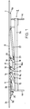
- the frame shown for example for a bed includes (Fig. 1, 2) a base frame 1 with two longitudinal spars 2a, b, which with cross bars 3a, b form a square that is supported on feet 4a, b, c, d.
- At the top and bottom are supports 5a, b on the square attached, on which a frame upper part 6 in the Basic position rests or a foot part 7 is attached.
- the foot end of a lower frame part 8 is down pivotably connected to the foot part 7, so that its Front end, to the rear end of the upper frame part 6 from the basic position, in which it is just like that Frame top 6 is horizontal and with the same and Foot part 7 a flat surface for receiving a mattress forms, can be lowered.
- the frame top 6, the Lower frame part 8 and the foot part 7 are each as rectangular plates.
- the upper frame part 6 is on both long sides of the Base frame with the same via a pivot bearing 9a or 9b connected. This is done by a first lever 10 and a longer second lever 11 is formed.
- the first Lever 10 engages one near the rear of the Frame top 6 lying attack point 12 where he is pivotally connected to the same and is at one offset from the attack point 12 on the head side Articulation point 13 articulated on the respective longitudinal spar 2a; b, see above that the first lever 10 in the basic position of the Frame upper part 6 slightly backwards against that Lower frame part 8 is inclined.
- the second lever 11 with the upper frame part 6 and the respective Longitudinal spar 2a; b connected.
- His point of attack 14 at the former is opposite the point of attack 12 of the first lever 10 offset on the head side, as well as its articulation point 15 opposite the pivot point 13 of the same.
- the distance between the Articulation points 13, 15 is approximately 2.5 times the Distance between the points of attack 12, 14, so that the second lever 11 in the basic position much stronger is inclined as the first lever 10.
- the connecting lines between the points of attack 12, 14 on the one hand and the Articulation points 13, 15 on the other hand are in the basic position parallel, so that together with the levers 10, 11 a form a crooked trapezoid.
- Each of the Transmission devices 16a, b comprises (see also FIG. 4a) one in the area of its front end at the bottom of the Attached lower frame part 8, over the front end protruding guide plate 17, the underside of which is in Downwardly convex guide surface 18 extending in the longitudinal direction forms.
- the guide plate 17 has approximately the shape of a Circle segment. However, at the foot end area Curvature of the guide surface 18 somewhat stronger than on the head side End area. As a counterpart to this is at the bottom of the Frame top part 6 each has an extension 19 attached protrudes beyond the rear end. It carries at its end a rotatably mounted roller 20 which has a stop forms, which bears against the guide surface 18.
- the two extensions are connected by a cross bar 21 (Fig. 2) connected to which a lockable gas pressure spring 22nd attacks the center in the longitudinal direction below the Lower frame part 8 is arranged and down to the Foot part 7 extends where it is supported on the base frame 1 is.
- a cross bar 21 Fig. 2
- a lockable gas pressure spring 22nd attacks the center in the longitudinal direction below the Lower frame part 8 is arranged and down to the Foot part 7 extends where it is supported on the base frame 1 is.
- At the end of the cylinder of the gas pressure spring 22 is one shorter coil spring 23 attached, which in the Basic position between the cylinder and a joint on End of the piston of the gas pressure spring 22 is compressed.
- the Gas pressure spring 22 and the coil spring 23 form together a compression spring element in one to the basic position then up to a swivel angle of the Upper part 6 of between 20 ° and 30 °, in particular about 25 ° extending initial interval is a relatively large Has spring constant and at larger swivel angles, when the coil spring 23 has reached its rest position and only the gas pressure spring 22 is effective, one much smaller.
- the upper frame part 6 carries at its head end as rectangular plate formed hinged Headboard 24 with a shoulder 25, on which one on Frame upper part 6 supported centrally arranged Gas spring 26 attacks.
- the pivoting of the upper frame part 6 corresponds to this a rotation about a transverse to the longitudinal direction virtual axis of rotation, which during the pivoting something shifts, but always about Bisector between the upper frame part 6 and the Lower frame part 8 and slightly above the latter.
- the average distance of the virtual axis of rotation from the likewise virtual intersection line through the Frame upper part 6 and the lower frame part 8 defined Levels preferably correspond to the thickness of one any upholstery pad plus about 10 cm to 20 cm.
- the erection of the Frame upper part 6 also by lowering the front end of the lower frame part 8 and the transmission devices 16a, b, which the weight of the lower frame part 8 and before convert everything of the user of the bed into a torque, that the pivoting of the upper frame part 6 clockwise supported.
- the guide surface 18 presses on each Roll 20 at the end of the extension 19. As best seen in Fig. 4a-c visible, moves in the course of the pivoting of the Frame top 6, the point at which the roller 20 Guiding surface 18 touches, from the foot end of the latter towards its head end, while the front end of the Lower frame part 8 lowers.
- the ratio is determined by the convex shape of the guide surface 18 between the pivoting of the upper frame part 6 and the Lowering of the lower frame part 8 at the beginning of the movement, if the roller 20 the sinking part of the guide surface 18th follows, considerably enlarged, towards the end of the same towards when the roller has the rising part of the guide surface 18 has reached, but weakened. This will u. a. the changing leverage and increasing inclination of the lower frame part 8 taken into account. Because of the Roll 20 stop formed the pivoting of the Frame upper part 6 only on one side against smaller swivel angles limited, so only its pivoting by one Forces minimum swivel angle, it is always possible that Frame upper part 6 regardless of the lowering of the Erect lower frame part 8 by external influence.
- the upper frame part 6 can in the example shown an area swiveled by an area Maximum angle of 60 ° is limited upwards, however In principle, larger maximum angles are also possible. It can in every intermediate position, e.g. B. in Fig. 4b illustrated, can be fixed by the gas pressure spring 22nd is locked.
- the head part 24 can also be released by releasing the locking Gas spring 26 pivoted upwards (see FIG. 3) and through light pressure with the head in the basic position in which it is forms a flat surface with the upper frame part 6, be pivoted back.
- the transmission devices 16a, b can the needs are matched.
- An essential one The relationship between the lowering of the Frame lower part 8, the z. B. by the angle of the same Horizontal can be parameterized, and the Minimum pivot angle of the upper frame part 6, since it is the Ratio between that on the front end of the Frame lower part 8 acting weight and that over the Transfer devices 16a, b to the upper frame part 6 exerted torque determined.
- the said relationship can be achieved through training the Guide surface 18 can be set over a wide range. It is also conceivable that the guide plates 17 and possibly the Make extensions 19 interchangeable and so precise Attitude to the needs and desires of each Allow user. For the gas spring 22 and the Coil spring 23 are also of different types different characteristics available can be interchanged. In addition can the effect of the compression spring element made adjustable be by the base point or the point of attack slidable.
- a transmission device on the lower frame part attached stop be it a roll or a Slider, include the one with the frame top connected upward-facing guide surface cooperates.
Landscapes
- Health & Medical Sciences (AREA)
- General Health & Medical Sciences (AREA)
- Nursing (AREA)
- Invalid Beds And Related Equipment (AREA)
- Special Chairs (AREA)
- Seats For Vehicles (AREA)
- Chairs For Special Purposes, Such As Reclining Chairs (AREA)
- Paints Or Removers (AREA)
- Orthopedics, Nursing, And Contraception (AREA)
Priority Applications (6)
| Application Number | Priority Date | Filing Date | Title |
|---|---|---|---|
| EP99810187A EP1033096A1 (fr) | 1999-03-04 | 1999-03-04 | Cadre pour un siege ou pour un lit |
| PCT/EP2000/001567 WO2000051468A1 (fr) | 1999-03-04 | 2000-02-25 | Cadre pour siege ou fauteuil inclinable |
| DE50004478T DE50004478D1 (de) | 1999-03-04 | 2000-02-25 | Rahmen für ein liege- oder sitzmöbel |
| AT00912506T ATE254420T1 (de) | 1999-03-04 | 2000-02-25 | Rahmen für ein liege- oder sitzmöbel |
| EP00912506A EP1076497B1 (fr) | 1999-03-04 | 2000-02-25 | Cadre pour siege ou fauteuil inclinable |
| AU34249/00A AU3424900A (en) | 1999-03-04 | 2000-02-25 | Frame for a recliner or seat |
Applications Claiming Priority (1)
| Application Number | Priority Date | Filing Date | Title |
|---|---|---|---|
| EP99810187A EP1033096A1 (fr) | 1999-03-04 | 1999-03-04 | Cadre pour un siege ou pour un lit |
Publications (1)
| Publication Number | Publication Date |
|---|---|
| EP1033096A1 true EP1033096A1 (fr) | 2000-09-06 |
Family
ID=8242708
Family Applications (2)
| Application Number | Title | Priority Date | Filing Date |
|---|---|---|---|
| EP99810187A Withdrawn EP1033096A1 (fr) | 1999-03-04 | 1999-03-04 | Cadre pour un siege ou pour un lit |
| EP00912506A Expired - Lifetime EP1076497B1 (fr) | 1999-03-04 | 2000-02-25 | Cadre pour siege ou fauteuil inclinable |
Family Applications After (1)
| Application Number | Title | Priority Date | Filing Date |
|---|---|---|---|
| EP00912506A Expired - Lifetime EP1076497B1 (fr) | 1999-03-04 | 2000-02-25 | Cadre pour siege ou fauteuil inclinable |
Country Status (5)
| Country | Link |
|---|---|
| EP (2) | EP1033096A1 (fr) |
| AT (1) | ATE254420T1 (fr) |
| AU (1) | AU3424900A (fr) |
| DE (1) | DE50004478D1 (fr) |
| WO (1) | WO2000051468A1 (fr) |
Citations (6)
| Publication number | Priority date | Publication date | Assignee | Title |
|---|---|---|---|---|
| DE2749152B1 (de) * | 1977-11-03 | 1978-08-03 | Hans Segmueller | Bett mit in der Neigung stufenlos verstellbarer Kopfstuetze |
| DE2940364A1 (de) * | 1979-10-05 | 1981-04-23 | Guenther Boehme | Verstellbares sitz- und liegemoebel |
| FR2700109A1 (fr) * | 1993-01-07 | 1994-07-08 | Renault Creations Andre | Perfectionnement aux sommiers à dosseret relevable pour literie. |
| FR2714805A1 (fr) * | 1994-01-12 | 1995-07-13 | Dievart Rene Charles | Sommier de lit à profil longitudinal réglable. |
| DE29718236U1 (de) * | 1997-10-15 | 1998-11-19 | OPTIMO Möbelhandelsgesellschaft mbH, 84359 Simbach | Gelenkbeschlag für Lattenroste |
| EP0895738A1 (fr) * | 1997-08-05 | 1999-02-10 | Oniris S.A. | Sommier déformable à profil déclive et ergonomique |
Family Cites Families (1)
| Publication number | Priority date | Publication date | Assignee | Title |
|---|---|---|---|---|
| AT401604B (de) | 1995-01-11 | 1996-10-25 | Optimo Holz Und Drahtbearbeitu | Betteinsatz |
-
1999
- 1999-03-04 EP EP99810187A patent/EP1033096A1/fr not_active Withdrawn
-
2000
- 2000-02-25 AT AT00912506T patent/ATE254420T1/de not_active IP Right Cessation
- 2000-02-25 WO PCT/EP2000/001567 patent/WO2000051468A1/fr not_active Ceased
- 2000-02-25 EP EP00912506A patent/EP1076497B1/fr not_active Expired - Lifetime
- 2000-02-25 DE DE50004478T patent/DE50004478D1/de not_active Expired - Fee Related
- 2000-02-25 AU AU34249/00A patent/AU3424900A/en not_active Abandoned
Patent Citations (6)
| Publication number | Priority date | Publication date | Assignee | Title |
|---|---|---|---|---|
| DE2749152B1 (de) * | 1977-11-03 | 1978-08-03 | Hans Segmueller | Bett mit in der Neigung stufenlos verstellbarer Kopfstuetze |
| DE2940364A1 (de) * | 1979-10-05 | 1981-04-23 | Guenther Boehme | Verstellbares sitz- und liegemoebel |
| FR2700109A1 (fr) * | 1993-01-07 | 1994-07-08 | Renault Creations Andre | Perfectionnement aux sommiers à dosseret relevable pour literie. |
| FR2714805A1 (fr) * | 1994-01-12 | 1995-07-13 | Dievart Rene Charles | Sommier de lit à profil longitudinal réglable. |
| EP0895738A1 (fr) * | 1997-08-05 | 1999-02-10 | Oniris S.A. | Sommier déformable à profil déclive et ergonomique |
| DE29718236U1 (de) * | 1997-10-15 | 1998-11-19 | OPTIMO Möbelhandelsgesellschaft mbH, 84359 Simbach | Gelenkbeschlag für Lattenroste |
Also Published As
| Publication number | Publication date |
|---|---|
| ATE254420T1 (de) | 2003-12-15 |
| EP1076497A1 (fr) | 2001-02-21 |
| DE50004478D1 (de) | 2003-12-24 |
| EP1076497B1 (fr) | 2003-11-19 |
| AU3424900A (en) | 2000-09-21 |
| WO2000051468A1 (fr) | 2000-09-08 |
Similar Documents
| Publication | Publication Date | Title |
|---|---|---|
| EP0363833B1 (fr) | Chaise, en particulier chaise de bureau | |
| DE3103188A1 (de) | Verstellbarer lehnstuhl | |
| DE2848313C2 (de) | Untermatratze für Liegemöbel | |
| WO2008000207A1 (fr) | Dossier destiné à une chaise ou à un fauteuil et chaise ou fauteuil pourvu d'un tel dossier | |
| DE3124767A1 (de) | Rahmengeruest fuer einen stuhl | |
| DE102005051236B4 (de) | Sessel | |
| DE4219599C2 (de) | Synchronverstelleinrichtung für Bürostühle oder dergleichen | |
| EP1632152A2 (fr) | Meuble d'assise | |
| EP1076497B1 (fr) | Cadre pour siege ou fauteuil inclinable | |
| DE7630781U1 (de) | Stuhl, sessel oder dergleichen sitzmoebel | |
| DE102009007324A1 (de) | Fußeinrichtung mit senkrechter Schwenkachse | |
| AT509542B1 (de) | Gelenkbeschlag für sitzmöbel | |
| DE3009073C2 (de) | Verstellbares Liegemöbel | |
| AT408309B (de) | Sitz-liege-möbel | |
| DE10307738B4 (de) | Neigungsverstellvorrichtung für mindestens einen Teil einer Liege- oder Sitzfläche | |
| DE19901127C2 (de) | Kranken- oder Pflegebett | |
| DE701339C (de) | Einstellvorrichtung fuer zwei sich kreuzende Gestellteile eines verstellbaren Sitzliegemoebels | |
| DE3239356A1 (de) | Sitz fuer einen stuhl, sessel oder dgl. | |
| DE2259010A1 (de) | Einstellbarer stuhl | |
| DE87044C (fr) | ||
| DE8804868U1 (de) | Tisch, insbesondere Schreibtisch | |
| EP4470422A1 (fr) | Meuble d'assise et ferrure associée | |
| DE1529449C (de) | Liegemöbel | |
| DE9210365U1 (de) | Sanitätsstuhl | |
| DE3800756C2 (fr) |
Legal Events
| Date | Code | Title | Description |
|---|---|---|---|
| PUAI | Public reference made under article 153(3) epc to a published international application that has entered the european phase |
Free format text: ORIGINAL CODE: 0009012 |
|
| AK | Designated contracting states |
Kind code of ref document: A1 Designated state(s): AT BE CH CY DE DK ES FI FR GB GR IE IT LI LU MC NL PT SE |
|
| AX | Request for extension of the european patent |
Free format text: AL;LT;LV;MK;RO;SI |
|
| AKX | Designation fees paid | ||
| STAA | Information on the status of an ep patent application or granted ep patent |
Free format text: STATUS: THE APPLICATION IS DEEMED TO BE WITHDRAWN |
|
| 18D | Application deemed to be withdrawn |
Effective date: 20010307 |
|
| REG | Reference to a national code |
Ref country code: DE Ref legal event code: 8566 |