EP1033159A2 - Spielzeug mit einer selbstbewegenden Spielzeugfigur - Google Patents
Spielzeug mit einer selbstbewegenden Spielzeugfigur Download PDFInfo
- Publication number
- EP1033159A2 EP1033159A2 EP00200778A EP00200778A EP1033159A2 EP 1033159 A2 EP1033159 A2 EP 1033159A2 EP 00200778 A EP00200778 A EP 00200778A EP 00200778 A EP00200778 A EP 00200778A EP 1033159 A2 EP1033159 A2 EP 1033159A2
- Authority
- EP
- European Patent Office
- Prior art keywords
- toy
- parts
- motor means
- supporting
- base
- Prior art date
- Legal status (The legal status is an assumption and is not a legal conclusion. Google has not performed a legal analysis and makes no representation as to the accuracy of the status listed.)
- Withdrawn
Links
- 230000005236 sound signal Effects 0.000 claims abstract description 19
- 230000005291 magnetic effect Effects 0.000 claims description 19
- 230000002441 reversible effect Effects 0.000 claims description 5
- 210000004197 pelvis Anatomy 0.000 claims description 2
- 230000005294 ferromagnetic effect Effects 0.000 claims 1
- 239000007769 metal material Substances 0.000 claims 1
- 230000004913 activation Effects 0.000 abstract description 3
- 235000001674 Agaricus brunnescens Nutrition 0.000 description 6
- 230000003252 repetitive effect Effects 0.000 description 5
- 239000003302 ferromagnetic material Substances 0.000 description 4
- 230000009471 action Effects 0.000 description 3
- 230000000694 effects Effects 0.000 description 3
- 241000282414 Homo sapiens Species 0.000 description 2
- 230000008901 benefit Effects 0.000 description 2
- 239000003638 chemical reducing agent Substances 0.000 description 2
- 239000012777 electrically insulating material Substances 0.000 description 2
- 230000002269 spontaneous effect Effects 0.000 description 2
- 241001465754 Metazoa Species 0.000 description 1
- 230000005611 electricity Effects 0.000 description 1
- 239000012530 fluid Substances 0.000 description 1
- 230000006870 function Effects 0.000 description 1
- 230000005484 gravity Effects 0.000 description 1
- 230000002452 interceptive effect Effects 0.000 description 1
- 230000007246 mechanism Effects 0.000 description 1
- 230000004048 modification Effects 0.000 description 1
- 238000012986 modification Methods 0.000 description 1
- 230000008450 motivation Effects 0.000 description 1
- 230000004044 response Effects 0.000 description 1
Images


Classifications
-
- A—HUMAN NECESSITIES
- A63—SPORTS; GAMES; AMUSEMENTS
- A63H—TOYS, e.g. TOPS, DOLLS, HOOPS OR BUILDING BLOCKS
- A63H13/00—Toy figures with self-moving parts, with or without movement of the toy as a whole
Definitions
- the present invention relates to a toy comprising a self-moving toy-figure having at least two parts connected together by a joint in such a way as to be capable of relative motion, that is to say they are articulated.
- toy-figure is intended to denote both toy-figures having the resemblance of a human being or living creature in general, such as a doll or animal, and other kinds, for example a marionette, a dummy and so forth.
- the problem addressed by the present invention is how to devise a toy comprising a self-moving toy-figure having structural and functional features such as to satisfy the abovementioned demands and at the same time to obviate the problems spoken of with respect to the toy-figures of the prior art.
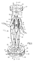
- the number 1 is a general reference for a toy according to the invention comprising a self-moving toy-figure 2 that extends in a predominantly vertical direction Y-Y.
- the toy-figure 2 takes the form of a doll having a rigid structure composed of plastic shells.
- the toy-figure 2 advantageously comprises electrically actuated motor means 8 and means 9 for articulating together the upper part 3 of the toy-figure 2 with respect to the lower part 4 upon activation of the motor means 8.
- These articulating means 9 are housed within the shell defining the structure of the toy-figure 2.
- the motor means 8 take the form of an electric motor/gearbox unit, that is to say an electric motor connected to a speed reducer, and are housed in the upper part 3 of the toy-figure, that is in the doll's bust, where more room is available.
- the motor/gearbox unit is so positioned that its output shaft 12 extends along the abovementioned axis Y-Y in the vicinity of the joint 5.
- the electric motor and the speed reducer can be housed in the lower part 4 of the toy-figure 2, in order to lower the centre of gravity of the toy figure 2 and to improve the stability of the toy-figure 2 during its movements.
- the motor means are not bulky and they can be advantageously housed in the lower part 4 of the toy-figure 2.
- articulating means for moving other parts of the toy-figure such as the head or the arms, can be housed in the upper part of the toy-figure, that is the doll's bust.
- the said articulating means 9 comprise a cam 10 and a cam follower 11 in mutual engagement.
- the cam follower 11 is integral with the lower part 4 of the toy-figure 2, while the cam 10 is supported by the upper part 3 of the toy-figure 2 and is connected to the output shaft 12 of the motor/gearbox unit in order that the latter can make it rotate about the vertical axis Y-Y.
- Figures 4 and 5 refer to a different embodiment of the means 9 for articulating together the upper part 3 of the toy-figure 2 with respect to the lower part 4.
- the abovementioned articulating means 9 have a magnetic action, in the sense that they interact with each other by magnetic forces of attraction or repulsion.
- the articulating means 9 comprise a rotating disc 15 keyed coaxially to the output shaft 12 of the motor/gearbox unit, to which a magnet 16 is fixed eccentrically with respect to the axis of rotation Y-Y.
- the positioning of the magnets 19 is such that when the maximum tilt permitted by the joint 5 is reached between the upper part 3 and the lower part 4 of the toy-figure 2, the magnets 19 are still separated by a predetermined distance D (Fig. 5). This ensures that there are no unwanted contacts between the magnets 19 and the end 16a of the eccentric magnet 16, which could otherwise cause irregularities in the movements of articulation between the abovementioned parts 3 and 4 of the toy-figure 2.
- the toy-figure 2 comprises two electrical contacts 21 accessible from the exterior of its structure and connected electrically by wires 22 to the motor means 8.
- the abovementioned electrical contacts 21 make it possible to send an electrical supply signal to the motor means 8 in order to make them rotate.
- the electrical contacts 21 are preferably positioned at the points of support of the structure of the toy-figure 2, that is to say at the points on which the toy-figure 2 stands when extended vertically in the erect position over a supporting surface.
- the toy-figure 2 comprises one electrical contact 21 in the sole of each foot of the doll.
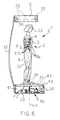
- the toy 1 comprises a base 23 that comprises a body 36 and a supporting upper table 24 on which the toy-figure 2 is positioned.
- the supporting upper table 24 In the supporting upper table 24 are defined two portions 25 capable of supporting the toy-figure 2 at the points of support of its structure, namely the feet of the doll, when the latter is positioned erect on the base 23 (Fig. 1).
- the two portions 25 of the supporting upper table 24 are made of a metallic ferromagnetic material, while the rest of the surface is made of an electrically insulating material such as plastic.
- a canopy 31 is supported above the base 23 by two upright rods 32.
- the toy-figure 2 is thus inserted between the base 23 and the canopy 31.
- the distance from the canopy 31 to the supporting table 24 is such that the top 33 of the toy-figure 2, that is the head of the doll, is positioned close to the canopy 31 without interfering with it.
- Magnets marked 34 and 35 are advantageously housed in the top 33 of the toy-figure 2 and in the canopy 31, respectively. These magnets are able to generate a magnetic force of attraction between the top 33 of the toy-figure 2 and the canopy 31 so as to further increase the stability of the toy-figure 2 on the supporting table 24 during the articulation of the joint 5.
- the magnets 35 housed inside the canopy 31 are preferably positioned in a ring so as to circumscribe the magnet 34 contained inside the top 33 of the toy-figure 2.
- the toy 1 comprises means 27 for limiting the rotation of the upper supporting table 24 with respect to the body 36 of the base 23.
- these means take the form of a magnet 27 housed inside the base 23 and integral with the body 36 of the latter.
- the magnet 27 is positioned in such a way as to be situated along the circular path described by the portions 25 of the upper supporting table 24 during the rotation of the table and in such a way that its pole of opposite sign to that directed downwards by the magnets 26 is turned towards the supporting upper table 24.
- the toy 1 further comprises means 28 for detecting a sound signal and command and control means 29 able to generate a supply signal with which to supply the abovementioned electrically activated motor means 8 as a function of the detected sound signal.
- the output of the command and control means 29 is electrically connected by electric wires 30 to the abovementioned metallic portions 25 of the supporting upper table 24.
- the supply signal generated in the command and control means 29 therefore travels to the two metallic portions 25. From here, through the electrical contacts 21 positioned in the points of support of the structure of the toy-figure 2 and the electrical wires 22, the abovementioned supply signal is transmitted to the motor means 8 which are thus made to rotate.
- the abovementioned means for detecting a sound signal take the form of a microphone 28, the electrical signal from which is sent to the command and control means 29 after first being suitably amplified.
- the command and control means 29 comprise:
- a low-pass filter is preferably connected so that only the low frequencies of the detected sound signal are used when effecting the comparison with the predetermined threshold value.
- the microphone 28 and the command and control means 29 may advantageously be housed inside the base 23.
- the supply to the command and control means 29 may either come from a battery or via connection to mains electricity.
- the toy-figure 2 When the toy 1 is operating, the toy-figure 2 is stood on the supporting table 24 of the base 23 in such a way that the magnets 26 positioned at the points of support of the structure of the toy-figure 2 cling to the portions 25. This also ensures electrical contact between the abovementioned portions 25 and the electrical contacts 21 of the toy-figure.
- the command and control means 29 As soon as power is supplied to the command and control means 29, for example from an ordinary battery, they generate a supply signal which causes the motor means 8 housed in the upper part 3 of the toy-figure 2, and hence the output shaft 12, to rotate. This activates the articulating means 9, for example the cam 10, which, for the reasons described earlier, results in the articulation of the upper part 3 of the toy-figure 2 with respect to the lower part 4 at the joint 5. In effect, the toy-figure 2 turns about the central point, that is to say about the waistline of the doll.
- the microphone When a sound source, such as a radio or tape player in the on condition is placed in the immediate vicinity of the microphone 28, the microphone generates an electrical signal proportional to the sound strength of the signal detected. This signal is filtered in the low-pass filter so that only the low frequencies of the detected sound signal are sent to the command and control means 29. According to the strength of the detected sound signal, the command and control means 29 proceed in the earlier manner described to reverse the supply signal sent to the motor means 8 in such a way as to bring about an inversion of the direction of rotation of the motor means. In essence, the direction with which the toy-figure 2 is rotating about the joint 5 of the central point is reversed.
- the effect produced is to see the toy-figure moving gracefully in time with the music as if it were dancing. It should be emphasised that the movements of the toy-figure 2 vary with the music picked up by the microphone 28 and are therefore not repetitive. Briefly, the toy-figure 2 executes rotations at a faster or slower speed in response to the music or sounds detected.
- toy-figure 2 can be used as an ordinary toy-figure and played with in other ways.
- the number 40 is a general reference for a base for the toy 1, which differs from the previously described base 23.
- the parts of base 40, which are structurally and functionally identical to the corresponding parts of base 23, are identified by the same reference numerals and are not described below.
- the base 40 comprises a body 41 and a supporting upper table 42 on which the toy-figure 2 is positioned.
- the supporting upper table 42 In the supporting upper table 42 are defined two portions 25 capable of supporting the toy-figure 2 at the points of support of its structure, namely the feet of the doll, when the latter is positioned erect on the base 40.
- the two portions 25 of the supporting upper table 42 are made of a metallic ferromagnetic material, while the rest of the surface is made of an electrically insulating material such as plastic.
- each of the points of support of the toy-figure 2 comprises a magnet 26 so that a magnetic force of attraction is set up between the abovementioned points of support of the structure of the toy-figure 2 and the portions 25 of the supporting upper table 42, thereby keeping the toy-figure steady in its vertical position on the base 40.
- the supporting upper table 42 is supported rotatably by the base 40, in order to rotate with respect to the body 41 about an axis of vertical rotation Y-Y, which coincides with the axis Y-Y of the toy-figure 2.
- the base 40 comprises motor means 43 to rotate the upper supporting table 42 with respect to the body 41 of the base 40.
- said motor means 43 are activated by the same supply signal generated by the command and control means 29.
- the signal generated by the control means 29 causes the activation of the motor means 43 housed in the base 40, and hence of the supporting upper table 42.
- said motor means 43 can be activated by a different supply signal generated by the command and control means 29 or by a signal generated by different command and control means.
- magnetic means are connected to the supporting upper table in correspondence of the portions capable of supporting the toy-figure and the points of support of the structure of the toy-figure comprises portion of metallic ferromagnetic material.
- the ball joint can be replaced with some other functionally equivalent type of joint capable of allowing articulation of the upper part of the toy-figure with respect to the lower part.
- the means for articulating together the upper and lower parts of the toy-figure can be replaced with a functionally equivalent cam and cam-follower assembly, not excluding a positive-drive cam system.
- the means for detecting a sound signal, and the command and control means can be housed inside the structure of the toy-figure.
- the toy-figure may also comprise more than one point of articulation so as to obtain different effects.
- the head of the doll may be articulated with respect to the bust, using the same output shaft of the motor/gearbox unit or by a mechanical motion drive.
- the means for articulating together the two parts of the toy-figure may comprise a solenoid integral with one part of the joint and a movable core of ferromagnetic material fitted inside the solenoid and connected to the remaining part of the joint.
- This version presents the advantage of small size and consequently is advantageous for articulating parts of the toy-figure where space is very limited, such as for example the neck and arms of a doll.
Landscapes
- Toys (AREA)
Applications Claiming Priority (2)
| Application Number | Priority Date | Filing Date | Title |
|---|---|---|---|
| PCT/IB1999/000379 WO2000051698A1 (en) | 1999-03-04 | 1999-03-04 | Toy comprising a self-moving toy-figure |
| WOPCT/IB99/00379 | 1999-03-04 |
Publications (2)
| Publication Number | Publication Date |
|---|---|
| EP1033159A2 true EP1033159A2 (de) | 2000-09-06 |
| EP1033159A3 EP1033159A3 (de) | 2000-11-29 |
Family
ID=11004827
Family Applications (1)
| Application Number | Title | Priority Date | Filing Date |
|---|---|---|---|
| EP00200778A Withdrawn EP1033159A3 (de) | 1999-03-04 | 2000-03-03 | Spielzeug mit einer selbstbewegenden Spielzeugfigur |
Country Status (3)
| Country | Link |
|---|---|
| EP (1) | EP1033159A3 (de) |
| AU (1) | AU2541299A (de) |
| WO (1) | WO2000051698A1 (de) |
Cited By (4)
| Publication number | Priority date | Publication date | Assignee | Title |
|---|---|---|---|---|
| EP1530991A1 (de) * | 2003-11-11 | 2005-05-18 | Evolve NPD Limited | Magnetisches Spielzeug |
| EP2085129A1 (de) * | 2008-01-31 | 2009-08-05 | Bandai Co., Ltd. | Marionettenspielzeug |
| USD838323S1 (en) | 2017-07-21 | 2019-01-15 | Mattel, Inc. | Audiovisual device |
| US10866784B2 (en) | 2017-12-12 | 2020-12-15 | Mattel, Inc. | Audiovisual devices |
Families Citing this family (2)
| Publication number | Priority date | Publication date | Assignee | Title |
|---|---|---|---|---|
| US10105613B1 (en) | 2017-12-01 | 2018-10-23 | Spin Master Ltd. | Connectable toy figurines |
| CN115671753A (zh) * | 2021-07-26 | 2023-02-03 | 曾迪 | 用于充气玩具的驱动装置和带有驱动装置的充气玩具系统 |
Family Cites Families (6)
| Publication number | Priority date | Publication date | Assignee | Title |
|---|---|---|---|---|
| GB2154890B (en) * | 1984-09-17 | 1986-09-10 | Douglas Soon Taek Kim | Dancing hula doll |
| JPH0353293U (de) * | 1989-09-25 | 1991-05-23 | ||
| JPH0582492U (ja) * | 1992-04-10 | 1993-11-09 | 株式会社タカラ | 磁気玩具 |
| US5518784A (en) * | 1994-09-23 | 1996-05-21 | Fussell; David A. | Animated decorative ornament |
| US5846115A (en) * | 1995-12-22 | 1998-12-08 | Feng; Pan-Chang Pao | Animated stuffed toy |
| FR2747587A1 (fr) * | 1996-04-22 | 1997-10-24 | Belat Alain | Dispositif permettant de faire danser automatiquement une poupee au rythme de la musique environnante |
-
1999
- 1999-03-04 AU AU25412/99A patent/AU2541299A/en not_active Abandoned
- 1999-03-04 WO PCT/IB1999/000379 patent/WO2000051698A1/en not_active Ceased
-
2000
- 2000-03-03 EP EP00200778A patent/EP1033159A3/de not_active Withdrawn
Non-Patent Citations (1)
| Title |
|---|
| None |
Cited By (5)
| Publication number | Priority date | Publication date | Assignee | Title |
|---|---|---|---|---|
| EP1530991A1 (de) * | 2003-11-11 | 2005-05-18 | Evolve NPD Limited | Magnetisches Spielzeug |
| US7297042B2 (en) | 2003-11-11 | 2007-11-20 | Evolve Npd Limited | Magnetic toy |
| EP2085129A1 (de) * | 2008-01-31 | 2009-08-05 | Bandai Co., Ltd. | Marionettenspielzeug |
| USD838323S1 (en) | 2017-07-21 | 2019-01-15 | Mattel, Inc. | Audiovisual device |
| US10866784B2 (en) | 2017-12-12 | 2020-12-15 | Mattel, Inc. | Audiovisual devices |
Also Published As
| Publication number | Publication date |
|---|---|
| WO2000051698A1 (en) | 2000-09-08 |
| EP1033159A3 (de) | 2000-11-29 |
| AU2541299A (en) | 2000-09-21 |
Similar Documents
| Publication | Publication Date | Title |
|---|---|---|
| US7815485B2 (en) | Pose and play dolls | |
| US6322420B1 (en) | Plush toy having ear and foot movement | |
| US3722134A (en) | Self-propelled continuously moving toy | |
| US3783550A (en) | Novelty electric motor | |
| US7338341B2 (en) | Dancing toy | |
| WO2000051698A1 (en) | Toy comprising a self-moving toy-figure | |
| US6935919B2 (en) | Animation device for head, mouth, arms and body of a toy | |
| US5518784A (en) | Animated decorative ornament | |
| US5181877A (en) | Apparatus for simulating a licking motion | |
| JPH0768055A (ja) | 生き物を模した人形等の玩具 | |
| JP3650780B2 (ja) | 人形玩具 | |
| US10369488B1 (en) | Magnetic spinning toy | |
| JPH084661B2 (ja) | ステージ玩具装置 | |
| US6261148B1 (en) | Twisting animated figure | |
| US6604981B1 (en) | Animated toy animal | |
| US10105613B1 (en) | Connectable toy figurines | |
| CN205948383U (zh) | 一种电动玩具花及玩具盆花 | |
| JPH02268789A (ja) | 磁力利用アクション玩具 | |
| JPH042711Y2 (de) | ||
| JP2507705Y2 (ja) | 人形玩具 | |
| CN214319108U (zh) | 一种娱乐装置 | |
| US3100949A (en) | Animated figure toy | |
| GB2119264A (en) | Animated doll, with rocking support | |
| JPH0349751Y2 (de) | ||
| CN219701059U (zh) | 一种电动跳舞玩偶 |
Legal Events
| Date | Code | Title | Description |
|---|---|---|---|
| PUAI | Public reference made under article 153(3) epc to a published international application that has entered the european phase |
Free format text: ORIGINAL CODE: 0009012 |
|
| AK | Designated contracting states |
Kind code of ref document: A2 Designated state(s): AT BE CH CY DE DK ES FI FR GB GR IE IT LI LU MC NL PT SE |
|
| AX | Request for extension of the european patent |
Free format text: AL;LT;LV;MK;RO;SI |
|
| PUAL | Search report despatched |
Free format text: ORIGINAL CODE: 0009013 |
|
| AK | Designated contracting states |
Kind code of ref document: A3 Designated state(s): AT BE CH CY DE DK ES FI FR GB GR IE IT LI LU MC NL PT SE |
|
| AX | Request for extension of the european patent |
Free format text: AL;LT;LV;MK;RO;SI |
|
| AKX | Designation fees paid | ||
| REG | Reference to a national code |
Ref country code: DE Ref legal event code: 8566 |
|
| STAA | Information on the status of an ep patent application or granted ep patent |
Free format text: STATUS: THE APPLICATION IS DEEMED TO BE WITHDRAWN |
|
| 18D | Application deemed to be withdrawn |
Effective date: 20010530 |