EP1033205A2 - Werkzeug zum Ein- und Ausbau von Ventilkernen - Google Patents
Werkzeug zum Ein- und Ausbau von Ventilkernen Download PDFInfo
- Publication number
- EP1033205A2 EP1033205A2 EP00301317A EP00301317A EP1033205A2 EP 1033205 A2 EP1033205 A2 EP 1033205A2 EP 00301317 A EP00301317 A EP 00301317A EP 00301317 A EP00301317 A EP 00301317A EP 1033205 A2 EP1033205 A2 EP 1033205A2
- Authority
- EP
- European Patent Office
- Prior art keywords
- tool
- valve core
- head portion
- valve
- bore
- Prior art date
- Legal status (The legal status is an assumption and is not a legal conclusion. Google has not performed a legal analysis and makes no representation as to the accuracy of the status listed.)
- Withdrawn
Links
Images


Classifications
-
- B—PERFORMING OPERATIONS; TRANSPORTING
- B25—HAND TOOLS; PORTABLE POWER-DRIVEN TOOLS; MANIPULATORS
- B25B—TOOLS OR BENCH DEVICES NOT OTHERWISE PROVIDED FOR, FOR FASTENING, CONNECTING, DISENGAGING, OR HOLDING
- B25B27/00—Hand tools, specially adapted for fitting together or separating parts or objects whether or not involving some deformation, not otherwise provided for
- B25B27/14—Hand tools, specially adapted for fitting together or separating parts or objects whether or not involving some deformation, not otherwise provided for for assembling objects other than by press fit or detaching same
- B25B27/24—Hand tools, specially adapted for fitting together or separating parts or objects whether or not involving some deformation, not otherwise provided for for assembling objects other than by press fit or detaching same mounting or demounting valves
-
- B—PERFORMING OPERATIONS; TRANSPORTING
- B25—HAND TOOLS; PORTABLE POWER-DRIVEN TOOLS; MANIPULATORS
- B25B—TOOLS OR BENCH DEVICES NOT OTHERWISE PROVIDED FOR, FOR FASTENING, CONNECTING, DISENGAGING, OR HOLDING
- B25B13/00—Spanners; Wrenches
- B25B13/48—Spanners; Wrenches for special purposes
Definitions
- the present invention relates to a tire valve (core) mounting and dismounting tool and, more particularly, to an improved tyre valve (core) mounting and dismounting tool that is capable of removing from, and attaching to, a valve casing a valve body portion, commonly called a "valve core", with easiness and with reliability, and yet with a single hand, for a tire air valve, regardless of types of vehicle tires in which such tire air valves may have been mounted.
- core tire valve
- core tyre valve
- a tire air valve is mounted or installed into a tire for every vehicle, e. g., bicycles, motor cycles and automobiles including a commercial vehicle or truck, a motor bus and a passenger car.
- a valve commonly includes a casing in the form of a tubular or hollow cylindrical body that is a portion secured into a tire, and a valve "core" or body portion which when received in place in the tubular casing provides a conventional air valve mechanism and its pressure air inlet and closure functions.
- the valve core is typically provided with an air inlet passage formed in a space between a tubular part with both ends open and a shaft passing through the tubular part coaxially therewith.
- the shaft has a flange secured thereto and is spring biased in the tubular part so that the flange normally closes one end (on the side proximal to the tire interior) air tight.
- the tubular part is associated with a head portion, called a "valve core head" portion, at the side distal to the tire interior, through which air is led from a pneumatic pump.
- the valve core shaft portion past the tubular part extends through and protrudes from the head portion and has a round and somewhat enlarged end face at its top or foremost end.
- the tubular valve casing is formed with a threaded inner surface and the valve core is provided with a threaded outer surface typically on the valve core head portion so that these two surfaces may be in mesh or interlocked with each other. Therefore, tire air valves for vehicle tires, regardless of types of the tyres in which they are loaded, commonly have a design such that screwing the valve core into the tubular casing may assemble the valve, i. e., make the valve core assume its operative position, and unscrewing the valve core from the tubular valve casing may disassemble the valve, i. e., may detach the valve core from the casing. With the valve assembled, the entire valve core including the head portion and the portion of the shaft that protrudes from the head portion must be accommodated within the tubular casing in order to protect it from any damaging external force.
- tires for automobiles entail a specified air pressure that is considerably elevated.
- air blows intensively from the tire air valve even for a moment, making it difficult even to keep the valve core retained on the tool. Rather, it has often be the case that a valve core comes to be blown off by the high pressure air blow from the valve, and eventually be lost.
- Such incidences are especially salient with tire air valves in the tires on automobiles such as commercial vehicles or motor buses in which the air pressure is even more increased.
- the present invention is directed to a tire valve (core) mounting and dismounting tool for a tire air valve having a tubular casing mounted in a vehicle tire and a valve core which is screwed into the tubular casing to form the tire air valve and is unscrewed for removal from the tubular body and to dismount the tire air valve, the valve core having a valve core head portion and a valve core shaft portion that extends through and protrudes from the valve core head portion and has a round enlarged shaft end.
- An improved tire air valve (core) comprises a tool head portion, a tool shank portion, and a tool grip portion.
- the said tool head portion is formed at its top or foremost end with a slot for seizing and holding the valve core head portion in a snug fit.
- the said tool head portion also has:
- the elasticity of the said spring means is also such as to force the enlarged round end of the said valve core shaft portion to move deeper in the said axial bore beyond the said ball means and then to allow the said ball means to restore its biased state as set forth and thereby to act to hold the said enlarged shaft end against moving back.
- the said second bore may comprise a plurality of second bores and the said ball means may then comprise a plurality of substantially spherical balls which is accepted in the said second bores, respectively.
- the said spring means comprises a spring in the form of a character C.
- the said spring means comprises a coil spring having a plurality of turns with a number of turns selected from two to four.
- the said second bore comprises a pair of second bores disposed substantially diametrically opposite to each other about a longitudinal axis of the said tool head portion, and the said ball means then comprises a pair of spherical balls which are accepted in the two second bores, respectively.
- a tyre valve (core) mounting and dismounting tool when constructed as described above enables a valve core to be mounted into and dismounted from its tubular casing mounted in a vehicle tire, easily and reliably, and even with a single hand.
- the tool has also been found to be operable easily and reliably in a screwing and an unscrewing operation for a tyre air valve while enduring or withstanding to a high pressure air blow from the tyre in which the valve is mounted.
- the tool has also been found to be usable with air valves with casings mounted even in tires of such vehicles as commercial vehicles and motor busses.
- a tire air valve that is installed into a tire for every vehicle, e. g., bicycles, motor cycles and automobiles including a commercial vehicle or truck, a motor bus and a passenger car.
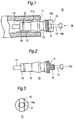
- a valve denoted by general reference 10 commonly includes a casing 11 in the form of a tubular or hollow cylindrical body that is a portion secured into a tire (not shown), and a valve core or body portion 12 which when received in place in the tubular casing 11 provides a conventional air valve mechanism and its pressure air inlet and closure functions.
- the valve core 12 is typically provided with an air inlet passage P formed in a space between a tubular part 13 with both ends open and a shaft 14 that passes through the tubular part 13 coaxially therewith.
- the shaft 14 has a flange 15 secured thereto and is spring biased in the tubular part 13 so that the flange 15 normally closes one end (on the side proximal to the tire interior) air tight.
- the tubular part 13 is associated with a head portion 16, called a "valve core head" portion, at the side distal to the tire interior, through which air is led from a pneumatic pump (not shown).
- the valve core shaft portion 14 past the tubular part 13 extends through and protrudes from the head portion 12 and has a round and somewhat enlarged end surface 14a at its top.
- the shaft 14 is pushed with a force applied onto that round enlarged end surface 14a, the shaft 14 is moved against the spring bias relative to the tubular part 13 that is fixed in position to the valve tubular casing 11 to provide an opening as indicated by the arrow O between the closing flange and the tubular part, thus to establish fluid communication of the air inlet passage P with the tire or tire tube interior.
- the tubular valve casing 11 is formed with a threaded inner surface 11a and the valve core 12 is provided with a threaded outer surface 12a typically on the valve core head portion 16 so that these two surfaces 11a and 12 may come into and out of mesh with each other.
- tire air valves 10 for vehicle tires commonly have a design such that screwing the valve core 12 into the tubular casing 11 may assemble the valve 10, i. e., make the valve core 12 assume its operative position, and unscrewing the valve core 12 from the tubular valve casing 11 may disassemble the valve 10, i. e., may detach the valve core 12 from the casing 11.
- the entire valve core 12 including the head portion 16 and the portion of the shaft 14 that protrudes from the head portion 16 must be accommodated within the tubular casing 11 in order to protect it from any damaging external force.
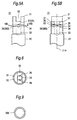
- Figs. 4A and 4B depict an appearance of an improved tire valve (core) mounting and dismounting tool as indicated by general reference numeral 20, which is designed to be applicable to a tire valve core 10 as described above.
- the tool 20 is shown to include a tool head portion 21, a tool shank portion 22, and a tool grip portion 23. These separate portions 21, 22 and 23 are secured together and coaxially with each other. It can be seen that the tool 20 resembles a conventional screw driver except for a unique construction and configuration, as described below in detail, of the tool head portion 21 provided at the top end of the shaft portion 22 held by the grip portion 23.
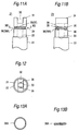
- Figs. 5A and 5B through 10A and 10B show a first form of embodiment of the tool head portion 21 whereas Figs. 11A and 11B through 14A and 14B show an alternative but preferred form of the tool head portion 21 of a tire valve (core) mounting and dismounting tool 20 according to the present invention.
- Figs. 7 and 8 are common to the latter form of embodiment as well.
- the tool head portion 21 is generally cylindrical with its periphery being round and is formed at its top or forward end 31 with a slot 32 that is adapted to seize and hold, in a snug fit, a valve core head portion 16 as previously described.
- the tool head portion 21 in these embodiments also has a cylindrical axial bore 33 formed coaxially of the tool head portion 21.
- the axial bore 33 has its inner wall smooth and is adapted to receive the said valve core shaft portion 14 and to accept the round enlarged shaft end 14a thereof in a snug fit.
- the axial bore 33 extends to and is thus open to the valve core head seizing and holding slot 32.
- the slot 32 is formed by cutting and the axial bore 33 by drilling.
- the tool head portion 21 also has, below the slot 32 as shown, an annular recess or groove 34 formed along a peripheral surface of the tool head portion 21 so as to encircle the axial bore 33.
- a second bore or bores, a pair of bores 35 as shown are also formed in the tool head portion 21 so as to extend radially outwards thereof and to be open to the said annular groove 34 and spherical balls 36 are slidably received in these bores, respectively.
- the second bores 35 are each individually in communication with the axial bore 33 through an opening 37 that may be circular and are each smaller in diameter than each spherical ball 36.
- the bores 35 are shown to have each a cylindrical wall that commences at a portion of annular groove 34 and which as it approaches the axial bore 33 becomes spherical or is tapered spherically, ending with the circular opening 37 with a somewhat reduced diameter.
- Each of the bores 35 is so configured as to allow the ball 36 to slidably move in the bore 35 in its oriented radial direction, and the opening 37 is so sized not only to prevent the ball 36 from falling into the axial bore 33 but to allow the ball 36 in its innermost position to partially protrude out of the opening 37 into the axial bore 33 as shown diagrammatically in Figs. 6, 7, 8 and 12.
- the annular groove 34 is formed by cutting and the ball reception bores 35 with their respective openings 37 by drilling or boring.
- the two bores 35 are here disposed diametrically opposite to each other about a longitudinal axis 21A of the tool head portion 21.
- the annular groove 34 is adapted to receive a spring 38 that can be a flat spring 38B in the form of character C as shown in Fig. 9 in the first embodiment.
- the spring 38 may alternatively and should more preferably be a coil spring 38A having a plurality of turns as shown in Figs. 13A and 13B as adopted in the second embodiment. The number of turns is then selected from 2 to 4.
- Figs. 5A and 5B and 11A and 11B the spring 38 is shown to have been anchored and fastened in the annular groove 34.
- the spring is so anchored and fastened after the balls 36 are put in their respective reception bores 37.
- the spring 38 acts to resiliently or elastically hold the balls 36 and to normally bias the balls 36 radially inwards of the cylindrical body portion of the tool head 21 to allow the balls 36 to be kept partially and somewhat protruding out of the respective ball retaining bores 35 into the axial bore 34 through the small opening 37.
- a tyre valve core 12 is shown as being detached by the operator from its tubular casing 11 not shown but shown in Fig. 1.
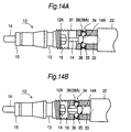
- Figs. 10A and 14A show in an enlarged cross section a state before the valve core 12 is not completely caught and accepted by the tool head portion 31.
- Figs. 10B and 14B show in an enlarged cross section a state after the valve core 12 is caught and held by the tool head portion 31.
- valve core head 16 lies slightly entering the seizing and holding slot 32 (Figs. 5A and 11A) formed at the top or foremost end 31 of the tool head portion 31, and the enlarged round end 14a of the valve core shaft 14 lies somewhat entering the insertion inlet of the shaft accepting axial bore 33 and in contact with the balls 36 partially protruding from their respective ball accepting bores 35 through the respective openings 37 as mentioned before.
- the operator may hold the tool 20 (Figs. 4A and 4B) by holding its shank portion 22 between two fingers of his/her one hand and holding its grip portion 23 with these fingers and the thumb of the same hand, and may then engage the tool 20 so as to allow the valve core shaft and head portions 14 and 16 to move into the slot 32 and the enlarged round shaft end 14a to enter the axial bore 33.
- the enlarged round shaft end 14a is felt to hit the balls 36, the state shown in Figs. 10A and 14A will have been reached.
- the spring means 38 is here designed to possess an elasticity that is adequate to permit the balls 36 that has partially come out of the bores 35, when they are pushed by the moving shaft end portion 14a, to be pushed thereby to move in the ball accepting bores 35 and completely out of the axial bore 33, and yet to be retained in the bores 35 by the spring means 38.
- valve core 12 With its head portion held in the slot 32 of the tool head portion 21 also to turn, thus permitting the valve core 12 to be unscrewed and detached from the valve tubular casing 11 (Fig. 1) for replacement with a new valve core or mounting again.
- the valve core may then be detached from the tool 20 simply by applying a light pull between them.
- valve core or a new valve core 12 may be mounted first by holding it with the other hand and holding the tool 20 as mentioned before. This time, the valve core 12 is engaged with the tool 20, and a thrust or push as mentioned before may be applied from the valve core 12 side to permit the valve core head portion 16 to be held by the slot 32 and the valve core shaft portion 14 and its enlarged end 14 to be caught in the axial bore 33 by the balls. Then, turning clockwise the tool 20 with its grip portion will allow the valve core 12 to be screwed with the tubular casing 11 within it.
- the operator may simply pull the tool 20 towards the operator to detach the tool head portion 21 and remove the tool 20 from the valve core 12 set in the valve.
- valve core 12 both when a valve core 12 is removed from its tubular casing 11 in the tire and when a valve core 12 is mounted into the valve casing 11, the construction that allows both the valve core head head portion 12 and the valve core shaft portion 14 to be seized and held reliably prevents the valve core 12 from being blown away from the valve mounting and detaching tool 20 by a high pressure air flow momentarily flushed through the valve 10 from the tire, yet permitting both a mounting and a detachment operation to be performed easily and reliably with a single hand.
- a coil spring 38A as shown in Figs. 13A and 13B and described before is preferred to a flat C-shaped spring as shown in Figs. 6 and 9 because of highly superior durability to an increased air pressure burst and hence is much more desirable for tire air valves for automobiles such as commercial vehicles, motor buses, etc.
- the tool shank portion 22, the valve core head portion 21, the balls 36 and the coil means 38 which make up the valve mounting and dismounting tool 20 are preferably made of a stainless alloy steel, but they may be made of any other suitable material or materials.
- the shank portion 22 and the grip portion 23 may have optional lengths that can be selected to meet with particular type of tire or tires in which an applicable tire valve or valves are installed. They may also have optional sizes and machined dimensions without particular limitation that can be selected to meet with an applicable valve core or cores.
- valve core mounting and dismounting tool for dismounting and mounting a valve core that has been or is being screwed with a tire valve tubular casing mounted in the tire will, regardless of the type of a particular tire in which it is installed, allow the valve core to be seized and held by the valve core mounting and dismounting tool with a single hand, and with ease and with reliability even with one hand. Without the inconvenience that a valve core may come off from the tool and may then drop by gravity, its workability is drastically enhanced.
Landscapes
- Engineering & Computer Science (AREA)
- Mechanical Engineering (AREA)
- Check Valves (AREA)
- Hand Tools For Fitting Together And Separating, Or Other Hand Tools (AREA)
Applications Claiming Priority (2)
| Application Number | Priority Date | Filing Date | Title |
|---|---|---|---|
| JP11089537A JP2000237972A (ja) | 1999-02-22 | 1999-02-22 | バルブコア着脱工具 |
| JP8953799 | 1999-02-22 |
Publications (2)
| Publication Number | Publication Date |
|---|---|
| EP1033205A2 true EP1033205A2 (de) | 2000-09-06 |
| EP1033205A3 EP1033205A3 (de) | 2003-04-16 |
Family
ID=13973576
Family Applications (1)
| Application Number | Title | Priority Date | Filing Date |
|---|---|---|---|
| EP00301317A Withdrawn EP1033205A3 (de) | 1999-02-22 | 2000-02-21 | Werkzeug zum Ein- und Ausbau von Ventilkernen |
Country Status (3)
| Country | Link |
|---|---|
| EP (1) | EP1033205A3 (de) |
| JP (1) | JP2000237972A (de) |
| CA (1) | CA2299014A1 (de) |
Cited By (4)
| Publication number | Priority date | Publication date | Assignee | Title |
|---|---|---|---|---|
| DE102008059612A1 (de) | 2008-11-28 | 2010-06-02 | Audi Ag | Handbetätigtes stabförmiges Werkzeug |
| CN103406875A (zh) * | 2013-08-14 | 2013-11-27 | 南京南化建设有限公司 | 一种对拉螺栓预留垫圈拆卸装置 |
| ES2475415A1 (es) * | 2013-01-08 | 2014-07-10 | Jes�s Mar�a MART�NEZ CAMPOS | útil para el montaje/desmontaje del obús de la válvula de neumáticos |
| CN106112914A (zh) * | 2016-08-24 | 2016-11-16 | 中国水利水电第十三工程局有限公司 | 一种逆止阀阀芯更换工具及更换方法 |
Families Citing this family (6)
| Publication number | Priority date | Publication date | Assignee | Title |
|---|---|---|---|---|
| KR102028306B1 (ko) * | 2019-06-21 | 2019-10-02 | 송정규 | 타이어 밸브코어 탈착용 전동공구 |
| TWI765212B (zh) * | 2020-01-10 | 2022-05-21 | 奕道實業有限公司 | 氣閥拆裝組件 |
| CN111941347A (zh) * | 2020-07-14 | 2020-11-17 | 东风汽车集团有限公司 | 车辆传动轴拆卸装置 |
| CN113601458B (zh) * | 2021-08-09 | 2022-09-20 | 凯喜姆阀门有限公司 | 一种固定球阀阀座的安装方法以及拆卸方法 |
| CN116906614B (zh) * | 2023-09-13 | 2023-11-21 | 成都成高阀门股份有限公司 | 一种低温球阀阀座防转装置及其使用方法 |
| CN117340832A (zh) * | 2023-10-27 | 2024-01-05 | 华能澜沧江水电股份有限公司 | 用于接地开关的静触头拆除工具 |
Family Cites Families (8)
| Publication number | Priority date | Publication date | Assignee | Title |
|---|---|---|---|---|
| US3852839A (en) * | 1972-08-09 | 1974-12-10 | Blt Ind | Tire tool |
| US4453449A (en) * | 1981-09-10 | 1984-06-12 | Westinghouse Electric Corp. | Holding apparatus |
| US4645372A (en) * | 1984-10-01 | 1987-02-24 | Matsui-Walterschield Ltd. | Power transmitting coupling |
| SE501892C2 (sv) * | 1993-10-15 | 1995-06-12 | Drester Ab | Verktyg för avlägsning av en luftventilinsats hos ett fordonsdäck |
| US5533429A (en) * | 1994-11-30 | 1996-07-09 | Kozak; Burton | Fastener driving tool insert |
| DE29601149U1 (de) * | 1996-01-24 | 1996-03-07 | Chang, Jui-Feng, Tai Ping Hsiang, Taichung | Verlängerung für ein Handwerkzeug |
| JPH09315114A (ja) * | 1996-05-27 | 1997-12-09 | Aruma Trading Kk | バルブコア着脱工具 |
| DE19629352A1 (de) * | 1996-07-20 | 1998-01-22 | Anton Gaupp | Adaptervorrichtung für eine Ratsche |
-
1999
- 1999-02-22 JP JP11089537A patent/JP2000237972A/ja active Pending
-
2000
- 2000-02-17 CA CA 2299014 patent/CA2299014A1/en not_active Abandoned
- 2000-02-21 EP EP00301317A patent/EP1033205A3/de not_active Withdrawn
Cited By (4)
| Publication number | Priority date | Publication date | Assignee | Title |
|---|---|---|---|---|
| DE102008059612A1 (de) | 2008-11-28 | 2010-06-02 | Audi Ag | Handbetätigtes stabförmiges Werkzeug |
| ES2475415A1 (es) * | 2013-01-08 | 2014-07-10 | Jes�s Mar�a MART�NEZ CAMPOS | útil para el montaje/desmontaje del obús de la válvula de neumáticos |
| CN103406875A (zh) * | 2013-08-14 | 2013-11-27 | 南京南化建设有限公司 | 一种对拉螺栓预留垫圈拆卸装置 |
| CN106112914A (zh) * | 2016-08-24 | 2016-11-16 | 中国水利水电第十三工程局有限公司 | 一种逆止阀阀芯更换工具及更换方法 |
Also Published As
| Publication number | Publication date |
|---|---|
| EP1033205A3 (de) | 2003-04-16 |
| CA2299014A1 (en) | 2000-08-22 |
| JP2000237972A (ja) | 2000-09-05 |
Similar Documents
| Publication | Publication Date | Title |
|---|---|---|
| US6152165A (en) | Valve core mounting and dismounting tool | |
| EP1033205A2 (de) | Werkzeug zum Ein- und Ausbau von Ventilkernen | |
| US7086813B1 (en) | Quick-acting tool bit holder | |
| EP2223760B1 (de) | Werkzeugrückhaltevorrichtung | |
| US8800999B2 (en) | Bit retention device | |
| US20180257205A1 (en) | Multipurpose tire tool | |
| US20020020973A1 (en) | Workpiece connector for a power tool | |
| US5551816A (en) | Removable rivet and method of removing the head from the shank of the rivet | |
| US9616719B1 (en) | Valve cap and core tool | |
| US10675739B2 (en) | Multi-function socket | |
| US4718639A (en) | Tire valve bodies | |
| JP2012047686A (ja) | タイヤバルブユニット | |
| US4905547A (en) | Master key for wheel cover lock bolts or nuts | |
| US10549355B1 (en) | Lug nut removal tool | |
| JPH10299817A (ja) | ステイダンパ | |
| CA2673674C (en) | Valve stem puller | |
| US6032510A (en) | Blind rivet setting tool | |
| KR200239767Y1 (ko) | 베어링 착탈기 | |
| US20140109982A1 (en) | Valve stem repair kit and method | |
| JPH10180652A (ja) | 相異なるタイプの複数の空気動工具と共に使用される装置、空気動工具用絞り弁空気入口および空気入口ブッシュ | |
| JPH10252805A (ja) | スティダンパ | |
| US4021903A (en) | Method and tool for removing lock cylinder assemblies | |
| US20230234195A1 (en) | Valve stem insertion device | |
| US20070102889A1 (en) | Tool handle assembly | |
| EP4052934B1 (de) | Ventil für gummierte räder mit betätigungsmechanismus |
Legal Events
| Date | Code | Title | Description |
|---|---|---|---|
| PUAI | Public reference made under article 153(3) epc to a published international application that has entered the european phase |
Free format text: ORIGINAL CODE: 0009012 |
|
| AK | Designated contracting states |
Kind code of ref document: A2 Designated state(s): AT BE CH CY DE DK ES FI FR GB GR IE IT LI LU MC NL PT SE |
|
| AX | Request for extension of the european patent |
Free format text: AL;LT;LV;MK;RO;SI |
|
| PUAL | Search report despatched |
Free format text: ORIGINAL CODE: 0009013 |
|
| AK | Designated contracting states |
Designated state(s): AT BE CH CY DE DK ES FI FR GB GR IE IT LI LU MC NL PT SE |
|
| AX | Request for extension of the european patent |
Extension state: AL LT LV MK RO SI |
|
| RIC1 | Information provided on ipc code assigned before grant |
Ipc: 7B 60C 25/18 A |
|
| 17P | Request for examination filed |
Effective date: 20031009 |
|
| AKX | Designation fees paid |
Designated state(s): DE ES FR GB IT |
|
| STAA | Information on the status of an ep patent application or granted ep patent |
Free format text: STATUS: THE APPLICATION IS DEEMED TO BE WITHDRAWN |
|
| 18D | Application deemed to be withdrawn |
Effective date: 20040302 |