EP1033342A2 - Greifer zum Heben und Transportieren von Metalbandrollen - Google Patents
Greifer zum Heben und Transportieren von Metalbandrollen Download PDFInfo
- Publication number
- EP1033342A2 EP1033342A2 EP00660042A EP00660042A EP1033342A2 EP 1033342 A2 EP1033342 A2 EP 1033342A2 EP 00660042 A EP00660042 A EP 00660042A EP 00660042 A EP00660042 A EP 00660042A EP 1033342 A2 EP1033342 A2 EP 1033342A2
- Authority
- EP
- European Patent Office
- Prior art keywords
- lifting
- lifting arms
- gripping
- lifter
- arms
- Prior art date
- Legal status (The legal status is an assumption and is not a legal conclusion. Google has not performed a legal analysis and makes no representation as to the accuracy of the status listed.)
- Withdrawn
Links
Images

Classifications
-
- B—PERFORMING OPERATIONS; TRANSPORTING
- B66—HOISTING; LIFTING; HAULING
- B66C—CRANES; LOAD-ENGAGING ELEMENTS OR DEVICES FOR CRANES, CAPSTANS, WINCHES, OR TACKLES
- B66C1/00—Load-engaging elements or devices attached to lifting or lowering gear of cranes or adapted for connection therewith for transmitting lifting forces to articles or groups of articles
- B66C1/10—Load-engaging elements or devices attached to lifting or lowering gear of cranes or adapted for connection therewith for transmitting lifting forces to articles or groups of articles by mechanical means
- B66C1/22—Rigid members, e.g. L-shaped members, with parts engaging the under surface of the loads; Crane hooks
- B66C1/28—Duplicate, e.g. pivoted, members engaging the loads from two sides
- B66C1/30—Duplicate, e.g. pivoted, members engaging the loads from two sides and also arranged to grip the sides of the loads
Definitions
- the present invention relates to a gripping lifter intended for transferring metal coils as in the preambles to claims 1 and 6.
- the invention also relates to a method as in the preamble to claim 8 for lifting metal coils and a method as in the preamble to claim 10 for transferring metal coils.
- the inner position of a projecting part refers to the position of the projecting part in which it is located, in its entirety, within the lifting arm.
- the outer position refers to the position of the projecting part in which the longitudinal axis of the projecting part forms as great angle as possible relative to the position of the longitudinal axis in the inner position of the projecting part when said projecting part is viewed in the direction of Figure 2.
- a metal coil means in turn coiled metal, where underneath there is possibly a support frame made of metal.
- a variety of lifters for lifting metal coils are known in the art.
- One type of lifters is provided with a hook at the end of the lifting arm, which is taken into the centre hole of the coil to be lifted by means of pendulous motion. Because of the poor controllability of the pendulous motion of the hook, said lifting arm is poor in job safety, neither is it, because of the width of the lateral motion of the hook, otherwise appropriate for use in crammed storage rooms or locations in which metal coils have to be placed close to one another.
- a slightly more sophisticated lifting device model is known from the EP application No. 971 022.
- the lifting device is provided with two L-shaped lifting arms, being at the upper ends fixed to the support arms in horizontal plane.
- the lower ends of the lifting arms are provided with detecting elements, with the aid of which the centre holes can be located.
- the L-heads of the lifting arms can be inserted into the centre holes by adjusting the distance of the support arms.
- a lifting device such as this is provided with fixed L-shaped lifting heads, whereby the gripping of the lifting device is relatively large owing to the fact that the L-shaped heads of the lifter cannot be brought very close to the metal coil before the centre hole has been detected. Said point limits greatly the use of lifters because coils cannot be picked with the lifter from among the coils packaged very close to each other without causing damage to the coils.
- the width of the gripping motion required by the lifting device also takes a lot of the valuable storage space when packaging metal coils in the storage.
- a problem related to the lifter is also job safety because dangerous situations may arise because of the projecting parts of the lifting arms of the lifting device when moving the lifting arms in tightly packed storage rooms in up-and-down directions.
- lifting devices are known from the art in which the projecting parts on the ends of the lifting arms can be pulled or turned into the lifting arms.
- said lifting devices are intended, without a single exception, primarily for transferring cable coils or equivalent light-weight coils, in which the coil material is not readily damaged, neither will the weight of the coils cause structural problems for the lifting device.
- the projecting parts of the lifting devices intended for lifting a metal coil are required to be sturdy in structure and the lifting device are to be provided with sufficient security equipment wherewith it is ensured that the valuable coil material is not scratched during transfer. If lifting device designs provided with turning projecting parts of the lifting arms are used, the turning mechanism of the projecting part must be firm and long-lasting.
- Metal coils have to be moved from one place to another so that they cannot move on the projecting parts when being transferred.
- the requirements to be met by the lifting device are increased: the lifting device is required to be able to keep the metal coils firmly in place during the lifting operation and it is required to be provided with security means wherewith it is possible to ensure that the transfer of a metal coil is not started before the metal coil is steadily located on the projecting parts. It must also be possible to interrupt a transfer operation if the load moves on the projecting parts during the transfer, not to cause damage to the metal coils.
- a lifting device intended for transferring coils in which the lower ends of the lifting arms are provided with projecting parts turnable within the arms.
- the lifting device is primarily intended for lifting cable coils, and so, it is not appropriate for lifting metal coils because the lever structure intended for moving the projecting parts and the motion limiter of the turning motion of the projecting parts are not appropriate for metal coils. Neither is the lifting device provided with efficient security equipment to ensure the position of the coil prior to and during the transfer of coils.
- a lifting device intended for transferring coils, sheet metal boxes, and equivalent goods is known from the German patent application No. DE-4217333.
- the lifting device introduced in said application publication is impractical, complicated in structure and too expensive in practice for use in transferring metal coils.
- the lifting device includes projecting parts to be pulled inwards and located in the lower ends of the lifting arms but it is not provided with security equipment essential regarding the transfer of metal coils, wherewith damages to metal coils can be prevented. Neither are the projecting parts provided with an efficient motion limiter of the turning motion of projecting parts, because of which the lifting device is not appropriate for heavy metal coils.
- the purpose of the metal-coil lifting device design of the invention is to remove the drawbacks found in the state of art.
- a first objective of the invention is to provide a lifting device intended for transferring heavy metal coils, with the aid of which heavy metal coils can be moved (packaged) tightly into a storage room, in order to minimize the storage space, and on the other hand, to pick an individual metal coil from a tightly packed metal coil store without a risk of damaging the metal coil.
- a second aim of the invention is to provide a lifting device intended for moving heavy metal coils, said device being provided with sufficient security equipment for moving a metal coil safely, and without scratching the surface, from one place to another.
- a third aim of the invention is to provide a lifting device being better in job safety than earlier.
- a fourth aim of the invention is to provide a gripping lifter, the structure of which is strong and firm enough in handling heavy metal coils, while as simple as possible in structure.
- the simple structure reduces production costs and improves the competitiveness of the product.
- the new gripping lifter of the invention is characterized in what is presented in claims 1 and 6.
- the method of the invention for lifting metal coils is on the other hand characterized in what is presented in claim 8.
- the method of the invention for transferring metal coils is characterized in what is presented in claim 10.
- advantageous embodiments of the invention are presented.
- the gripping lifter of the invention intended for handling heavy metal coils is provided with two lifting arms, being coupled at the upper ends to one or more support arms substantially in horizontal plane, the lower ends of the lifting arms being provided with centre hole detectors of the coil, and projecting parts.
- On the inner sides of the lifting arms are positioned gravity-operated detecting elements of the sides of the metal coil.
- the projecting parts have been rotatably carried on the lower parts, their under edge forming part of the limiter of the turning motion of the projecting part, and on the upper part thereof being attached a leverage machinery to be used mechanically.
- the projecting parts are advantageously also provided with load detectors.
- the lifting arms of the gripping lifter are descended close to the sides of a metal coil until the detectors of the centre hole detect the centre hole.
- the motion of the lifting arms of the gripping lifter is stopped and the projecting parts rotatably carried in the lower parts are turned to the outer position.
- the lifting arms of the gripping lifter are approached towards each other until the detecting elements detect the outer sides of the metal coil.
- the gripping motion of the lifting arms towards each other is stopped when the inner sides of the lifting arms are clamped with desired force onto the outer sides of the metal coil and thereafter, the metal coil on the projecting parts of the lifting arms is lifted.
- a metal coil hung on the centre hole on the projecting arms of the lifting device is transferred to its storage location by descending it supported by the lifting arms downwards.
- the lifting arms are lowered further until the detector of the centre hole detects the centre hole. Thereafter, the projecting parts are turned into their inner position.
- the operation of the gripping lifter of the invention is based on projecting parts turnable into the arms on the lower ends of the lifting arms, said projecting parts being provided with load detectors and an efficient limiter of the turning motion, which projecting parts are connected to the detectors of metal coils and the centre hole on the lifting arms.
- the projecting parts of the lifting arms are turned at the rotatably carried point of the lower part into the inner position and the outer position. While in the inner position, the projecting parts remain inside the lifting arms. Therewith the advantage is gained that the inner surface of the lifting arms remains smooth so that the lifting arms will not scratch metal coils when picking metal coils packed tightly to each other in a storage room.
- the advantage is achieved that the gripping motion of the lifting arms can be considerably reduced in comparison with lifter designs provided with fixed projections, so that metal coils can be transferred into crammed locations or take out of crammed locations.
- the load detector can be omitted, while in varying storage conditions it is advantageous to fix also a load detector on the projecting part.
- the projecting parts of the lifting arms are also provided with an efficent and structurally long-lasting motion-limiter part to prevent the projecting part from turning too far when being turned into the outer position.
- the motion limiter of the invention the projecting part is able to carry larger loads and turning it into the outer position is considerably more secure than in lifters of the state of art, such as in the patent documents JP-7-125969 and DE-DE-4217333 mentioned in the preceding, in which a lever mechanism and/or the inner side of the lifting arm are used as motion limiter.
- the lifting arms are turned with a mechanical-hydraulic lever mechanism.
- An advantage of the mechanical-hydraulic lever mechanism lies in the adjustability of the turning angel of the projecting parts compared e.g. with the gravity-operated lever mechanism described in the above JP patent document.
- the detectors of the metal coil sides are located on the inner sides of the lifting arms, with the aid of which the gripping motion of the lifting arms can be stopped at appropriate distance from the sides of the metal coil to be lifted.
- the advantage is gained that the space of the lifting arms, while closest to each other, i.e. while clamped against the outer sides of the metal coil, can be adjusted to conform to the coil size.
- the detectors of the coil sides are gravity-operated, wherewith the advantage is gained that they are as simple as possible in structure.
- the support arms of the gripping lifter of the invention can be functionally connected to a variety of metal coil lifting device, such as port cranes, whereby the additional advantage is gained that the same lifting device can be used in most varied conditions.
- the gripping lifter may comprise two or more functionally connected gripping lifters.
- a gripping lifter like this is provided with three functionally connected gripping lifters. With this kind of connected gripping lifter the additional advantage is gained that several metal coils can be transferred in one time from one place to another.
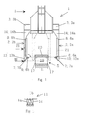
- Figure 1 presents a gripping lifter of the invention when viewed in front view.
- Figure 2 shows a longitudinal section image of the lifting arm as in Figure 1 in front view.
- Figure 3 shows the longitudinal section image III-III of the lifting arm of Figure 1 when viewed from the direction I of Figure 1.
- Figure 4 presents another embodiment of the gripping lifter of the invention in front view.
- the gripping lifter 1 presented in Figure 1 comprises two elongated lifting arms 2a,2b, being slidably fixed on the upper parts 14a,14b onto support arms 3a,3b substantially in horizontal plane.
- the lower ends 13a,13b of the lifting arms are provided with detectors 4A and 4B of the centre hole 19 of the coil 5, and projecting parts 7a,7b turnable inside the lifting arms.
- the projecting parts are provided with load detectors 6a and 6b.
- detectors 8a,8b of the metal coil sides 17a and 17b are located, indicating a contact of the inner surfaces 21 of the lifting arms with the outer surface 17 of the metal coil to the control system (not shown in the figures).
- Figure 2 presents in greater detail the structure of the lifting arm 2 and of one projecting part 7 of the gripping lifter as a longitudinal sectional image.
- the motions 7 of the projecting part into the lifting arm and out from the lifting arm are controlled with a lever mechanism 12 comprising lever members 9 coupled to a hydraulic cylinder (working cylinder) 10.
- the motions of the hydraulic cylinder 10 are transmitted to the turning projecting part 7 by means of a lever member 9.
- a spring-loaded load detector 6 is arranged inside the projecting part which protrudes out of the upper surface 23 of the projecting part when there is no load on the upper surface.
- the load detector is depressed into the projecting part because of the metal coil (not shown) on the upper surface of the projecting part.
- the projecting part is rotatably carried at the bearing point 18 of the lower part 7B.
- Part of the lower edge of the projecting part has been formed into a motion limiter part 15 of the projecting part for an outward turning motion.
- the motion limiter part forms the (turning) motion limiter of the projecting part together with the response surface 22 on the lower end of the lifting arm.
- the motion limiter prevents the projecting part from turning about the rotatably carried point more than by angle alfa, that is, the angle between the inner position of the longitudinal axis P of the projecting part and the outer position thereof is at most alfa.
- the inner position of the projecting part is shown with a broken line.
- Figure 3 shows furthermore details of the projecting part 7.
- the functions of the hydraulic cylinder 10 of the lever mechanism 12 moving the projecting part are regulated by the centre hole detector 4 by giving control signals to the control system (not shown in the figures).
- the detector of the centre hole comprises a detecting member giving control signals, that is, in this context an optical cell 4A and a signal receiver 4B corresponding thereto.
- the detector of the centre hole shown in the figure is provided with two transmitter-receiver pairs, in which the signal receiver is located on a first lifting arm 2; 2a and the equivalent receiver on the other liftign arm 2; 2b, so that one lifting arm is always provided with one transmitter and one receiver.
- the centre hole detector 4 is located on the inner side 21 of the lifting arm, in the height direction of the lifting arm slightly higher than the upper surface of the projecting part when the projec ting part is in the outer position, so that it would be possible to control with the centre hole detector precisely the turning of the projecting parts into inner position (see below).
- the load detector 6 is shown in the outer position in the figure, i.e. in the position in which it is when no load is resting upon the projecting parts.
- FIG. 4 shows a gripping lifter 11, comprising three functionally connected lifters 1a,1b,1c. It is possible to transfer 1, 2 or 3 metal coils from one place to another with the aid of the gripping lifter 11.
- a metal coil 5 is lifted with a lifter 1 as follows:
- the projecting parts 7 on the lower ends 13 of the lifting arms 2 are in their inner position when the lifting arms of the lifter are lowered.
- the lowering of the lifter is performed with a separate lifting device such as port crane (not shown in the figures) fixed on the support arms 3 of the lifter.
- the lifting arms can now be descended relatively close to the outer srufaces 17 of a metal coil without having any risk of scratching the metal coil because the inner sruface 21 of the lifting arms is smooth when the projecting parts 7a and 7b have been turned into the inner position.
- the control system When the gravity-operated detectors 8 of the metal coil sides located on the inner sides 21 of the lifting arms meet the outer sides 17 of the metal coil, the control system is given a signal, on the basis of which it stops the gripping motion of the lifting arms when the inner sides of the lifting arms are clamped at desired force against the outer sides 17 of the metal coil. Thereafter, the lifting arms are lifted so much that the load detectors 6 protruding from the upper surface of the projecting part are pressed against the inner surface 20 of the centre hole of the metal coil. When moving the metal coil, its centre hole 19 is resting by its inner surface 20 on the upper surface 23 of the projecting part 7, said upper surface being substantially in horizontal plane. After securing in this manner that the metal coil 5 is resting firmly supported by the projecting parts 7, the metal coil can be lifted and moved to a desired location.
- the closest position of the lifting arms 2 of the lifting device that is, the inner position of the gripping motion, can be adjusted according to the outer dimension h of the metal coil with the aid of the metal coil detectors 8 described above.
- a metal coil is moved to a desired location in reverse order compared with the lifting operation.
- a metal coil 5 resting on the projecting parts is lowered to a desired location, for instance next to another metal coil.
- the lifting arms 2 are still lowered so much that the centre hole detectors 4 detect the centre hole 19.
- the projecting parts 7 can be turned into the inner position inside the lifting arms and the lifting arms can be lifted up.
- the projecting part is turned into its outer position, that is, outside the lifting arm every time when moving into the centre hole 19 of the coil, when lifting or lowering metal coils.
- the projecting part has been turned into the inner position, i.e. inside the lifting arm whenever no load is placed on the lifting means.
- lifter of the invention Only one embodiment of lifter of the invention is described in the preceding. It is possible to arrange the lifting arms to act in telescopic manner, whereby the extent of the gripping motion could be reduced more. Furthermore, in the present embodiment the projecting parts are turned with the hydraulic cylinders and a lever mechanism coupled thereto. In addition, the moving of projecting parts may equally be carried out for instance with electric motors.
- the gripping motion of the lifting arms and the turning motion of the projecting parts between the inner and outer positions an possibly also the functioning of the lifting means attached to the support arms of the lifter are controlled with a control system receiving the control signals from the load and the centre hole detectors and from the detectors of the sides of the metal coils.
- the lifting arms can be slided or moved on the lifting arms, for instance, hydraulically or electromechanically. Similarly, the lifting arms can be rotatably carried on the ends of the support arms so that the gripping motion of the lifting arms can be obtained by arranging the support arms to be telescopy-operating.
- the centre hole can be detected optoelectrically, inductively or in some other way.
Landscapes
- Engineering & Computer Science (AREA)
- Mechanical Engineering (AREA)
- Load-Engaging Elements For Cranes (AREA)
- Control And Safety Of Cranes (AREA)
- Specific Conveyance Elements (AREA)
Applications Claiming Priority (2)
| Application Number | Priority Date | Filing Date | Title |
|---|---|---|---|
| FI990470A FI990470A0 (fi) | 1999-03-04 | 1999-03-04 | Pihtinostin |
| FI990470 | 1999-03-04 |
Publications (2)
| Publication Number | Publication Date |
|---|---|
| EP1033342A2 true EP1033342A2 (de) | 2000-09-06 |
| EP1033342A3 EP1033342A3 (de) | 2003-11-19 |
Family
ID=8554059
Family Applications (1)
| Application Number | Title | Priority Date | Filing Date |
|---|---|---|---|
| EP00660042A Withdrawn EP1033342A3 (de) | 1999-03-04 | 2000-03-03 | Greifer zum Heben und Transportieren von Metalbandrollen |
Country Status (2)
| Country | Link |
|---|---|
| EP (1) | EP1033342A3 (de) |
| FI (1) | FI990470A0 (de) |
Cited By (14)
| Publication number | Priority date | Publication date | Assignee | Title |
|---|---|---|---|---|
| DE102006010006B3 (de) * | 2006-03-03 | 2007-12-13 | Wimo Hebetechnik Gmbh | Lastaufnahmemittel mit Zusatzpratzen für Schrottmulden |
| KR100798913B1 (ko) | 2007-06-11 | 2008-01-29 | (주)그린포닉스 | 작업성이 우수한 코일 리프터 |
| DE102009023791A1 (de) * | 2009-06-03 | 2010-12-09 | Huthloff, Nicolas Robert | Hebevorrichtung für Rohre |
| DE202010008450U1 (de) * | 2010-09-03 | 2011-12-06 | Kb Anlagentechnik Gmbh | Handhabungsgerät für Spaltbandringe |
| DE102010062233A1 (de) * | 2010-11-10 | 2012-05-10 | Wimo Hebetechnik Gmbh | Lastaufnahmemittel sowie Lastsicherungsverfahren, insbesondere zur Aufnahme sogenannter Spaltbänder |
| CN102580971A (zh) * | 2012-02-28 | 2012-07-18 | 张家港市超声电气有限公司 | 超声波清洗设备的抓取装置 |
| CN102897647A (zh) * | 2012-10-12 | 2013-01-30 | 天津重型装备工程研究有限公司 | 一种曲柄滑块式自动起吊吊具 |
| EP2445823A4 (de) * | 2009-06-25 | 2013-06-26 | Rannikon Konetekniikka Oy | Verfahren zur befestigung der klammer einer hebevorrichtung an einen hebearm und hebevorrichtung |
| CN105621097A (zh) * | 2016-03-28 | 2016-06-01 | 常州捷佳创精密机械有限公司 | 一种具有检测功能的机械手挂钩装置 |
| JP2017122000A (ja) * | 2016-01-08 | 2017-07-13 | Jfe物流株式会社 | コイルリフター |
| JP2018039587A (ja) * | 2016-09-05 | 2018-03-15 | トヨタ紡織株式会社 | 搬送装置 |
| JP2019014601A (ja) * | 2017-07-05 | 2019-01-31 | Jfeスチール株式会社 | コイルリフタ |
| JP2019131308A (ja) * | 2018-01-29 | 2019-08-08 | 福山鍛鋼造機株式会社 | コイルリフターの爪構造 |
| CN110835051A (zh) * | 2018-08-16 | 2020-02-25 | 上海宝信软件股份有限公司 | 起重机夹钳定位方法、系统、装置及计算机可读存储介质 |
Family Cites Families (3)
| Publication number | Priority date | Publication date | Assignee | Title |
|---|---|---|---|---|
| JPH04121391A (ja) * | 1990-09-10 | 1992-04-22 | Nisshin Steel Co Ltd | 金属帯コイルの自動運搬用コイルリフター |
| JPH07323988A (ja) * | 1994-06-03 | 1995-12-12 | Masago Kogyo Kk | コイルリフター |
| FR2722488B1 (fr) * | 1994-07-12 | 1996-10-04 | Sollac Sa | Pince de levage pour cylindre evide axialement a axe horizontal |
-
1999
- 1999-03-04 FI FI990470A patent/FI990470A0/fi unknown
-
2000
- 2000-03-03 EP EP00660042A patent/EP1033342A3/de not_active Withdrawn
Cited By (18)
| Publication number | Priority date | Publication date | Assignee | Title |
|---|---|---|---|---|
| DE102006010006B3 (de) * | 2006-03-03 | 2007-12-13 | Wimo Hebetechnik Gmbh | Lastaufnahmemittel mit Zusatzpratzen für Schrottmulden |
| KR100798913B1 (ko) | 2007-06-11 | 2008-01-29 | (주)그린포닉스 | 작업성이 우수한 코일 리프터 |
| DE102009023791A1 (de) * | 2009-06-03 | 2010-12-09 | Huthloff, Nicolas Robert | Hebevorrichtung für Rohre |
| EP2445823A4 (de) * | 2009-06-25 | 2013-06-26 | Rannikon Konetekniikka Oy | Verfahren zur befestigung der klammer einer hebevorrichtung an einen hebearm und hebevorrichtung |
| DE202010008450U1 (de) * | 2010-09-03 | 2011-12-06 | Kb Anlagentechnik Gmbh | Handhabungsgerät für Spaltbandringe |
| DE102010062233A1 (de) * | 2010-11-10 | 2012-05-10 | Wimo Hebetechnik Gmbh | Lastaufnahmemittel sowie Lastsicherungsverfahren, insbesondere zur Aufnahme sogenannter Spaltbänder |
| DE102010062233B4 (de) | 2010-11-10 | 2018-07-26 | Wimo Hebetechnik Gmbh | Lastaufnahmemittel sowie Lastsicherungsverfahren, insbesondere zur Aufnahme sogenannter Spaltbänder |
| CN102580971B (zh) * | 2012-02-28 | 2014-03-19 | 张家港市超声电气有限公司 | 超声波清洗设备的抓取装置 |
| CN102580971A (zh) * | 2012-02-28 | 2012-07-18 | 张家港市超声电气有限公司 | 超声波清洗设备的抓取装置 |
| CN102897647A (zh) * | 2012-10-12 | 2013-01-30 | 天津重型装备工程研究有限公司 | 一种曲柄滑块式自动起吊吊具 |
| CN102897647B (zh) * | 2012-10-12 | 2015-08-26 | 天津重型装备工程研究有限公司 | 一种曲柄滑块式自动起吊吊具 |
| JP2017122000A (ja) * | 2016-01-08 | 2017-07-13 | Jfe物流株式会社 | コイルリフター |
| CN105621097A (zh) * | 2016-03-28 | 2016-06-01 | 常州捷佳创精密机械有限公司 | 一种具有检测功能的机械手挂钩装置 |
| CN105621097B (zh) * | 2016-03-28 | 2018-01-05 | 常州捷佳创精密机械有限公司 | 一种具有检测功能的机械手挂钩装置 |
| JP2018039587A (ja) * | 2016-09-05 | 2018-03-15 | トヨタ紡織株式会社 | 搬送装置 |
| JP2019014601A (ja) * | 2017-07-05 | 2019-01-31 | Jfeスチール株式会社 | コイルリフタ |
| JP2019131308A (ja) * | 2018-01-29 | 2019-08-08 | 福山鍛鋼造機株式会社 | コイルリフターの爪構造 |
| CN110835051A (zh) * | 2018-08-16 | 2020-02-25 | 上海宝信软件股份有限公司 | 起重机夹钳定位方法、系统、装置及计算机可读存储介质 |
Also Published As
| Publication number | Publication date |
|---|---|
| FI990470A0 (fi) | 1999-03-04 |
| EP1033342A3 (de) | 2003-11-19 |
Similar Documents
| Publication | Publication Date | Title |
|---|---|---|
| EP1033342A2 (de) | Greifer zum Heben und Transportieren von Metalbandrollen | |
| EP1521716B1 (de) | Heberahmen und verfahren zu deren anwendung | |
| US20200361751A1 (en) | Method for raising and/or lowering a load-handling element of a lifting device, in particular of a crane, an dlifting device therefor | |
| JPS6124560Y2 (de) | ||
| EP0904248A1 (de) | Heberahmen und verfahren für seine anwendung | |
| CN118954052A (zh) | 一种仓储捆绑货物码垛夹抓属具 | |
| CN118164241A (zh) | 一种仓储捆绑货物码垛夹抓属具 | |
| AU2009201532A1 (en) | Clamping Device for Lifting Slab, Panel or Sheet Material | |
| KR101245513B1 (ko) | 감지장치 및 센서가 부착된 후크로 작동하는 무인크레인 | |
| EP2025636A2 (de) | Hebevorrichtung für Celluloseeinheiten | |
| CN219098526U (zh) | 一种纸卷吊具 | |
| JP2842780B2 (ja) | 円筒形重量物の吊具 | |
| CN217323241U (zh) | 物料传递的多机协同对接装置 | |
| US12434954B2 (en) | Lifting attachment for lifting containers | |
| GB2226539A (en) | Improvements in load handling | |
| US5775753A (en) | Equipment for loading containers | |
| CN221644370U (zh) | 一种建筑基桩吊具 | |
| US6092850A (en) | Roll lifting apparatus and system | |
| GB2327930A (en) | Transhipping hoist and guide apparatus | |
| JP3453267B2 (ja) | 物品搬送設備 | |
| CN120172252B (zh) | 一种具有批量转运功能的装卸吊具 | |
| SU1759775A1 (ru) | Грузозахватное устройство | |
| JPH0912263A (ja) | ロールリフタ | |
| CN219489354U (zh) | 一种阴极铜抓取专用夹具 | |
| JPS6364371B2 (de) |
Legal Events
| Date | Code | Title | Description |
|---|---|---|---|
| PUAI | Public reference made under article 153(3) epc to a published international application that has entered the european phase |
Free format text: ORIGINAL CODE: 0009012 |
|
| AK | Designated contracting states |
Kind code of ref document: A2 Designated state(s): AT BE CH CY DE DK ES FI FR GB GR IE IT LI LU MC NL PT SE |
|
| AX | Request for extension of the european patent |
Free format text: AL;LT;LV;MK;RO;SI |
|
| RIC1 | Information provided on ipc code assigned before grant |
Ipc: 7B 66C 1/48 B Ipc: 7B 66C 1/42 A |
|
| PUAL | Search report despatched |
Free format text: ORIGINAL CODE: 0009013 |
|
| AK | Designated contracting states |
Kind code of ref document: A3 Designated state(s): AT BE CH CY DE DK ES FI FR GB GR IE IT LI LU MC NL PT SE |
|
| AX | Request for extension of the european patent |
Extension state: AL LT LV MK RO SI |
|
| STAA | Information on the status of an ep patent application or granted ep patent |
Free format text: STATUS: THE APPLICATION IS DEEMED TO BE WITHDRAWN |
|
| 18D | Application deemed to be withdrawn |
Effective date: 20031001 |