EP1033708A2 - Plattenaufzeichnungs- oder Wiedergabegerät - Google Patents
Plattenaufzeichnungs- oder Wiedergabegerät Download PDFInfo
- Publication number
- EP1033708A2 EP1033708A2 EP00104278A EP00104278A EP1033708A2 EP 1033708 A2 EP1033708 A2 EP 1033708A2 EP 00104278 A EP00104278 A EP 00104278A EP 00104278 A EP00104278 A EP 00104278A EP 1033708 A2 EP1033708 A2 EP 1033708A2
- Authority
- EP
- European Patent Office
- Prior art keywords
- slide member
- cabinet
- chassis
- restraining piece
- lid
- Prior art date
- Legal status (The legal status is an assumption and is not a legal conclusion. Google has not performed a legal analysis and makes no representation as to the accuracy of the status listed.)
- Granted
Links
- 230000000452 restraining effect Effects 0.000 claims abstract description 44
- 230000003292 diminished effect Effects 0.000 description 2
- 230000009191 jumping Effects 0.000 description 2
- 230000005415 magnetization Effects 0.000 description 2
- 229920006311 Urethane elastomer Polymers 0.000 description 1
- 230000002238 attenuated effect Effects 0.000 description 1
- 238000010586 diagram Methods 0.000 description 1
- 239000013013 elastic material Substances 0.000 description 1
- 239000002184 metal Substances 0.000 description 1
- 230000010287 polarization Effects 0.000 description 1
Images


Classifications
-
- G—PHYSICS
- G11—INFORMATION STORAGE
- G11B—INFORMATION STORAGE BASED ON RELATIVE MOVEMENT BETWEEN RECORD CARRIER AND TRANSDUCER
- G11B17/00—Guiding record carriers not specifically of filamentary or web form, or of supports therefor
- G11B17/02—Details
- G11B17/04—Feeding or guiding single record carrier to or from transducer unit
- G11B17/041—Feeding or guiding single record carrier to or from transducer unit specially adapted for discs contained within cartridges
- G11B17/044—Indirect insertion, i.e. with external loading means
- G11B17/046—Indirect insertion, i.e. with external loading means with pivoting loading means
Definitions
- the present invention relates to disk recording or playback devices, and more particularly to a device having a mechanism for preventing a disk from inadvertently moving away from a pickup during recording.
- FIG. 14 shows the principle of recording signals on the disk 6 which is in rotation in a horizontal plane.
- a magnetic field is applied by a recording head 72 to the disk 6 having a magnetic surface from the upper side thereof, and a laser beam is projected by a pickup 7 on the disk from therebelow.
- the portion of the disk 6 locally heated with the laser beam loses the coercive force when Curie temperature is reached (about 200° C), so that the heated portion is instantaneously magnetized by the recording head 72.
- Curie temperature about 200° C
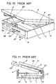
- FIG. 10 is a perspective view of a conventional disk recording or playback device commercially available
- FIG. 11 is a side elevation showing a cabinet 2 of FIG. 10 only in section.
- Pivoted as at 91 to a chassis 1 within the cabinet 2 are a lid 8 and a base end of a holder 9 for accommodating the cartridge 60.
- the lid 8 and the holder 9 are pivotally movable together.
- Disposed inside the front wall of the cabinet 2 is a slide member 4 movable leftward or rightward.
- the slide member 4 is provided with a hook piece 40 engageable with the lid 8, and a knob 43 projecting forward through a slit 20 in the front wall of the cabinet 2.
- the slide member 4 is biased by a spring 42 in a direction for the hook piece 40 to engage with the lid 8. When the knob 43 is pushed by hand against the force of the spring 42, the hook piece 40 is disengaged from the lid 8.
- the chassis 1 is provided with a restraining piece 5 retractably movable toward the slide member 4 by a drive mechanism (not shown).
- a head lever 71 positioned on the holder 9 and carrying the recording head 72 on its forward end.
- the holder 9, with the cartridge 60 inserted therein, is lowered by pushing by hand, while the head lever 71 is lowered by a lift mechanism (not shown).
- the recording head 72 is brought into contact with the disk 6 to record signals thereon.
- the chassis 1 is attached to the cabinet 2 by cushion members 10 and made movable to and fro sideways relative to the cabinet 2, whereby vibration, shake or impact given to the cabinet 2 is prevented from acting directly on the chassis 1, precluding the head lever 71 from jumping.
- the hook piece 40 of the slide member 4 engages with the lid 8 as seen in FIG. 12.
- the restraining piece 5 is moved toward the slide member 4 to fit the forward end of the piece into an opening 48 of the slide member 4.
- a clearance H (see FIG. 13) in the opening 48 alongside the restraining piece 5 serving as an allowance is smaller than an allowance provided for the engagement of the hook piece 40 with the lid 8, such that even if the user inadvertently pushes the knob 43 sideways by hand, the lid 8 will not be released from the hook piece 40. Since the lid 8 and the holder 9 do not open inadvertently during recording, the cartridge 60 will not move away from the pickup 7, ensuring a stabilized operation for recording signals on the disk 6.
- the conventional device nevertheless has the following problem.
- the restraining piece 5 is attached to the chassis 1, which is made movable to and fro within the cabinet 2 by the cushion members 10. If the clearance H is small in this case, the amount the chassis 1 is allowed to move to and fro sideways relative to the cabinet 2 is small. Accordingly, when the cabinet 2 is subjected to vibration or is shaken, the restraining piece 5 is liable to contact an edge of the opening portion 48, delivering the shake to the chassis 1 easily. Consequently, the head lever 71 jumps to result in an unstable recording operation, and the cushion members 10 provided become less effective. Further if the clearance H is small, the chassis 1 needs to be installed in the cabinet 2 with high accuracy since errors are not allowable in positioning the chassis 1 relative to the cabinet 2.
- An object of the present invention is to provide a device of the type described wherein the slide member is locked during recording of signals while permitting movement of the chassis and the restraining piece, with the slide member held in its locked position, when the device is subjected to external impact.
- a slide member 4 engageable with and disengageable from a lid 8 as pivotally moved to a lowered position is provided with a latch member 3 having a wide pushable surface orthogonal to the direction of retractable movement of a restraining piece 5 and movable along the direction of retractable movement of the restraining piece 5.
- the latch member 3 is movable between a locking position in which the latch member 3 is engaged with a cabinet 2 by being pushed by the restraining piece 5 to prevent the movement of the slide member 4 when signals are recorded on a disk and a standby position in which the latch member 3 is free from the pushing contact of the restraining piece 5 to permit the movement of the slide member 4 in a mode other than the recording.
- the restraining piece 5 and a chassis 1 are movable along the direction of movement of the slide member 4 within a range in which the restraining piece 5 is in pushing contact with the pushable surface of the latch member 3 in the locking position.
- the latch member 3 is in the locking position, i.e., in engagement with the cabinet 2 by being pushed by the restraining piece 5, preventing the movement of the slide member 4.
- the latch member 3 is held pushed toward the cabinet by the restraining piece 5.
- the slide member 4 remains immovable even when the chassis 1 moves along the direction of movement of the slide member 4 within the range in which the restraining piece 5 is in pushing contact with the pushable surface of the latch member 3.
- the restraining piece 5 and the chassis 1 While holding the latch member 3 pushed toward the cabinet 2, the restraining piece 5 and the chassis 1 are movable along the direction of movement of the slide member 4 with an allowance involved, and are allowed to move more greatly than in the conventional arrangement. Further the restraining piece 5 and the chassis 1 are allowed to move in a direction orthogonal to the direction of movement of the slide member 4 if the latch member 3 is in engagement with the cabinet 2.
- the chassis 1 is free to move to and fro along the direction of movement of the slide member 4, i.e., leftward or rightward, or forward or backward. This diminishes the likelihood that the shake will be delivered to the chassis 1 to ensure a stabilized recording operation.
- the chassis 1 is allowed to move to and fro greatly, with the latch member 3 in engagement with the cabinet 2, consequently ensuring a stabilized recording operation in spite of shaking that could occur, even if the engagement of the latch member 3 with the cabinet 2 involves a diminished clearance.
- the clearance is thus reduced, the movement of the slide member 4 can be restrained reliably, obviating the likelihood of the lid 8 and the holder 9 opening inadvertently.
- chassis 1 can be positioned relative to the cabinet 2 with a greater lateral allowance involved than conventionally, high accuracy will not be required in installing the chassis 1 in the cabinet 2.
- FIG. 5 is a perspective view of a cartridge 60 for use in a signal recording or reproduction device for a disk 6.
- the cartridge 60 has a groove 62 formed in one side portion thereof and covered with a shutter 61.
- the cartridge 60 contains the disk 6, which is partly exposed when the shutter 61 is open.
- the cartridge 60 is inserted into the device with an arrow 63 on its upper surface directed toward the device.
- FIG. 1 is a perspective view of the signal recording or reproduction device.
- a cabinet 2 has a lid 8 pivoted to one end thereof and a chassis 1 disposed therein. Pivoted to the chassis 1 is a holder 9 for holding the cartridge 60 therein. The holder 9 is connected to the lid 8 as will be described later and pivotally movable therewith.
- the slide member 4 is movable leftward or rightward as supported by the pins 23, 23 fitting in the slits 49, 49.
- the slide member 4 has a projecting hook piece 40 formed with a slope 41 and is biased rightward by a spring 42 connected between the member 4 and the cabinet 2.
- a knob 43 projecting from the slide member 4 extends through a slit 20 in the front wall of the cabinet 2 and is manually moved by the user.
- FIG. 2 is a side elevation in section of the cabinet 2 as it is seen in the direction of arrow Z in FIG. 1.
- the aperture 44 has fitted therein a latch member 3 L-shaped in section and supported at a lower end portion thereof by a pivot 30 on the lug 45.
- the latch member 3 has a pushable surface extending laterally, is biased clockwise by a torsion spring (not shown) fitted to the pivot 30 and has an upper end portion in contact with the upper side of the apertured portion 44.
- the front wall of the cabinet 2 has an opening 21 opposed to the latch member 3 and slightly greater than the latch member 3 in lateral width.
- the chassis 1 is attached to the cabinet 2 by cushion members 10 of urethane rubber or the like, and is movable to and fro sideways relative to the cabinet 2 (see FIG. 8), such that even if the cabinet 2 is shaken, the shake to be delivered to the chassis 1 is attenuated, preventing the head lever 71 to be described later from jumping.
- the chassis 1 is provided under the lower surface thereof with a restraining piece 5 opposed to the latch member 3 and retractably movable toward the slide member 4.
- the forward end of the restraining piece 5 is opposed to a portion of the latch member 3 above the pivot 30 thereof.
- the restraining piece 5 moves toward the slide member 4 to push the pushable surface of the latch member 3.
- FIG. 3 is an exploded perspective view of the chassis 1 and the holder 9.
- Plate springs 90, 90 each have one end attached to the upper surface of the holder 9 and the other end attached to the rear surface of the lid 8 deformably through deflection (see FIG. 8).
- Projecting from a side wall of the holder 9 is a lug 93 for opening the shutter 61 of the cartridge 60 by advancing into the groove 62 thereof (see FIG. 5). The shutter 61 is open when the cartridge 60 is in the holder 9.
- a motor M1 having a drive shaft 52 in mesh with an intermediate gear 51.
- the restraining piece 5 has a rear end formed with a rack 50, which is in mesh with the intermediate gear 51.
- the restraining member 5 is advanced from or retracted toward the chassis 1 by the rotation of the motor M1.
- the chassis 1 has an opening 11 provided therein with a turntable 70 for rotating the disk 6 and a pickup 7 movable toward or away from the turntable 70 for projecting a laser beam on the disk 6.
- a bracket 73 is attached to the rear side of the pickup 7, and the head lever 71 has a base end pivoted as at 74 to an upper end portion of the bracket 73.
- the head lever 71 is positioned between the upper surface of the holder 9 and the rear surface of the lid 8 (see FIG. 11).
- a recording head 72 is mounted on a free end of the head lever 71.
- the head lever 71 is in a raised position as shown in FIG. 4 while the device is in a mode other than a recording mode, for example, when the device is a playback mode or out of operation.
- the pickup 7 projects a laser beam of lower output level than when recording so as not to disturb the direction of magnetization on the disk 6.
- the beam reflected from an S pole on the disk 6 differs from the beam reflected from an N pole thereon in the inclination of plane of polarization, so that signals of 0 and 1 levels are detected from this difference of inclination.
- the head lever 71 is pivotally moved down by a lift mechanism (not shown) as seen in FIG. 4B, causing the recording head 72 to pass through an opening 92 (see FIG. 3) in the wall of the holder 9 and come into contact with the disk 6 in the cartridge 60.
- the pickup 7 projects a laser beam on the disk 6 as previously stated, while the recording head 72 is energized to record signals on the disk 6.
- FIG. 7 is a plan view of the holder 9 and the lid 8 as opened.
- the lid 8 has an engaging piece 80 inside of its front end.
- the engaging piece 80 comes into contact with the slope 41 of the hook piece 40, pushing the slide member 4 leftward against the action of the spring 42.
- the slide member 4 is returned by the spring 42, bringing the hook piece 40 into engagement with the engaging piece 80.
- the lid 8 is in its closed position, the holder 9 is in contact with the chassis 1, and the plate springs 90, 90 on the holder 9 are elastically deformed with their upper ends pressed by the lid 8 as seen in FIG. 8.
- FIGS. 6A and 6B are plan views showing the slide member 4 and the cabinet 2 in horizontal section, FIG. 6A showing the device in a mode other than the recording mode, FIG. 6B showing the device during recording.
- the restraining piece 5 In the mode other than the recording mode, the restraining piece 5 is in a retracted position with its forward end located away from the latch member 3, and the upper end of the latch member 3 is in contact with the slide member 4 as indicated in a solid line in FIG. 2. When thus positioned, the latch member 3 is in a standby position.
- the restraining piece 5 moves toward the latch member 3 and pushes the latch member 3.
- the latch member 3 moves about the pivot 30 on the slide member 4 to fit its upper end into the opening 21 of the cabinet 2.
- the slide member 4 is restrained from moving by the advance of the latch member 3 into the opening 21 as shown in FIG. 6B, preventing disengagement of the lid 8 from the slide member 4.
- This position of the latch member 3 is a locking position.
- the slide member 4 is restrained from moving toward a lid releasing direction by the latch member 3 brought to its locking position and fitted in the cabinet 2.
- the restraining piece 5 needs only to hold the latch member 3 pushed toward the cabinet 2, and the restraining piece 5 and the chassis 1 are movable leftward or rightward within the range of the lateral width of the latch member 3. If the latch member 3 is given an increased lateral width, the restraining piece 5 and the chassis 1 are movable to and fro laterally over a greater range. This diminishes the likelihood that a shake, if given to the cabinet 2, will be delivered to the chassis 1.
- the arrangement of the present embodiment is usable also in recording or playback devices wherein no cushion member 10 is provided.
- the chassis 1 is allowed to move to and fro greatly, with the latch member 3 in engagement with the cabinet 2, consequently ensuring a stabilized recording operation in spite of shaking that could occur, even if the engagement of the latch member 3 with the cabinet 2 involves a diminished clearance.
- the clearance is thus reduced, the movement of the slide member 4 can be restrained accurately.
- the latch member 3 of the embodiment described is pivoted at its lower end to the slide member 4, whereas the latch member 3 may be made of an elastic material so as to be elastically deformable by the movement of the restraining piece 5 and advance into the opening 21 of the cabinet 2.
- other means is usable insofar as the means causes the slide member 4 to engage with the cabinet 2 when pushed by the restraining piece 5.
Landscapes
- Feeding And Guiding Record Carriers (AREA)
- Optical Recording Or Reproduction (AREA)
- Holding Or Fastening Of Disk On Rotational Shaft (AREA)
Applications Claiming Priority (2)
| Application Number | Priority Date | Filing Date | Title |
|---|---|---|---|
| JP5671599 | 1999-03-04 | ||
| JP05671599A JP3370001B2 (ja) | 1999-03-04 | 1999-03-04 | ディスクへの信号記録又は再生装置 |
Publications (3)
| Publication Number | Publication Date |
|---|---|
| EP1033708A2 true EP1033708A2 (de) | 2000-09-06 |
| EP1033708A3 EP1033708A3 (de) | 2000-12-06 |
| EP1033708B1 EP1033708B1 (de) | 2004-12-29 |
Family
ID=13035191
Family Applications (1)
| Application Number | Title | Priority Date | Filing Date |
|---|---|---|---|
| EP00104278A Expired - Lifetime EP1033708B1 (de) | 1999-03-04 | 2000-03-01 | Plattenaufzeichnungs- oder Wiedergabegerät |
Country Status (4)
| Country | Link |
|---|---|
| US (1) | US6407971B1 (de) |
| EP (1) | EP1033708B1 (de) |
| JP (1) | JP3370001B2 (de) |
| DE (1) | DE60016993T2 (de) |
Cited By (1)
| Publication number | Priority date | Publication date | Assignee | Title |
|---|---|---|---|---|
| FR2852581A1 (fr) * | 2003-03-21 | 2004-09-24 | Cellon France Sas | Boitier comportant un volet de fermeture d'un orifice qui commande les moyens de verrouillage de l'ouverture du boitier |
Families Citing this family (3)
| Publication number | Priority date | Publication date | Assignee | Title |
|---|---|---|---|---|
| TW508054U (en) * | 2001-09-28 | 2002-10-21 | Lite On It Corp | Rotation device of compact disc player lid |
| CN2706834Y (zh) * | 2004-05-28 | 2005-06-29 | 鸿富锦精密工业(深圳)有限公司 | 光盘播放器顶盖启闭装置 |
| CN2731642Y (zh) * | 2004-08-28 | 2005-10-05 | 鸿富锦精密工业(深圳)有限公司 | 光盘驱动器防爆碟装置 |
Family Cites Families (9)
| Publication number | Priority date | Publication date | Assignee | Title |
|---|---|---|---|---|
| AT364546B (de) * | 1979-08-07 | 1981-10-27 | Philips Nv | Aufzeichnungs- und/oder wiedergabegeraet |
| JPS6040567A (ja) * | 1983-08-12 | 1985-03-02 | Canon Inc | 記録又は再生装置 |
| JPH0812739B2 (ja) * | 1985-02-07 | 1996-02-07 | キヤノン株式会社 | 画像記録装置 |
| JPH087910B2 (ja) * | 1986-04-11 | 1996-01-29 | キヤノン株式会社 | 記録再生装置 |
| DE69229495T2 (de) * | 1991-12-11 | 1999-12-16 | Sony Corp., Tokio/Tokyo | Lademechanismus von Plattenkassette für Gebrauch in Plattenaufzeichnungs- und/oder Wiedergabevorrichtung |
| MY112103A (en) * | 1993-08-26 | 2001-04-30 | Sony Corp | Recording and / or reproducing apparatus for recording medium and damper mechanism employed in such apparatus. |
| JPH0765496A (ja) * | 1993-08-26 | 1995-03-10 | Sony Corp | 記録媒体装着装置、及び、記録及び/又は再生装置 |
| KR100434580B1 (ko) * | 1995-07-13 | 2004-09-04 | 소니 가부시끼 가이샤 | 디스크이젝트장치및디스크카트리지의로딩장치 |
| US6028737A (en) * | 1998-03-25 | 2000-02-22 | Castlewood Systems, Inc. | Removable drive cover having flush surface |
-
1999
- 1999-03-04 JP JP05671599A patent/JP3370001B2/ja not_active Expired - Fee Related
-
2000
- 2000-03-01 EP EP00104278A patent/EP1033708B1/de not_active Expired - Lifetime
- 2000-03-01 DE DE60016993T patent/DE60016993T2/de not_active Expired - Fee Related
- 2000-03-03 US US09/518,259 patent/US6407971B1/en not_active Expired - Fee Related
Cited By (1)
| Publication number | Priority date | Publication date | Assignee | Title |
|---|---|---|---|---|
| FR2852581A1 (fr) * | 2003-03-21 | 2004-09-24 | Cellon France Sas | Boitier comportant un volet de fermeture d'un orifice qui commande les moyens de verrouillage de l'ouverture du boitier |
Also Published As
| Publication number | Publication date |
|---|---|
| EP1033708B1 (de) | 2004-12-29 |
| DE60016993D1 (de) | 2005-02-03 |
| EP1033708A3 (de) | 2000-12-06 |
| US6407971B1 (en) | 2002-06-18 |
| DE60016993T2 (de) | 2006-03-30 |
| JP3370001B2 (ja) | 2003-01-27 |
| JP2000260090A (ja) | 2000-09-22 |
Similar Documents
| Publication | Publication Date | Title |
|---|---|---|
| EP0825600B1 (de) | Plattenaufzeichnungs- und/oder -wiedergabegerät | |
| JPS5812662B2 (ja) | デイスク・カ−トリツジ記録・再生装置 | |
| JP2679231B2 (ja) | カセットローディング機構 | |
| US3904149A (en) | Cassette loading apparatus for use in cassette tape recorder | |
| CN1003686B (zh) | 盒式磁盘装载装置 | |
| US6407971B1 (en) | Disk recording or playback device | |
| CS122187A2 (en) | Recording and/or reproducing apparatus | |
| US4833553A (en) | Magnetic disc cartridge loading and unloading mechanism | |
| US5815344A (en) | Disc cartridge loading apparatus | |
| EP0204921B1 (de) | Verfahren und Vorrichtung zur Kassettenführung | |
| US5784351A (en) | Loading apparatus for disk cartridge | |
| US5943186A (en) | Cartridge retention mechanism for a removable cartridge drive | |
| US4651240A (en) | Disk cartridge loading and ejecting mechanism in a recording and playback apparatus | |
| JPH09167422A (ja) | ディスク再生装置及びそれに用いられる互換カートリッジ | |
| US6707638B2 (en) | Slider impedance mechanism to prevent cartridge ejection during operation | |
| US5757577A (en) | Magnetic recording-playback apparatus for cassettes of two different sizes | |
| US6181511B1 (en) | Platform forward latch with locking feature | |
| US6239946B1 (en) | Magnetic disk drive | |
| US6829773B1 (en) | Device for recording or reproducing signal on or from disk with a releasing mechanism | |
| US7023654B2 (en) | Disk cartridge ejection mechanism and method | |
| JP2530140B2 (ja) | デイスクロ−デイング機構 | |
| JPH05250837A (ja) | ディスクカートリッジ | |
| JPH04335247A (ja) | カセット装着装置 | |
| JPS63853A (ja) | 記録再生装置におけるディスクカセットの摺動蓋開蓋装置 | |
| JPH08212660A (ja) | 記録再生装置及び記録媒体用カートリッジ |
Legal Events
| Date | Code | Title | Description |
|---|---|---|---|
| PUAI | Public reference made under article 153(3) epc to a published international application that has entered the european phase |
Free format text: ORIGINAL CODE: 0009012 |
|
| AK | Designated contracting states |
Kind code of ref document: A2 Designated state(s): DE GB |
|
| AX | Request for extension of the european patent |
Free format text: AL;LT;LV;MK;RO;SI |
|
| PUAL | Search report despatched |
Free format text: ORIGINAL CODE: 0009013 |
|
| AK | Designated contracting states |
Kind code of ref document: A3 Designated state(s): AT BE CH CY DE DK ES FI FR GB GR IE IT LI LU MC NL PT SE |
|
| AX | Request for extension of the european patent |
Free format text: AL;LT;LV;MK;RO;SI |
|
| 17P | Request for examination filed |
Effective date: 20010122 |
|
| AKX | Designation fees paid |
Free format text: DE GB |
|
| 17Q | First examination report despatched |
Effective date: 20030220 |
|
| GRAP | Despatch of communication of intention to grant a patent |
Free format text: ORIGINAL CODE: EPIDOSNIGR1 |
|
| GRAS | Grant fee paid |
Free format text: ORIGINAL CODE: EPIDOSNIGR3 |
|
| GRAA | (expected) grant |
Free format text: ORIGINAL CODE: 0009210 |
|
| AK | Designated contracting states |
Kind code of ref document: B1 Designated state(s): DE GB |
|
| REG | Reference to a national code |
Ref country code: GB Ref legal event code: FG4D |
|
| REF | Corresponds to: |
Ref document number: 60016993 Country of ref document: DE Date of ref document: 20050203 Kind code of ref document: P |
|
| PLBE | No opposition filed within time limit |
Free format text: ORIGINAL CODE: 0009261 |
|
| STAA | Information on the status of an ep patent application or granted ep patent |
Free format text: STATUS: NO OPPOSITION FILED WITHIN TIME LIMIT |
|
| 26N | No opposition filed |
Effective date: 20050930 |
|
| PGFP | Annual fee paid to national office [announced via postgrant information from national office to epo] |
Ref country code: DE Payment date: 20070222 Year of fee payment: 8 |
|
| PGFP | Annual fee paid to national office [announced via postgrant information from national office to epo] |
Ref country code: GB Payment date: 20070228 Year of fee payment: 8 |
|
| GBPC | Gb: european patent ceased through non-payment of renewal fee |
Effective date: 20080301 |
|
| PG25 | Lapsed in a contracting state [announced via postgrant information from national office to epo] |
Ref country code: DE Free format text: LAPSE BECAUSE OF NON-PAYMENT OF DUE FEES Effective date: 20081001 |
|
| PG25 | Lapsed in a contracting state [announced via postgrant information from national office to epo] |
Ref country code: GB Free format text: LAPSE BECAUSE OF NON-PAYMENT OF DUE FEES Effective date: 20080301 |