EP1033716A1 - Cartouche de disque - Google Patents
Cartouche de disque Download PDFInfo
- Publication number
- EP1033716A1 EP1033716A1 EP99935100A EP99935100A EP1033716A1 EP 1033716 A1 EP1033716 A1 EP 1033716A1 EP 99935100 A EP99935100 A EP 99935100A EP 99935100 A EP99935100 A EP 99935100A EP 1033716 A1 EP1033716 A1 EP 1033716A1
- Authority
- EP
- European Patent Office
- Prior art keywords
- disc
- body unit
- cartridge body
- liner
- main
- Prior art date
- Legal status (The legal status is an assumption and is not a legal conclusion. Google has not performed a legal analysis and makes no representation as to the accuracy of the status listed.)
- Withdrawn
Links
Images





Classifications
-
- G—PHYSICS
- G11—INFORMATION STORAGE
- G11B—INFORMATION STORAGE BASED ON RELATIVE MOVEMENT BETWEEN RECORD CARRIER AND TRANSDUCER
- G11B23/00—Record carriers not specific to the method of recording or reproducing; Accessories, e.g. containers, specially adapted for co-operation with the recording or reproducing apparatus ; Intermediate mediums; Apparatus or processes specially adapted for their manufacture
- G11B23/02—Containers; Storing means both adapted to cooperate with the recording or reproducing means
- G11B23/03—Containers for flat record carriers
- G11B23/033—Containers for flat record carriers for flexible discs
- G11B23/0332—Containers for flat record carriers for flexible discs for single discs, e.g. envelopes
-
- G—PHYSICS
- G11—INFORMATION STORAGE
- G11B—INFORMATION STORAGE BASED ON RELATIVE MOVEMENT BETWEEN RECORD CARRIER AND TRANSDUCER
- G11B23/00—Record carriers not specific to the method of recording or reproducing; Accessories, e.g. containers, specially adapted for co-operation with the recording or reproducing apparatus ; Intermediate mediums; Apparatus or processes specially adapted for their manufacture
- G11B23/02—Containers; Storing means both adapted to cooperate with the recording or reproducing means
- G11B23/03—Containers for flat record carriers
- G11B23/0301—Details
- G11B23/0308—Shutters
-
- G—PHYSICS
- G11—INFORMATION STORAGE
- G11B—INFORMATION STORAGE BASED ON RELATIVE MOVEMENT BETWEEN RECORD CARRIER AND TRANSDUCER
- G11B23/00—Record carriers not specific to the method of recording or reproducing; Accessories, e.g. containers, specially adapted for co-operation with the recording or reproducing apparatus ; Intermediate mediums; Apparatus or processes specially adapted for their manufacture
- G11B23/50—Reconditioning of record carriers; Cleaning of record carriers ; Carrying-off electrostatic charges
- G11B23/505—Reconditioning of record carriers; Cleaning of record carriers ; Carrying-off electrostatic charges of disk carriers
-
- G—PHYSICS
- G11—INFORMATION STORAGE
- G11B—INFORMATION STORAGE BASED ON RELATIVE MOVEMENT BETWEEN RECORD CARRIER AND TRANSDUCER
- G11B2220/00—Record carriers by type
- G11B2220/20—Disc-shaped record carriers
- G11B2220/25—Disc-shaped record carriers characterised in that the disc is based on a specific recording technology
- G11B2220/2508—Magnetic discs
Definitions
- This invention relates to a disc cartridge housing a disc-shaped recording medium, such as a magnetic disc, having a center core at the center thereof for clamping to a rotating driving unit. More particularly, it relates to a disc cartridge having a main body unit of a cartridge housing a disc-shaped recording medium and the inner surface of which is provided with a liner for protecting a disc-shaped recording medium.
- a disc cartridge which is provided with a main cartridge body unit, obtained on abutting and connecting a pair of upper and lower cartridge halves to each other, and in which a magnetic disc having a flexible disc substrate and a magnetic layer formed thereon is rotationally mounted in the main cartridge body unit.
- a liner constituted by a non-woven cloth, on the inner surface of each of the upper and lower cartridge halves, constituting the main cartridge body unit, for cleaning the magnetic disc housed within the main cartridge body unit and for protecting the magnetic disc.
- the liner provided on the inner surface of the upper cartridge half, has its portion lifted towards the side of the magnetic disc by plural ribs formed like comb-teeth on the inner surface of the upper cartridge half.
- the liner, mounted on the inner surface of the lower cartridge half has its portion lifted towards the side of a magnetic disc by plural ribs formed in a comprising:-teeth-like pattern on the inner surface of the upper cartridge half.
- the disc cartridge according to the present invention proposed for accomplishing the above object, includes a main cartridge body unit formed on abutting and interconnecting upper and lower cartridge halves for rotationally housing a disc-shaped recording medium having a clamp at its center for clamping the rotating driving unit.
- a recording/reproducing aperture for exposing a portion of the signal recording region of the disc-shaped recording medium to outside across the radial direction.
- a center opening for exposing the clamp mounted on the disc-shaped recording medium to outside.
- On each opposite inner surface of the main cartridge body unit is mounted a liner. This liner has an adhesive portion and a non-adhesive portion for the main cartridge body unit.
- a non-air-permeable layer On the surface of the non-adhesive portion facing the inner surface of the main cartridge body unit is formed a non-air-permeable layer.
- the non-adhesive portion of the liner is positioned in an upstream side region with respect to the recording/reproducing aperture looking along the direction of rotation of the disc-shaped recording medium in the main cartridge body unit.
- the liner used is made up of an air-permeable main liner member, formed by a non-woven clot, and a non-air-permeable layer formed on the entire surface of the main liner member facing the inner surface of the main cartridge body unit.
- the non-air-permeable layer is formed by coating a high molecular material on a surface of the main liner member facing the inner surface of the main cartridge body unit.
- the high molecular material used exhibits thermal sensitivity.
- the non-adhesive portion By forming a bend on the liner at or near the boundary between the adhesive portion and the non-adhesive portion, the non-adhesive portion can be approached towards and reliably contacted with the disc-shaped recording medium.
- a liner having a non-air-permeable thermally sensitive adhesive layer on its one surface is provided on the facing inner surfaces of the main cartridge body unit for sandwiching the disc-shaped recording medium.
- Each of the liners has an adhesive portion, having a thermally sensitive adhesive layer banded to the inner surface of the main cartridge body unit, and a non-adhesive portion that can be separated from the inner surface of the main cartridge body unit. At least a portion of the inner surface of the main cartridge body unit facing the non-adhesive portion is formed as a roughed surface.
- the non-adhesive portion is prevented from being affixed to the inner surface of the main cartridge body unit so that the non-adhesive portion is separated from the inner surface of the main cartridge body unit to assure reliable contact thereof with the disc-shaped recording medium.
- the non-adhesive portion of the liner is located in an upstream side area with respect to the recording/reproducing aperture looking in the direction of rotation of the disc-shaped recording medium in the main cartridge body unit.
- the liner is formed with a bend facing the planar portion of the main cartridge body unit at or near the boundary between the adhesive portion and the non-adhesive portion with respect to the main cartridge body unit. This bend is formed by being pressed by a lug formed in a thermal welding hone used for bonding the liner to the inner surface of the main cartridge body unit.
- the magnetic disc 5 housed within the main cartridge body unit 4 includes a main disc member 6, approximately 3.5 inch in diameter, comprised of a thin flexible synthetic resin film having magnetic layers deposited on both surfaces thereof.
- the center portion of the main disc member 6 has a center opening 7, and a center core 8 mounted on the main disc member 6 as by fitting the center core in the center opening 7, as shown in Fig.4.
- the center core 8 is formed of a magnetic material, such as metal.
- the center core 8 has a flat tubular swollen-out portion 9 at its center, and a flange 10 operating as a mounting portion to the main disc member 6 is formed as one with the upper end of the swollen-out portion 9.
- a spindle shaft inserting opening 11 engaged by a spindle shaft constituting the disc rotating driving unit
- a driving pin engagement opening 12 engaged by a driving pin provided on the disc rotating driving unit.
- up standing wall sections 11a, 12a Around the spindle shaft inserting opening 11 and the driving pin engagement opening 12 are formed up standing wall sections 11a, 12a.
- the up standing wall sections 11a, 12a support the peripheral surfaces of the spindle shaft and the driving pin over broad surfaces to effect reliable engagement of the spindle shaft and the driving pin in the spindle shaft inserting opening 11 and the driving pin engagement opening 12, respectively.
- a disc setting portion 13 for a disc table of the disc rotating driving unit.
- the disc setting portion 13 is formed by providing the bottom 9a of the swollen-out portion 9 with a recess to prevent deviation of the loading position of the magnetic disc with respect to the disc table.
- the main cartridge body unit 4 housing the disc 5, constructed by abutting and interconnecting upper and lower cartridge halves 2, 3, formed to a subsequently rectangular shape by injection molding the synthetic resin, as shown in Figs. 1 to 3.
- partitioning wall forming wall sections 23, 24 for constituting a partitioning wall section 22 delimiting a disc housing section 21 adapted for rotatably housing the magnetic disc 5, as shown in Figs. 5 and 6.
- These partitioning wall forming wall sections 23, 24 are formed as an arc inscribing the rectangular upper and lower cartridge halves 2, 3, as shown in Figs.5 and 6.
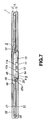
- the partitioning wall forming wall sections 23, 24 are abutted against each other to constitute the partitioning wall section 22, as shown in Fig.7, with the area surrounded by the partitioning wall section 22 serving as the disc housing section 21.
- partitioning wall section 22 constituting the disc housing section 21 is formed by abutting the partitioning wall forming wall sections 23, 24, formed arcuately to inscribe the rectangular upper and lower cartridge halves 2, 3, the partitioning wall section 22 encircles substantially the entire periphery of the magnetic disc 5 housed in the disc housing section 21.
- a circular center opening 25 for allowing the swollen-out portion 9 of the center core 8 mounted on the magnetic disc 5 housed within the main cartridge body unit 4 to be exposed to outside, as shown in Figs.2 and 3.
- the center opening 25 is a provided only on the lower cartridge half 3, while the center portion of the upper surface of the main cartridge body unit 2 constituted by the upper cartridge half 2 remains solid, as shown in Figs. 1 and 3.
- a first recording/reproducing aperture 26 and a second recording/reproducing aperture 27 for allowing at least a portion of the signal recording region of the magnetic disc housed in the main cartridge body unit 4 to be exposed to outside across the disc radial direction.
- These recording/reproducing apertures 26, 27 are formed substantially rectangular in shape and extend from the center portion in the vicinity of the center opening 25 in the left-and-right direction of the main cartridge body unit 4 to the vicinity of the front wall section 15 of the main cartridge body unit 4.
- the first and second recording/reproducing apertures 26, 27 are formed from the disc housing section 21 to the position proximate to the front wall section 15 so that the magnetic head constituting the recording/reproducing means for information signals, intruded into the inside of the main cartridge body unit 4, will scan the magnetic disc 5 housed in the main cartridge body unit 4 via these openings 26, 27 as far as the outer rim of the magnetic disc 5 housed int the main cartridge body unit 4, as shown in Figs.5 and 6.
- the shutter member 28 for opening/closing the first and second recording/reproducing apertures 26, 27, as shown in Figs. 1 and 2.
- the shutter member 28, constructed as described above, is mounted on the main cartridge body unit 4, by inserting the first and second shutter portions 29, 30 onto the main cartridge body unit 4 from the front wall section 15 so that the first and second shutter portions 29, 30 will be extended over the first and second recording/reproducing apertures 26, 27, the first and second cartridge holding portions 32, 33 are fitted on the front wall section 15 of the main cartridge body unit 5 and the paired engagement pieces 36, 37 are engaged in the movement guide grooves 34, 35.
- the shutter member 28, thus mounted on the main cartridge body unit 4, has the engagement pieces 36, 37 guided by the movement guide grooves 34, 35 and is moved in this manner in the direction indicated by arrows A and B in Figs.1 and 2 between a position in which the first and second shutter portions 29, 30 close the first and second recording/reproducing apertures 26, 27, respectively, and a position in which the first and second shutter portions 29, 30 open the first and second recording/reproducing apertures 26, 27, respectively.
- a disc movement limiting rib 45 for limiting the movement of the magnetic disc 5, as shown in Fig.7.
- This disc movement limiting rib 45 is of a circular shape having an outer diameter that can be introduced into the swollen-out portion 9 of the center core 8 provided on the magnetic disc 5.
- the disc movement limiting rib 45 is intruded into the swollen-out portion 9, as shown in Fig.7, to restrict movement in the planar direction of the magnetic disc 5.
- the disc movement limiting rib 45 prevents the outer rim of the magnetic disc 5 from being deformed by abutting contact against the partitioning wall section 21 to protect the flexible magnetic disc 5.
- annular recess 46 into which is intruded the flange 10 of the center core 8 when the magnetic disc 5 is supported by the disc movement limiting rib 45, as shown in Fig.7.
- annular recess 46 By forming the annular recess 46 in this manner, it is possible to prevent the flange 10 from contacting with the inner surface of the upper cartridge half 2 while the thickness of the main cartridge body unit 4 is reduced in thickness.
- an inclined surface 25a On the rim of the inner surface of the center opening 25 is formed an inclined surface 25a, as shown in Fig.7. This inclined surface 25a serves for providing clearance for the flange 10 of the center core 8 of an increased thickness.
- a ring-shaped rib 48 constituting a liner mounting portion 47 along with the partitioning wall section 22 for surrounding the annular recess 46, as shown in Fig.5.
- An area surrounded by the partitioning wall forming wall section 23 and the rib 48 serves as a liner mounting portion 47 formed to have a planar surface.
- a liner 49 for cleaning the magnetic disc 5 housed in the main cartridge body unit 4 and for protecting the magnetic disc 5, as shown in Fig.5.
- This liner 49 is formed as a ring sized to cover the major surface of the main disc member 6 constituting the magnetic disc 5.
- a cut-out 49a for opening the aperture 26, as shown in Figs.3 and 5.
- a liner arranging portion 50 having a planar surface.
- this liner arranging portion 50 is arranged a liner 51 adapted for cleaning the magnetic disc 5 housed within the main cartridge body unit 4 and for protecting the magnetic disc 5, as shown in Fig.6.
- This liner 51 is formed as a ring sized to cover the major surface of the main disc member 6 constituting the magnetic disc 5.
- a cut-out 51a for opening the aperture 27, as shown in Figs.3 and 6.
- the liners 49, 51 provided on the inner surfaces of the upper and lower cartridge halves 2, 3, are formed with cut-outs 49a, 51a in register with the first and second recording/reproducing apertures 26, 27. Both opposite side ends of the cut-outs 49a, 51a are designed as free ends.
- the liners 49, 51, provided on the opposite inner surfaces of the upper and lower cartridge halves 2, 3, have portions thereof as adhesive portions 52, 53 for the liner mounting portions 47, 50, while having other portions thereof as non-adhesive portions 54, 55, as shown in Figs.5 and 6. That is, the liners 49, 51 are arranged in the inside of the main cartridge body unit 4 so that the non-adhesive portions 54, 55 will be able to be isolated and floated from the respective inner surfaces of the upper and lower cartridge halves 2, 3, respectively.
- the liners 49, 51 are arranged on the respective inner surfaces of the upper and lower cartridge halves 2, 3 so that, if the main cartridge body unit 4 is split along a centerline L0 passing through the center O of the main cartridge body unit 4 to bi-sect the first and second recording/reproducing apertures 26, 27 provided in the upper and lower cartridge halves 2, 3, respectively, the non-adhesive portions 54, 55 will be positioned in an upstream side area of the rotating movement of the magnetic disc 5 within the main cartridge body unit 4 towards the first and second recording/reproducing apertures 26, 27 in the direction indicated by arrow R1 in Figs.5 and 6.
- the liners 49, 50 are arranged on the respective inner surfaces of the upper and lower cartridge halves 2, 3, so that, when the magnetic disc 5 is rotated in the direction indicated by arrow R1 in Figs.5 and 6 towards the first and second recording/reproducing apertures 26, 27, the non-adhesive portions 54, 55 will be positioned on the upstream side of the main cartridge body unit 4 corresponding to the intruding side of the main cartridge body unit 4 to the magnetic head as recording/reproducing means facing these apertures 26, 27 and so that the adhesive portions 52, 53 will be positioned in the downstream side area of the main cartridge body unit 4 in which the magnetic disc retreats from the magnetic head facing the apertures 26, 27.
- the disc cartridge 1 of the present invention is formed with an air exhaust opening 65 for exhausting air in the disc housing section 21 as a spacing surrounded by the partitioning wall section 22 to outside the main cartridge body unit 4, and an air exhaust passage 66 communicating with the air exhaust opening 65.
- the air exhaust opening 65 is formed by partially segmenting the front wall section 15 of the main cartridge body unit 7.
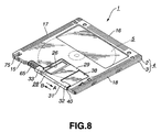
- the air exhaust opening 65 is provided at a position in which the opening 65 is closed by a portion of the shutter member 28 when the shutter member 28 is at the position of closing the first and second recording/reproducing apertures 26, 27, as shown in Figs. 1 and 2, and in which the opening 65 is opened when the shutter member 28 is moved to the position of opening the first and second recording/reproducing apertures 26, 27 as shown in Fig.8.
- the air exhaust opening 65 is formed by forming registering cut-outs 65a, 65b in portions of the upstanding wall sections 19, 20 of the upper and lower cartridge halves 2, 3 constituting the front wall section 15 of the main cartridge body unit 4, and by abutting the upstanding wall sections 19, 20 to each other, as shown in Figs.5 and 6.
- the magnetic disc 5, housed in the main cartridge body unit 4 is clamped by the rotating driving unit and run in rotation in the direction indicated by arrow R1 in Figs.5 and 6, there is generated in the disc housing section 21 a spirally-shaped air stream proceeding in the same direction as the rotation of the magnetic disc 5 from the center opening 25 towards the outer periphery, by rotation of the magnetic disc 5.
- a loading limiting portion 75 for inhibiting loading of the disc cartridge housing a magnetic disc having a recording capacity different from the recording capacity of the magnetic disc 5 of the disc cartridge according to the present invention.
- the loading limiting portion 75 is formed as a recess formed in the front wall section 15 of the main cartridge body unit 4.
- the first and second positioning reference holes 69, 70 are engaged by positioning pins 81, 82 provided on the disc recording/reproducing apparatus for setting the position in the horizontal direction, as shown in Fig.9.
- the disc cartridge 1 has its loading height position set by the corner portions towards the rear wall section 16 of the main cartridge body unit 4 being supported by height setting pins, not shown.
- a spindle motor not shown, constituting the disc rotating driving unit 83, is driven, as the magnetic disc is enabled to be rotated in unison with the disc table 84, the magnetic disc 5 is run in rotation in unison with the rotation of the disc table 84 about the spindle shaft 85 as a center of rotation.
- the spindle shaft 85 is inserted into the spindle shaft inserting opening 11
- the driving pin 86 is engaged in the driving pin engagement opening 12and the magnetic disc 5 is set on the disc table 84 in a state in which the magnetic disc 5 can be rotated in unison with the disc table 84, the magnetic disc 5 is floated from the lower cartridge half 3 constituting the main cartridge body unit 4 and is positioned at a mid position along the thickness of the main cartridge body unit 4.
- the shutter member 28 is moved by a shutter opening mechanism provided on the disc recording/reproducing apparatus, in the direction indicated by arrow A in Figs. 1 and 2, against the bias of the torsion coil spring 43, to open the first and second recording/reproducing apertures 26, 27.
- This also opens the air exhaust opening 65 provided in the front wall section 15 of the main cartridge body unit 4 as shown in Fig.8.
- the magnetic disc 5, loaded in position on the disc rotating driving unit 73 is run in rotation at at least 3000 rpm.
- the magnetic disc 5 of the preferred embodiment is run in rotation in a rpm range from 3000 to 3600. If the magnetic disc 5 is run in rotation at an elevated speed of 3000 to 3600 rpm, there is produced a spiral air stream in the disc housing section 21 along the rotating direction of the magnetic disc 5.
- This air stream which is spiral and proceeds from the center of the main cartridge body unit 4 towards its outer periphery, operates to attract air from the center opening 25 formed in the lower surface of the main cartridge body unit 4 in a direction indicated by arrow S in Fig.9. If air is attracted from the center opening 25, there is produced a spiral air stream R2 which sets a pressurized state in a region between the magnetic disc 5 and the lower cartridge half 3 constituting the lower surface of the main cartridge body unit 4.
- the liners used in the disc cartridge are provided for preventing the magnetic disc housed in the main cartridge body unit from being damaged by direct contact with the inner surface of the main cartridge body unit formed of a highly rigid synthetic resin, so that these liners are formed of a material which cannot damage the magnetic disc on contact with the magnetic disc. Therefore, the liners are usually formed of a flexible non-woven cloth, mainly composed of fibers, exemplified by cellulose, such as rayon (trade name). This type of the non-woven cloth is air permeable since it is an ensemble of fibers.
- the non-air-permeable layer 82 is formed by layering a non-air-permeable film of a high molecular material on one surface of the main liner member 81.
- the non-air-permeable film of a high molecular material may be exemplified by a film of polyethylene terephthalate (PET) or polyamide.
- the liner 49, 51 obtained on coating or layering the non-air-permeable layer 82 on a surface of the main liner member 81, is arranged with the main liner member 81 facing the magnetic disc 5 or with the non-air-permeable layer 82 facing the inner surfaces of the upper and lower cartridge halves 2, 3.
- the liners 49, 51 are bonded to the inner surfaces of the upper and lower cartridge halves 2, 3 using an adhesive.
- the center opening formed in the center of the main disc member and the rim portion of the center opening operate as clamping portions for the disc rotating driving unit.
- the bends, formed by compressing portions of the liners 49, 51, are improved in toughness by the non-adhesive portions 54, 55, so that the non-adhesive portions 54, 55 can be easily flexed with the bends as the center.
- the non-adhesive portions 54, 55 can be approached to the magnetic disc 5 and also can be easily flexed and deformed, so that, if the magnetic disc 5 is run in rotation, the non-adhesive portions 54, 55 can be reliably contacted with the magnetic disc 5 to achieve reliable cleaning of the magnetic disc 5.
- this disc cartridge 101 has the basic structure in common with the above-described disc cartridge 1, the common portions are depicted by common reference numerals and are not explained specifically.
- the disc cartridge 101 has a main cartridge body unit 104, obtained on abutting and connecting upper and lower cartridge halves 102, 103, obtained on injection molding the synthetic resin to a substantially rectangular shape, to each other.
- a magnetic disc 5 as a recording medium for information signals.
- the high molecular material exhibiting thermal bonding characteristics, constituting the thermal adhesive layer 153 is preferably such a material which is cured at a temperature lower than the melting point of the material of the main liner member 152 and which is bonded in this state to the upper and lower cartridge halves 102, 103.
- the liners 149, 151 are bonded to the inner surfaces of the upper and lower cartridge halves 102, 103 in such a state in which, when the main cartridge body unit 104 is divided along a centerline L0 bisecting the first and second recording/reproducing apertures 26, 27, provided in the upper and lower cartridge halves 102, 103, through the center O of the main cartridge body unit 104, the portions of the liners 149, 151 lying in an upstream side area of the magnetic disc 5 rotating in the direction indicated by arrow R1 in Figs.18 and 19 towards the first and second recording/reproducing apertures 26, 27 operate as non-adhesive portions 154, 155, while the portions of the liners 149, 151 lying in the downstream side area of the main cartridge body unit 104, with the magnetic disc 5 retreating from the apertures 26, 27, operate as adhesive portions 156, 157.
- the non-adhesive portions 154, 155 are separated from the inner surfaces of the upper and lower cartridge halves 102, 103 and flexurally deformed into contact with the major surface of the magnetic disc 5 rotationally driven in the main cartridge body unit 104 to clean the magnetic disc 5.
- the non-adhesive portions 154, 155 are of a length such that, when at least the magnetic disc 5 is run in rotation, the non-adhesive portions 154, 155 are separated from the inner surfaces of the upper and lower cartridge halves 102, 103 and flexurally deformed into contact with the major surface of the rotationally driven magnetic disc 5.
- the liners 149, 151 used are such that the main liner member 152 is constructed by a non-woven cloth mainly composed of fibers, such as cellulose, e.g., rayon (trade name), and the thermal adhesive layer 153 is formed of ethylene vinyl acetate, the non-adhesive portions 154, 155 are provided over angular ranges of ⁇ 1 and ⁇ 2 equal to approximately 40° to 45°, respectively, in the upstream side of the centerline L0 bisecting the first and second recording/reproducing apertures 26, 27 through the centerline O of the main cartridge body unit 104, into which the rotationally driven magnetic head 5 facing the first and second recording/reproducing apertures 26, 27 is about to be intruded from the upstream side, as shown in Figs.18, 19.
- the ranges of the non-adhesive portions 154, 155 may be suitably selected depending on the stiffness of the liners 149, 151 employed, however, if these ranges are set in excess of 180° from the centerline L0 bisecting the first and second recording/reproducing apertures 26, 27, there is the risk that the non-adhesive portions 154, 155 be not maintained in stability at a fixed position. Therefore, the above ranges are set to 180° or less and preferably to 100° or less.
- the portions other than the non-adhesive portions 154, 155 of the liners 149, 151 are designed as adhesive portions 156, 157 to the inner surfaces of the upper and lower cartridge halves 102, 103, as shown in Figs.18 and 19.
- the inner surfaces of the upper and lower cartridge halves 102, 103, carrying the liners 149, 151, have portions faced by the non-adhesive portions 154, 155, these portions being formed with rough surfaces 158, 159, as shown in Figs.21 and 22.
- These rough surfaces 158, 159 are provided for preventing occurrence of such status in which the load of, for example, the magnetic disc 5, is applied to the liners 149, 151 having the thermal adhesive layer 153 on the sides thereof facing the inner surfaces of the upper and lower cartridge halves 102, 103 to cause the non-adhesive portions 154, 155 to be affixed to the inner surfaces of the upper and lower cartridge halves 102, 103 to inhibit separation of the non-adhesive portions 154, 155 from the inner surfaces of the upper and lower cross-sectional halves 102, 103. That is, the function of the rough surfaces 158, 159 is to prevent the affixture of the non-adhesive portions 154, 155 to the inner surfaces of the upper and lower cross-sectional halves 102, 103.
- the rough surfaces 158, 159 are provided substantially in register with the portions of the liners 149, 151 carrying the non-adhesive portions 154, 155 and hence are provided in the angular ranges ⁇ 1 and ⁇ 2 of approximately 40 to 45° on the upstream side of the centerline L0 bisecting the first and second recording/reproducing apertures 26, 27, through the centerline O of the main cartridge body unit 104, into which the rotating magnetic disc 5 is intruded into the magnetic head facing the apertures 26, 27.
- these rough surfaces 158, 159 are formed in register with the non-adhesive portions 154, 155, these rough surfaces 158, 159, similarly to the non-adhesive portions 154, 155, are formed through an angular extent of 180° or less, desirably 100° or less, from the centerline L0 bisecting the first and second recording/reproducing apertures 26, 27.
- the main liner member 152 is constructed by a non-woven cloth, mainly composed of fibers, such as cellulose, e.g., rayon (trade name) and the thermal adhesive layer 153 is formed by ethylene vinyl acetate, to provide the liner 149 (151).
- the liners 149, 151 are set on plural test plates 201 having different surface roughnesses (Rz), as shown in Figs.23 and 24. On the liners 149, 151 were set weights of approximately 3 g, which is twice the weight of the center core 8 mounted on the 3.5 inch magnetic disc 5.
- the plate 201 with the surface roughness exceeding 20 ⁇ mRz was formed by molding an ABS resin, there occurred molding defects such as large protrusions ascribable to irregular release from a molding metal die.
- bends 161, 162 at or near a boundary between the adhesive portions 156, 157 and the non-adhesive portions 54, 55 to the upper and lower cartridge halves 102, 103 of the liners 149, 151 arranged on the inner surfaces of the upper and lower cartridge halves 102, 103, as shown in Figs.18 and 19. These bends are formed by linearly compressing portions of the main liner member 152 of non-woven cloths constituting the liners 149, 151 across the inner and outer rims.
- the lower cartridge half 103 is set on a welding table 211 of a thermal welding device, with the inner surface thereof facing upwards, as shown in Figs.25 and 26.
- the ring-shaped liner 151 is set in position on the inner surface of the lower cartridge half 103 for encircling the center opening 25.
- a thermal welding hone 212 of the thermal welding device and the thermal adhesive layer 153 provided on the liner 151 is fused by ultrasonic waves and bonded to the inner surface of the lower cartridge half 103 to mount the liner 151 on the inner surface of the lower cartridge half 103.
- the disc cartridge 101 shown here, is provided with the air exhaust opening 65 for exhausting the air in the disc housing section 21, as a space encircled by the partitioning wall section 22, to outside of the main cartridge body unit 4, and an air exhaust passage 66 communicating with the air exhaust opening 65.
- the air exhaust opening 65 is formed by partially segmenting the front wall section 15 of the main cartridge body unit 104, as in the case of the disc cartridge 1, described above, in such a position that, when the shutter member 28 is at the position of closing the first and second recording/reproducing apertures 26, 27, the air exhaust opening 65 is covered by a portion of the shutter member 28 and, when the shutter member 28 is moved to a position opening the first and second recording/reproducing apertures 26, 27, the air exhaust opening 65 is opened.
- the non-adhesive portion 154 of the liner 149 is flexed under its own weight towards the lower cartridge half 103, along the bend 161, until it is contacted with the major surface of the magnetic disc 5 positioned at a mid portion along the direction of thickness of the main cartridge body unit 104.
- the magnetic disc 5, loaded in position on the disc rotating driving unit 83 is run in rotation at an rpm exceeding at least 3000, for example, at an rpm between 3000 and 3600, there is generated an air stream in the disc housing section 21 flowing spirally along the direction of rotation of the magnetic disc 5.
- This air stream is a spiral stream flowing from the center towards the outer rim of the main cartridge body unit 4, and operates for sucking air in the direction indicated by arrow S in Fig.27 from the center opening 25 provided in the lower surface of the main cartridge body unit 104. If air is sucked from the center opening 25, there is generated a spiral air stream which pressurizes the area between the magnetic disc 5 and the lower cartridge half 103 constituting the lower surface of the main cartridge body unit 104.
- the liners 149, 151 are partially contacted with both major surfaces of the magnetic disc 5, when the magnetic disc 5 is run in rotation.
- the magnetic disc can be cleaned. Since the liners 149, 151 are not contacted with the magnetic disc 5 using pressurizing means, such as a lifter, required in the conventional disc cartridge, there is no risk of the liners 149, 151 pressing the magnetic disc to obstruct its rotation, while there is no risk of the liners grazing the magnetic disc 5.
Landscapes
- Holding Or Fastening Of Disk On Rotational Shaft (AREA)
- Packaging For Recording Disks (AREA)
Applications Claiming Priority (5)
| Application Number | Priority Date | Filing Date | Title |
|---|---|---|---|
| JP23773198 | 1998-08-24 | ||
| JP10237731A JP2000067553A (ja) | 1998-08-24 | 1998-08-24 | ディスクカートリッジ |
| JP10237730A JP2000067554A (ja) | 1998-08-24 | 1998-08-24 | ディスクカートリッジ |
| JP23773098 | 1998-08-24 | ||
| PCT/JP1999/004282 WO2000011673A1 (fr) | 1998-08-24 | 1999-08-06 | Cartouche de disque |
Publications (2)
| Publication Number | Publication Date |
|---|---|
| EP1033716A1 true EP1033716A1 (fr) | 2000-09-06 |
| EP1033716A4 EP1033716A4 (fr) | 2003-01-22 |
Family
ID=26533347
Family Applications (1)
| Application Number | Title | Priority Date | Filing Date |
|---|---|---|---|
| EP99935100A Withdrawn EP1033716A4 (fr) | 1998-08-24 | 1999-08-06 | Cartouche de disque |
Country Status (7)
| Country | Link |
|---|---|
| EP (1) | EP1033716A4 (fr) |
| KR (1) | KR20010031357A (fr) |
| AU (1) | AU5066699A (fr) |
| CA (1) | CA2306827A1 (fr) |
| ID (1) | ID26593A (fr) |
| TW (1) | TW444192B (fr) |
| WO (1) | WO2000011673A1 (fr) |
Cited By (1)
| Publication number | Priority date | Publication date | Assignee | Title |
|---|---|---|---|---|
| EP1239466A3 (fr) * | 2001-02-22 | 2003-04-02 | Samsung Electronics Co., Ltd. | Cartouche de disque et appareil d'enregistrement et/ou de reproduction de disque |
Family Cites Families (12)
| Publication number | Priority date | Publication date | Assignee | Title |
|---|---|---|---|---|
| JP2580705B2 (ja) * | 1988-04-30 | 1997-02-12 | ソニー株式会社 | ディスクカセット |
| JPH02172080A (ja) * | 1988-12-23 | 1990-07-03 | Victor Co Of Japan Ltd | 可撓性記録媒体円盤のカートリッジ |
| US5164239A (en) * | 1989-11-16 | 1992-11-17 | Konica Corporation | Magnetic disc assembly comprising a disc having a magnetic layer with a specified composition and a case having a specified liner |
| US5311389A (en) * | 1990-04-16 | 1994-05-10 | International Paper Company | Hydroentangled fabric diskette liner |
| JPH05217327A (ja) * | 1992-02-05 | 1993-08-27 | Teijin Memory Media Kk | フロッピーデイスク |
| JPH07320444A (ja) * | 1994-05-24 | 1995-12-08 | Tdk Corp | ディスクカートリッジ |
| JPH08235813A (ja) * | 1995-02-24 | 1996-09-13 | Fuji Photo Film Co Ltd | 磁気ディスクカートリッジ |
| JPH08255333A (ja) * | 1995-03-17 | 1996-10-01 | Konica Corp | 磁気記録方法および磁気記録ディスク |
| JPH09198838A (ja) * | 1996-01-19 | 1997-07-31 | Fuji Photo Film Co Ltd | 磁気ディスクカートリッジおよび磁気ディスクライナー |
| JPH09282835A (ja) * | 1996-04-17 | 1997-10-31 | Fuji Photo Film Co Ltd | 磁気ディスクカートリッジ |
| JP3518651B2 (ja) * | 1996-08-12 | 2004-04-12 | 富士写真フイルム株式会社 | 記録媒体用カートリッジ |
| JPH10162542A (ja) * | 1996-11-28 | 1998-06-19 | Sony Corp | ディスクカートリッジ及びライナー |
-
1999
- 1999-08-06 WO PCT/JP1999/004282 patent/WO2000011673A1/fr not_active Ceased
- 1999-08-06 ID IDW20000752A patent/ID26593A/id unknown
- 1999-08-06 CA CA002306827A patent/CA2306827A1/fr not_active Abandoned
- 1999-08-06 AU AU50666/99A patent/AU5066699A/en not_active Abandoned
- 1999-08-06 EP EP99935100A patent/EP1033716A4/fr not_active Withdrawn
- 1999-08-06 KR KR1020007004352A patent/KR20010031357A/ko not_active Withdrawn
- 1999-08-18 TW TW088114122A patent/TW444192B/zh active
Cited By (2)
| Publication number | Priority date | Publication date | Assignee | Title |
|---|---|---|---|---|
| EP1239466A3 (fr) * | 2001-02-22 | 2003-04-02 | Samsung Electronics Co., Ltd. | Cartouche de disque et appareil d'enregistrement et/ou de reproduction de disque |
| US7069570B2 (en) | 2001-02-22 | 2006-06-27 | Samsung Electronics Co., Ltd. | Disk cartridge with disk cleaning structure |
Also Published As
| Publication number | Publication date |
|---|---|
| TW444192B (en) | 2001-07-01 |
| KR20010031357A (ko) | 2001-04-16 |
| CA2306827A1 (fr) | 2000-03-02 |
| AU5066699A (en) | 2000-03-14 |
| ID26593A (id) | 2001-01-18 |
| EP1033716A4 (fr) | 2003-01-22 |
| WO2000011673A1 (fr) | 2000-03-02 |
Similar Documents
| Publication | Publication Date | Title |
|---|---|---|
| KR0131770B1 (ko) | 가요성 디스크 카셋트 | |
| KR930002404B1 (ko) | 디스크 카트리지 | |
| EP1033716A1 (fr) | Cartouche de disque | |
| US6198598B1 (en) | Disc cartridge with slippery film to reduce friction and vent to discharge dust | |
| JP3248309B2 (ja) | 光ディスク | |
| JP3036108B2 (ja) | ディスクカートリッジ | |
| KR19980087176A (ko) | 디스크 카트리지 | |
| EP1056087A2 (fr) | Cassette à disque | |
| MXPA00003549A (en) | Disk cartridge | |
| EP0974970A1 (fr) | Cartouche de disques | |
| EP0974973A1 (fr) | Etui a disque | |
| WO1998056000A1 (fr) | Cartouche de disque | |
| JPH09251748A (ja) | ディスクカートリッジ | |
| JP2000200470A (ja) | ディスクカ―トリッジ | |
| JP2001035120A (ja) | ディスクカートリッジ | |
| JP2560009Y2 (ja) | ディスクカートリッジ | |
| JP2000067554A (ja) | ディスクカートリッジ | |
| JP2000339902A (ja) | ディスクカートリッジ | |
| JP2000067553A (ja) | ディスクカートリッジ | |
| MXPA99006492A (en) | A disk cartridge | |
| JPH0883477A (ja) | ディスクカートリッジ | |
| JPH09198838A (ja) | 磁気ディスクカートリッジおよび磁気ディスクライナー | |
| JPWO1998056000A1 (ja) | ディスクカートリッジ | |
| JPH02230577A (ja) | 記録ディスク | |
| JPH03209684A (ja) | ディスクカセット |
Legal Events
| Date | Code | Title | Description |
|---|---|---|---|
| PUAI | Public reference made under article 153(3) epc to a published international application that has entered the european phase |
Free format text: ORIGINAL CODE: 0009012 |
|
| 17P | Request for examination filed |
Effective date: 20000419 |
|
| AK | Designated contracting states |
Kind code of ref document: A1 Designated state(s): DE FR GB IT NL |
|
| A4 | Supplementary search report drawn up and despatched |
Effective date: 20021209 |
|
| AK | Designated contracting states |
Kind code of ref document: A4 Designated state(s): DE FR GB IT NL |
|
| STAA | Information on the status of an ep patent application or granted ep patent |
Free format text: STATUS: THE APPLICATION HAS BEEN WITHDRAWN |
|
| 18W | Application withdrawn |
Effective date: 20031210 |