EP1033847A2 - Procédé pour le choix d'un réseau de télécommunication pour la transmission d'information entre deux terminaux ainsi qu'un routeur pour la mise en oeuvre - Google Patents
Procédé pour le choix d'un réseau de télécommunication pour la transmission d'information entre deux terminaux ainsi qu'un routeur pour la mise en oeuvre Download PDFInfo
- Publication number
- EP1033847A2 EP1033847A2 EP00250036A EP00250036A EP1033847A2 EP 1033847 A2 EP1033847 A2 EP 1033847A2 EP 00250036 A EP00250036 A EP 00250036A EP 00250036 A EP00250036 A EP 00250036A EP 1033847 A2 EP1033847 A2 EP 1033847A2
- Authority
- EP
- European Patent Office
- Prior art keywords
- connection
- unit
- telecommunications network
- preference
- router
- Prior art date
- Legal status (The legal status is an assumption and is not a legal conclusion. Google has not performed a legal analysis and makes no representation as to the accuracy of the status listed.)
- Granted
Links
Images


Classifications
-
- H—ELECTRICITY
- H04—ELECTRIC COMMUNICATION TECHNIQUE
- H04Q—SELECTING
- H04Q11/00—Selecting arrangements for multiplex systems
- H04Q11/04—Selecting arrangements for multiplex systems for time-division multiplexing
- H04Q11/0428—Integrated services digital network, i.e. systems for transmission of different types of digitised signals, e.g. speech, data, telecentral, television signals
-
- H—ELECTRICITY
- H04—ELECTRIC COMMUNICATION TECHNIQUE
- H04Q—SELECTING
- H04Q3/00—Selecting arrangements
- H04Q3/64—Distributing or queueing
- H04Q3/66—Traffic distributors
Definitions
- the invention relates to a method for the transmission of Information between a calling TC unit and a called TK unit over a telecommunications network, the a router with a specific preference in mind at least one network parameter from a plurality selects available telecommunication networks, and a router for performing the method.
- Telecommunications related services in particular Telephone services are used today by a variety of providers made available. Every provider owns it a separate pricing structure for telephone services, each the time of day and the location of the called party and possibly other parameters. It does it difficult if not impossible at some point the cheapest provider for a particular call to select.
- So-called Least Costs are used to solve this problem
- Routers are known to have updatable routing tables Information on the pricing structure of a wide range of telecommunications providers or the associated telecommunications networks contain.
- a control unit chooses for one certain connection request under evaluation of the Routing tables the cheapest connection from and automatically dials into the corresponding one Telecommunications network.
- the existing procedures for Least Cost Routing and Associated least cost routers have the disadvantage that with the establishment of a connection to a called subscriber the provider for the connection in question is for is always set. This is particularly disadvantageous in the event that for certain reasons (such as overload of the network) the cheapest telecommunications provider is not selected could be. The phone call cannot then with the cheapest tariff.
- the invention has for its object a method for Transfer of data between a calling TC unit and a called telecommunications unit via a telecommunications network, that selects a least cost router, and a least Cost router available to perform the procedure to provide a high level of flexibility in the Selection of telecommunications networks for a to be built Allow connection.
- the user should Telecommunication unit, always the most cost-effective, available network to use.
- the solution according to the invention is characterized in that if available and during a connection via a telecommunications network lower preference is tried that Connection to the called TK unit alternatively via Establish a higher preference telecommunications network. If possible, this is done during the existing one Connection to the called telecommunication unit a change of the telecommunication network, without the user noticing.
- the Change of the telecommunication network can possibly be repeated take place until the connection over the telecommunications network with the cheapest parameters or the highest Preference.
- connection is not immediately over the Telecommunications network of the highest preference is established, can be due to the fact that the connection is established via the telecommunications network because of the highest preference Network congestion or technical problems unsuccessful and therefore another network can be used had to.
- the reason may be that the preference of the networks changes during the connection. For example, some providers offer during the first Minute at a particularly cheap rate, which is based on However, the first minute expires increased. The preference of The network then changes during the existing connection.
- a level 7 connection (L7 connection) according to the Understand the OSI reference model.
- L7 connection a connection in the Levels 3 or 4 of the OSI reference model (L3 connection) Roger that.
- the change of this L3 connection affects the Level 7 connection, i.e. the connection between the calling and the called subscriber not, so this even if the telecommunications network changes without Interruption are connected.
- the solution according to the invention provides a high degree of flexibility when choosing an inexpensive telecommunications provider or network available, because during of a conversation a change in the telecommunications network takes place in order to provide the user with a better, i.e. cheaper or to provide a higher quality connection.
- Procedure is established after a connection is established Telecommunications network with not the highest preference tried a connection over the telecommunications network to build the highest preference and while existing Switch connection to this telecommunication network, provided the connection over the telecommunications network highest preference could be successfully built. It In this variant, no attempt is first made to use a telecommunications network to switch, which is a higher one Preference as the currently used telecommunications network has, but does not have the highest preference. This leads to a certain simplification of the procedure.
- At least two data channels are available.
- the Useful information (voice, fax, data etc.) after setup the connection over the telecommunications network with lower Preference transmitted over a first data channel and higher preference after switching to a telecommunications network transmitted over another of the data channels.
- about each telecommunications network becomes its own data channel switched through so that during the existing L3 connection over the low preference telecommunications network an L3 connection via a without disturbing the L7 connection Telecommunications network higher preference can be built can.
- connection If it is a connection according to the ISDN standard acts, are for data transmission between the TC units at least 2 B channels are available and will be available at a change to another telecommunications network Transfer data over the other B channel.
- the Signaling takes place via the signaling channel (D channel) or between the exchanges e.g. on the signaling channel according to the CCITT signaling system No. 7.
- the assignment of the connections over the previous and the new telecommunication networks take place, for example the sender information of the calling TK unit, which the calling TK unit clearly identified.
- the signaling from the least cost router of the calling TK unit to the Exchange, the switch or the other least cost Router is preferably used as out-of-band signaling. she can also be used as in-band signaling, for example on a ISDN B channel.
- a least cost router has storage means, which contain routing tables, a control unit, based on the routing tables telecommunications networks with a certain preference and selects control commands generates a signaling unit for establishing a connection and a line switching device for switching of data channels.
- the signaling unit tries according to the control commands of the Control unit, a connection to a called TC unit to build on a high-preference telecommunications network, while already connected to the same telecommunications unit over a lower preference telecommunications network consists.
- the line switching device switches one Connection to the called TC unit always via the telecommunication network with the highest available Preference by. If necessary, this takes place during the existing connection a change of the service channel, the is switched through. The previous connection with lower Preference is then preferably reduced.
- the line switching device preferably switches the Connection to a called TC unit first on one first data channel via a first telecommunications network and if there is a corresponding control command the Control unit on a second data channel via a second Telecommunications network with higher preference.
- the least cost router is also used on the receiver side can be upstream of the called TC unit, has the control unit and / or the signaling unit Allocation means on the different telecommunications networks to the same called TK unit or to be switched through data channels of the same L7 connection assigns.
- Allocation means on the different telecommunications networks to the same called TK unit or to be switched through data channels of the same L7 connection assigns.
- control unit and the Functionality of the Least Cost Router signaling unit are to be understood and by hardware and / or software can be realized. Accordingly, you can too be designed as a unit, such as software.
- the least cost router in a switch is preferred Telecommunications network integrated, so that in addition to the routing function enables digital switching User channel connections and signaling functions processed become.
- the least cost Router into a telecommunications terminal, such as a telephone, or a Integrate telecommunications system.
- the least cost router according to the invention can be different Be arranged in a way.
- the least cost router between the calling TC unit and a local exchange that has access to a plurality owns or is part of these networks is arranged.
- the line switching function is reduced then in the simplest version on switching between two data channels, especially between two B channels according to the ISDN standard when using a ISDT-TK unit.
- the least cost router is the one calling Downstream of the local exchange assigned to the TK unit or integrated into it (or one of the called TK unit assigned local exchange) and part of a telecommunications network.
- the Least Cost Router then has the same structure also prefers tasks of a switch regarding the interconnection of digital user channel connections and the Processing of signaling functions.
- the line switching facility is a switching matrix with a variety of Input and output lines are formed.
- TC unit telecommunications unit
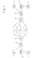
- a telephone 1 either directly or through a telecommunications system PBX 2 connected to a Least Cost Router (LCR) 3.
- LCR Least Cost Router
- the Least cost router 3 is between telecommunications unit 1 or PBX 2 and a local exchange 4 arranged, that is on the "last mile" between local exchanges 4 and TC unit 1.
- the local exchange 4 has access to or is part of a plurality of telecommunications networks T 1 ... T m + 1 .
- the telecommunications networks T i are circuit-switched networks which switch through digital or analog user channel connections for a telecommunications connection.
- it is a matter of digital telecommunication networks which allow a connection to be established and data channels to be switched through in accordance with the ISDN standard.
- the switching center 4 ' On the receiver side, the switching center 4 ', a least cost router 3' and receiver-side telecommunications units 1 'are connected to the telecommunications networks T i , which are connected to the least cost router 3' either directly or via a telecommunications system 2 '.
- Figure 2 shows an alternative arrangement of telecommunications units and telecommunications networks, too the implementation of the invention described below Allow procedure.
- the TK-Unit 1 (again either directly or via a PBX 2) connected to a Least Cost Router 30, which in addition to the function of choosing an inexpensive Telecommunications network or telecommunications provider performs the tasks of a switch, that is the connection of user channel connections and the handling of the associated signaling functions.
- the least cost router 30 is arranged on the network side and in contrast to the arrangement in FIG. 1 that of the TC unit 1 assigned local exchange (not shown) downstream or integrated into this.
- the Least Cost Router 30 belongs to a so-called "minute Seller "who offers TK connections at low cost.
- the least cost router 30 is selected, for example over a certain area code, that of the actual phone number of a called subscriber. This can on the telecommunications unit 1 either automatically or by an appropriate Choose to be done.
- the least cost router 30 in turn has access to a plurality of telecommunications networks T 1 ... T n + 1 or is part of these networks.
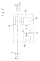
- FIG. 3 shows a router 3, 3 ', 30, 30' according to the invention. It has a control unit 31, a data memory 32, a signaling unit 33 as functional units and a switching matrix 34 as a line switching device.
- the data memory 32 contains routing tables with parameters for a plurality of telecommunications networks T i .
- the parameters relate to the charges of different telecommunication networks depending on the time of day and the destination of a call as well as possibly further price information such as discounts etc.
- the control unit 31 determines, based on the routing tables, which available telecommunications network enables the most cost-effective connection to the called terminal 1 '. In the event that a connection cannot be established via the cheapest telecommunication network T 1 , further telecommunication networks T 2 ... T n + 1 are determined, with decreasing preference.
- the signaling unit 33 is used to process Signaling functions for call control and for establishing a connection. For this purpose, it sends, among other things Control signals the switching matrix 34, which is the connection of user channel connections serves.
- the present embodiment assumes that it the end devices are ISDN devices and accordingly digital data channels (B channels) from switching matrix 34 be switched through.
- the invention is not based on digital user channel connections or the standard ISDN limited.
- the switching network 34 has an input line which starts, for example, from a network termination unit NT 5 to which the calling terminal 1 is connected via an S / T interface. Numerous further input lines from other network termination units, telecommunications systems etc. can be connected to the switching network, but are not shown for the sake of simplicity.
- the switching matrix 34 On the output side, the switching matrix 34 has numerous output lines, via which connections to a called terminal 1 'can be established via various telecommunication networks T 1 ... T n + 1 according to FIGS. 1 and 2.
- the switching network 34 For example, on the input line of the switching network 34 two user data basic channels (B channels) and one signaling channel (D channel) realized according to the ISDN standard.
- the D channel signaling information is via the dashed connection to the control unit 31 and forwarded by this to the signaling unit 33.
- General are connections for signaling / control shown in dashed lines in Figure 3, while those to be switched Data channels (B channels) drawn solid are.
- the signaling unit 33 exchanges signaling information with the called terminal 1 'or this upstream PBXs, local exchanges and switches via a signaling channel 331. If the Least Cost router according to FIG. 1 on the terminal side in front of the local exchange is arranged, so it is Signaling channel around the ISDN D channel, using the signaling information sent to the local exchange become. If the least cost router according to Figure 2 in one Telecommunications network is arranged, it is the signaling channel 331, for example, around a central signaling channel according to the signaling system No. 7, the standard between ISDN exchanges is used.
- signaling between the signaling unit 33 and the called Terminal 1 'or this upstream PBX, local exchanges and switches also as in-band signaling can be done.
- the signaling unit 33 outputs the Signaling information then to the appropriate Data channels of the switching network 34.
- the switching matrix 34 is in the simplest version just a switch matrix, the two B channels on the input side to two B channels on the output side can switch through or switch. There are two B channels available to every ISDN basic access.
- the switching matrix is against it with a variety of input lines and output lines provided, and will be a variety of useful channel connections switched through.
- the calling terminal 1 sends a setup protocol data element as standard via the network termination unit 5.
- the control unit 31 evaluates this setup protocol data element and uses the routing tables stored in the data memory 32 to determine the most cost-effective telecommunications network T 1 for the present connection request.
- telecommunications networks T 2 ,... T n + 1 are determined with descending preference, that is to say increasing costs for the desired connection.
- the signaling unit 33 After selection of telecommunication networks with a specific preference for the present connection request by the control unit 31, the signaling unit 33 first tries to establish a connection to the called terminal via the telecommunication network T 1 with the highest preference (dg the cheapest telecommunication network) (step 101).
- a connection establishment is unsuccessful, for example due to congestion of the network T 1 .
- the signaling unit 33 then tries to establish a connection to the called terminal 1 ′ via the second cheapest network T 2 etc., until a connection is successfully established via a network T n + 1 , n ⁇ 1 (step 102).
- control signals are sent from the signaling unit 33 to the switching matrix 34 for the purpose of connecting the connection from the calling terminal to the called terminal via the network T n + 1 .
- the signaling unit 33 tries to establish a connection via an alternative telecommunications network of higher preference during the existing L7 connection between the calling terminal and the called terminal. For this purpose, an attempt is again first made to establish a connection via the cheapest network T 1 , if this is not possible, via the network T 2 , etc., to the next better network T n (step 103). In a variant of the invention, only an attempt is made to set up an alternative connection via the telecommunications network T 1 .
- a connection can be set up via a telecommunications network T n of higher preference (step 104)
- the telecommunications network used for the L3 data transmission is changed during the existing L7 connection between the calling terminal and the called terminal.
- the signaling unit 33 issues a corresponding control command to the switching network 34, which then switches the connection through via another output line and via the telecommunications network T n now selected (step 105).
- the previous L-3 connection via the telecommunications network of lower preference is cleared after the change, so that no more costs are incurred via this network (step 106).
- steps 103 to 106 are repeated until an L3 connection via the telecommunication network T 1 is present (step 107).
- a change in the telecommunications network also by changing preferences can be triggered.
- a telecommunications provider offers special during the first minute of a connection affordable tariff.
- the corresponding telecommunications network is then the network of highest preference.
- the charges on this network increase, so now another network is the highest preference owns.
- the control unit 31 then sends after the Minute or shortly before, control commands to the signaling unit 33, an alternative connection over the new Network with the highest preference.
- Another example of a change in preferences is a change in fees due to a time zone change. For example, usually change at 6 p.m. the fees of the individual telecommunications networks, so that possibly after 6 p.m. another network the cheapest is before 6 p.m.
- the least cost router 3 is arranged according to FIG in the simplest variant of the invention when changing of the telecommunications network the information to be transmitted available on the other B channel of the two standing B channels switched.
- the transmitted data which are received by the respectively selected telecommunication network, are transmitted to the called terminal 1 'via the switching center, possibly another least cost router and possibly a PBX. It is important that the switch upstream of the called terminal, the upstream switching center or an upstream further least cost router recognize that the data now arriving via the other telecommunications network T n relate to the same L7 connection as that via the previous telecommunications network T n +1 transmitted data, ie the same connection between the calling terminal 1 and the called terminal 1 '.
- This assignment prevents the exchange, the switch or the least cost router from displaying the connection to the called terminal 1 'of the signaling unit 33 as busy, so that no data transmission can take place via the new network.
- This assignment is carried out by means of suitable signaling information which is sent by the signaling unit 33.
- This signaling information contains in particular the sender information of the calling terminal, in particular the parameter "Calling Party Number".
- the least cost router, switch etc. upstream of the called terminal 1 ′ recognizes that the L7 connection is the same.
- the L3 connection is then forwarded or switched through via the new telecommunications network T n to the called terminal 1 'and the previous L3 connection of lower preference is cleared down.
- Signaling information can be on the signaling channel 331 can be sent. It is just as good however, these signaling signals possible as an in-band signal to be sent on a data channel (B channel).
- the switching matrix 34 switches in accordance with the control commands of the signaling unit 33 always the connection to the called TK unit 1 'over the telecommunications network with the highest available preference through.
- the invention is not limited to the above specified embodiments.
- Essential to the invention is alone that a procedure and means are available be made that allow, during an existing L7 connection between a calling and a called Terminal an alternative L3 connection over a Build telecommunications network with cheaper parameters and during the existing L7 connection to this to switch to cheaper telecommunications networks.
Landscapes
- Engineering & Computer Science (AREA)
- Computer Networks & Wireless Communication (AREA)
- Data Exchanges In Wide-Area Networks (AREA)
- Telephonic Communication Services (AREA)
Applications Claiming Priority (2)
| Application Number | Priority Date | Filing Date | Title |
|---|---|---|---|
| DE19907469 | 1999-02-16 | ||
| DE1999107469 DE19907469C2 (de) | 1999-02-16 | 1999-02-16 | Verfahren zur Übertragung von Informationen zwischen einer rufenden TK-Einheit und einer gerufenen TK-Einheit und Router zur Durchführung des Verfahrens |
Publications (3)
| Publication Number | Publication Date |
|---|---|
| EP1033847A2 true EP1033847A2 (fr) | 2000-09-06 |
| EP1033847A3 EP1033847A3 (fr) | 2004-07-14 |
| EP1033847B1 EP1033847B1 (fr) | 2006-04-05 |
Family
ID=7898378
Family Applications (1)
| Application Number | Title | Priority Date | Filing Date |
|---|---|---|---|
| EP20000250036 Expired - Lifetime EP1033847B1 (fr) | 1999-02-16 | 2000-02-08 | Procédé pour le choix d'un réseau de télécommunication pour la transmission d'information entre deux terminaux ainsi qu'un routeur pour la mise en oeuvre |
Country Status (2)
| Country | Link |
|---|---|
| EP (1) | EP1033847B1 (fr) |
| DE (2) | DE19907469C2 (fr) |
Families Citing this family (2)
| Publication number | Priority date | Publication date | Assignee | Title |
|---|---|---|---|---|
| DE10129423A1 (de) * | 2001-06-19 | 2003-01-09 | Tenovis Gmbh & Co Kg | Verfahren zum Aufbau einer Verbindung und Telekommunikationsanlage |
| DE102004027406A1 (de) * | 2004-06-04 | 2006-02-02 | Betty Technology Ag | Vorrichtung und Verfahren zur Übertragung von Daten über eine Telefonleitung |
Family Cites Families (9)
| Publication number | Priority date | Publication date | Assignee | Title |
|---|---|---|---|---|
| DE3420365A1 (de) * | 1984-06-01 | 1985-12-05 | Brown, Boveri & Cie Ag, 6800 Mannheim | Verfahren zur umschaltung zwischen redundanten uebertragungswegen |
| US5046088A (en) * | 1989-10-31 | 1991-09-03 | Dialogic Corporation | Converter for in-band routing and/or origination information |
| US5802502A (en) * | 1993-05-24 | 1998-09-01 | British Telecommunications Public Limited Company | System for selective communication connection based on transaction pricing signals |
| WO1996004758A1 (fr) * | 1994-08-03 | 1996-02-15 | British Telecommunications Public Limited Company | Reseau de telecommunications |
| US5917897A (en) * | 1997-02-24 | 1999-06-29 | Summit Telecom System, Inc. | System and method for controlling a telecommunication network in accordance with economic incentives |
| DE19645368C2 (de) * | 1996-10-07 | 1999-12-30 | Teles Ag | Verfahren und Kommunikationseinrichtung zur Übertragung von Daten in einem Telekommunikationsnetz |
| US5898668A (en) * | 1996-12-13 | 1999-04-27 | Siemens Information And Communication Networks, Inc. | Method and system for increasing quality of service at or below a threshold cost |
| DE19730621A1 (de) * | 1997-07-17 | 1999-01-21 | Alsthom Cge Alcatel | Verfahren zum Übertragen von Daten auf einer ISDN-Anschlußleitung, sowie Leitungsabschlußeinheit, Vermittlungsstelle, Netzabschlußeinheit und Datenendgerät dafür |
| DE19747605C2 (de) * | 1997-10-28 | 1999-11-18 | Deutsche Telekom Ag | Verfahren und Vorrichtung zum Aufbauen wenigstens einer Verbindung mit niedriger Priorität in einem Telekommunikationsnetz |
-
1999
- 1999-02-16 DE DE1999107469 patent/DE19907469C2/de not_active Expired - Fee Related
-
2000
- 2000-02-08 EP EP20000250036 patent/EP1033847B1/fr not_active Expired - Lifetime
- 2000-02-08 DE DE50012505T patent/DE50012505D1/de not_active Expired - Lifetime
Also Published As
| Publication number | Publication date |
|---|---|
| EP1033847B1 (fr) | 2006-04-05 |
| DE19907469A1 (de) | 2000-08-24 |
| EP1033847A3 (fr) | 2004-07-14 |
| DE19907469C2 (de) | 2001-02-01 |
| DE50012505D1 (de) | 2006-05-18 |
Similar Documents
| Publication | Publication Date | Title |
|---|---|---|
| DE2902644C2 (fr) | ||
| EP0731618B1 (fr) | Procédé pour commander un réseau d'accès et central avec un tel réseau d'accès | |
| DE19522988A1 (de) | Verfahren zur Gebühreninformation sowie Dienststeuereinrichtung, Teilnehmervermittlungsstelle, Endgerät und Kommunikationsnetz | |
| DE19859510B4 (de) | Internet-Telefongerät, grossflächiges Datenkommunikationsnetzwerk ausnutzendes Kommunikationssystem und Anschlussadapter | |
| EP1033847B1 (fr) | Procédé pour le choix d'un réseau de télécommunication pour la transmission d'information entre deux terminaux ainsi qu'un routeur pour la mise en oeuvre | |
| EP1097605A2 (fr) | Procede et circuit pour creer des liaisons de signaux de donnees | |
| DE19943742B4 (de) | Verfahren zum Zurverfügungstellen zusätzlicher Dienste an einem Teilnehmeranschluß | |
| DE19747605C2 (de) | Verfahren und Vorrichtung zum Aufbauen wenigstens einer Verbindung mit niedriger Priorität in einem Telekommunikationsnetz | |
| DE4409669C2 (de) | Adapter für den Anschluß mindestens eines analogen Fernsprechendgerätes an ein digitales Telefonnetz | |
| DE19917062C2 (de) | Optimierte Schnittstelle zwischen Zugriffsnetzwerk und Vermittlungseinrichtung | |
| DE19804056A1 (de) | Verfahren zur kostengünstigen Vermittlung von Telekommunikationsverbindungen innerhalb öffentlicher Telekommunikationsnetze | |
| DE19935759B4 (de) | Verfahren und Kommunikationssystem zum Management der Auslastung von Interconnectanschlüssen | |
| DE19844147A1 (de) | Verfahren und Mobil-Kommunikationssystem zur Steuerung eines Kurznachrichtendienstes | |
| DE19964189B4 (de) | Routing-Einrichtung und TK-Einrichtung zum Management der Auslastung von Interconnectanschlüssen | |
| DE19922266C2 (de) | Verfahren und Kommunikationssystem zum Management der Auslastung von Interconnectanschlüssen | |
| WO1999013633A1 (fr) | Telephonie internet | |
| DE29605535U1 (de) | Vorrichtung zur Mehrfachnutzung einer Übertragungsleitung | |
| DE19621716A1 (de) | Verfahren zum Aufbau einer Verbindung sowie Vermittlungsstelle, Dienstrechner und Kommunikationsnetz | |
| DE19844672B4 (de) | Programmgesteuertes Kommunikationssystem zur Vermittlung von daran angeschlossenen analogen und digitalen Kommunikationsendgeräten | |
| EP1138169B1 (fr) | Systeme de telecommunication et procede pour la transmission de donnees | |
| EP1216583A1 (fr) | Procede et dispositif de commutation d'une liaison dans un reseau de communication | |
| EP1014634A1 (fr) | Procédé et dispositif pour l'établissement de connections d'un terminal sur un premier réseau vers un point d'accès d'un deuxième réseau | |
| DE19829421A1 (de) | Verfahren zur Übertragung von Audio- und/oder Videodaten zwischen Telekommunikationsendgeräten | |
| WO1998056189A2 (fr) | Procede et installation de traitement de donnees pour commutation dans un systeme de telecommunication | |
| EP0883321A2 (fr) | Procédé pour le transport de données électroniques trans-network |
Legal Events
| Date | Code | Title | Description |
|---|---|---|---|
| PUAI | Public reference made under article 153(3) epc to a published international application that has entered the european phase |
Free format text: ORIGINAL CODE: 0009012 |
|
| AK | Designated contracting states |
Kind code of ref document: A2 Designated state(s): AT BE CH CY DE DK ES FI FR GB GR IE IT LI LU MC NL PT SE |
|
| AX | Request for extension of the european patent |
Free format text: AL;LT;LV;MK;RO;SI |
|
| PUAL | Search report despatched |
Free format text: ORIGINAL CODE: 0009013 |
|
| AK | Designated contracting states |
Kind code of ref document: A3 Designated state(s): AT BE CH CY DE DK ES FI FR GB GR IE IT LI LU MC NL PT SE |
|
| AX | Request for extension of the european patent |
Extension state: AL LT LV MK RO SI |
|
| RIC1 | Information provided on ipc code assigned before grant |
Ipc: 7H 04Q 3/66 A Ipc: 7H 04Q 11/04 B Ipc: 7H 04L 12/28 B |
|
| 17P | Request for examination filed |
Effective date: 20040902 |
|
| 17Q | First examination report despatched |
Effective date: 20041122 |
|
| AKX | Designation fees paid |
Designated state(s): DE FR GB IT |
|
| GRAP | Despatch of communication of intention to grant a patent |
Free format text: ORIGINAL CODE: EPIDOSNIGR1 |
|
| RIC1 | Information provided on ipc code assigned before grant |
Ipc: 7H 04L 12/28 B Ipc: 7H 04Q 11/04 B Ipc: 7H 04Q 3/66 B Ipc: 7H 04L 12/56 A |
|
| GRAS | Grant fee paid |
Free format text: ORIGINAL CODE: EPIDOSNIGR3 |
|
| GRAA | (expected) grant |
Free format text: ORIGINAL CODE: 0009210 |
|
| AK | Designated contracting states |
Kind code of ref document: B1 Designated state(s): DE FR GB IT |
|
| PG25 | Lapsed in a contracting state [announced via postgrant information from national office to epo] |
Ref country code: IT Free format text: LAPSE BECAUSE OF FAILURE TO SUBMIT A TRANSLATION OF THE DESCRIPTION OR TO PAY THE FEE WITHIN THE PRESCRIBED TIME-LIMIT;WARNING: LAPSES OF ITALIAN PATENTS WITH EFFECTIVE DATE BEFORE 2007 MAY HAVE OCCURRED AT ANY TIME BEFORE 2007. THE CORRECT EFFECTIVE DATE MAY BE DIFFERENT FROM THE ONE RECORDED. Effective date: 20060405 Ref country code: GB Free format text: LAPSE BECAUSE OF FAILURE TO SUBMIT A TRANSLATION OF THE DESCRIPTION OR TO PAY THE FEE WITHIN THE PRESCRIBED TIME-LIMIT Effective date: 20060405 |
|
| REG | Reference to a national code |
Ref country code: GB Ref legal event code: FG4D Free format text: NOT ENGLISH |
|
| REF | Corresponds to: |
Ref document number: 50012505 Country of ref document: DE Date of ref document: 20060518 Kind code of ref document: P |
|
| GBV | Gb: ep patent (uk) treated as always having been void in accordance with gb section 77(7)/1977 [no translation filed] |
Effective date: 20060405 |
|
| ET | Fr: translation filed | ||
| PLBE | No opposition filed within time limit |
Free format text: ORIGINAL CODE: 0009261 |
|
| STAA | Information on the status of an ep patent application or granted ep patent |
Free format text: STATUS: NO OPPOSITION FILED WITHIN TIME LIMIT |
|
| 26N | No opposition filed |
Effective date: 20070108 |
|
| REG | Reference to a national code |
Ref country code: FR Ref legal event code: PLFP Year of fee payment: 16 |
|
| PGFP | Annual fee paid to national office [announced via postgrant information from national office to epo] |
Ref country code: IT Payment date: 20150224 Year of fee payment: 16 |
|
| REG | Reference to a national code |
Ref country code: FR Ref legal event code: PLFP Year of fee payment: 17 |
|
| PGFP | Annual fee paid to national office [announced via postgrant information from national office to epo] |
Ref country code: DE Payment date: 20160729 Year of fee payment: 17 |
|
| PGFP | Annual fee paid to national office [announced via postgrant information from national office to epo] |
Ref country code: FR Payment date: 20160729 Year of fee payment: 17 |
|
| PG25 | Lapsed in a contracting state [announced via postgrant information from national office to epo] |
Ref country code: IT Free format text: LAPSE BECAUSE OF NON-PAYMENT OF DUE FEES Effective date: 20160208 |
|
| REG | Reference to a national code |
Ref country code: DE Ref legal event code: R119 Ref document number: 50012505 Country of ref document: DE |
|
| REG | Reference to a national code |
Ref country code: FR Ref legal event code: ST Effective date: 20171031 |
|
| PG25 | Lapsed in a contracting state [announced via postgrant information from national office to epo] |
Ref country code: DE Free format text: LAPSE BECAUSE OF NON-PAYMENT OF DUE FEES Effective date: 20170901 Ref country code: FR Free format text: LAPSE BECAUSE OF NON-PAYMENT OF DUE FEES Effective date: 20170228 |