EP1033907A2 - Schaltungsanordnung zum Betrieb mindestens einer Hochdruckentladungslampe und Betriebsverfahren - Google Patents
Schaltungsanordnung zum Betrieb mindestens einer Hochdruckentladungslampe und Betriebsverfahren Download PDFInfo
- Publication number
- EP1033907A2 EP1033907A2 EP00103513A EP00103513A EP1033907A2 EP 1033907 A2 EP1033907 A2 EP 1033907A2 EP 00103513 A EP00103513 A EP 00103513A EP 00103513 A EP00103513 A EP 00103513A EP 1033907 A2 EP1033907 A2 EP 1033907A2
- Authority
- EP
- European Patent Office
- Prior art keywords
- voltage
- pressure discharge
- discharge lamp
- circuit arrangement
- circuit
- Prior art date
- Legal status (The legal status is an assumption and is not a legal conclusion. Google has not performed a legal analysis and makes no representation as to the accuracy of the status listed.)
- Withdrawn
Links
- 238000000034 method Methods 0.000 title claims description 6
- 239000003990 capacitor Substances 0.000 claims abstract description 54
- 230000008878 coupling Effects 0.000 claims abstract description 33
- 238000010168 coupling process Methods 0.000 claims abstract description 33
- 238000005859 coupling reaction Methods 0.000 claims abstract description 33
- 238000004804 winding Methods 0.000 claims description 21
- 230000002457 bidirectional effect Effects 0.000 claims description 3
- 230000001939 inductive effect Effects 0.000 claims 1
- 230000005669 field effect Effects 0.000 description 7
- 238000011017 operating method Methods 0.000 description 3
- 239000000654 additive Substances 0.000 description 2
- 230000000996 additive effect Effects 0.000 description 2
- 230000015572 biosynthetic process Effects 0.000 description 2
- 238000010586 diagram Methods 0.000 description 2
- 230000006698 induction Effects 0.000 description 2
- 230000006641 stabilisation Effects 0.000 description 2
- 238000011105 stabilization Methods 0.000 description 2
- 230000005540 biological transmission Effects 0.000 description 1
- 238000010891 electric arc Methods 0.000 description 1
- 229910001507 metal halide Inorganic materials 0.000 description 1
- 150000005309 metal halides Chemical class 0.000 description 1
Images


Classifications
-
- H—ELECTRICITY
- H05—ELECTRIC TECHNIQUES NOT OTHERWISE PROVIDED FOR
- H05B—ELECTRIC HEATING; ELECTRIC LIGHT SOURCES NOT OTHERWISE PROVIDED FOR; CIRCUIT ARRANGEMENTS FOR ELECTRIC LIGHT SOURCES, IN GENERAL
- H05B41/00—Circuit arrangements or apparatus for igniting or operating discharge lamps
- H05B41/14—Circuit arrangements
- H05B41/36—Controlling
- H05B41/38—Controlling the intensity of light
- H05B41/382—Controlling the intensity of light during the transitional start-up phase
- H05B41/388—Controlling the intensity of light during the transitional start-up phase for a transition from glow to arc
-
- H—ELECTRICITY
- H05—ELECTRIC TECHNIQUES NOT OTHERWISE PROVIDED FOR
- H05B—ELECTRIC HEATING; ELECTRIC LIGHT SOURCES NOT OTHERWISE PROVIDED FOR; CIRCUIT ARRANGEMENTS FOR ELECTRIC LIGHT SOURCES, IN GENERAL
- H05B41/00—Circuit arrangements or apparatus for igniting or operating discharge lamps
- H05B41/14—Circuit arrangements
-
- H—ELECTRICITY
- H05—ELECTRIC TECHNIQUES NOT OTHERWISE PROVIDED FOR
- H05B—ELECTRIC HEATING; ELECTRIC LIGHT SOURCES NOT OTHERWISE PROVIDED FOR; CIRCUIT ARRANGEMENTS FOR ELECTRIC LIGHT SOURCES, IN GENERAL
- H05B41/00—Circuit arrangements or apparatus for igniting or operating discharge lamps
- H05B41/14—Circuit arrangements
- H05B41/26—Circuit arrangements in which the lamp is fed by power derived from DC by means of a converter, e.g. by high-voltage DC
- H05B41/28—Circuit arrangements in which the lamp is fed by power derived from DC by means of a converter, e.g. by high-voltage DC using static converters
- H05B41/288—Circuit arrangements in which the lamp is fed by power derived from DC by means of a converter, e.g. by high-voltage DC using static converters with semiconductor devices and specially adapted for lamps without preheating electrodes, e.g. for high-intensity discharge lamps, high-pressure mercury or sodium lamps or low-pressure sodium lamps
- H05B41/2881—Load circuits; Control thereof
-
- Y—GENERAL TAGGING OF NEW TECHNOLOGICAL DEVELOPMENTS; GENERAL TAGGING OF CROSS-SECTIONAL TECHNOLOGIES SPANNING OVER SEVERAL SECTIONS OF THE IPC; TECHNICAL SUBJECTS COVERED BY FORMER USPC CROSS-REFERENCE ART COLLECTIONS [XRACs] AND DIGESTS
- Y02—TECHNOLOGIES OR APPLICATIONS FOR MITIGATION OR ADAPTATION AGAINST CLIMATE CHANGE
- Y02B—CLIMATE CHANGE MITIGATION TECHNOLOGIES RELATED TO BUILDINGS, e.g. HOUSING, HOUSE APPLIANCES OR RELATED END-USER APPLICATIONS
- Y02B20/00—Energy efficient lighting technologies, e.g. halogen lamps or gas discharge lamps
-
- Y—GENERAL TAGGING OF NEW TECHNOLOGICAL DEVELOPMENTS; GENERAL TAGGING OF CROSS-SECTIONAL TECHNOLOGIES SPANNING OVER SEVERAL SECTIONS OF THE IPC; TECHNICAL SUBJECTS COVERED BY FORMER USPC CROSS-REFERENCE ART COLLECTIONS [XRACs] AND DIGESTS
- Y10—TECHNICAL SUBJECTS COVERED BY FORMER USPC
- Y10S—TECHNICAL SUBJECTS COVERED BY FORMER USPC CROSS-REFERENCE ART COLLECTIONS [XRACs] AND DIGESTS
- Y10S315/00—Electric lamp and discharge devices: systems
- Y10S315/05—Starting and operating circuit for fluorescent lamp
Definitions
- the invention relates to a circuit arrangement for operating at least one High-pressure discharge lamp according to the preamble of claim 1 and a Operating method for a high pressure discharge lamp.
- Such a circuit arrangement is, for example, in the international patent application with publication number WO 98/18297.
- This Laid-open specification describes a circuit arrangement for high-frequency operation a high-pressure discharge lamp, that is, for operating the high-pressure discharge lamp on an AC voltage with a frequency above 200 kHz and preferably even above 500 kHz.
- the circuit arrangement has a voltage converter which has a high-frequency AC voltage at its output generated.
- the output of this voltage converter is from the two secondary windings of a transformer.
- the first secondary winding is in one designed as a series resonance circuit, provided with the lamp connections load circuit switched while the second secondary winding to the voltage input an ignition device is connected.
- the ignition device is around a pulse ignition device, which the high pressure discharge lamp by means of a Auxiliary electrode during the ignition phase with unipolar high-voltage pulses acted upon.
- a pulse ignition device which the high pressure discharge lamp by means of a Auxiliary electrode during the ignition phase with unipolar high-voltage pulses acted upon.
- the circuit arrangement according to the invention has a voltage converter for generation a high-frequency AC voltage at its AC voltage output, a load circuit connected to the AC voltage output, the at least one lamp inductor, a coupling capacitor and connections for at least has a high-pressure discharge lamp, and an ignition device for Igniting a gas discharge in the at least one high-pressure discharge lamp, the ignition device having a high voltage source and a high voltage DC voltage output is provided.
- the coupling capacitor is over a charging resistor connected to the high-voltage DC voltage output.
- the coupling capacitor is located in the at least one high-pressure discharge lamp via the electrically conductive discharge path in the at least one high-pressure discharge lamp unload.
- the one on the at least one high-pressure discharge lamp flowing discharge current of the coupling capacitor contributes significantly Formation and stabilization of the discharge arc in the at least one high-pressure discharge lamp at.
- the shortened by the at least one High-pressure discharge lamp flowing discharge current of the coupling capacitor Transitional period from the undesired glow discharge that damages the lamp electrodes for arc discharge.
- the high voltage source of the ignition device is advantageously in the form of a cascade connection for voltage multiplication of the output voltage of the voltage converter or as a secondary winding inductively coupled to the lamp choke possibly with a downstream cascade connection for voltage multiplication educated.
- To destroy the voltage converter due to excessive Preventing ignition voltages is advantageously parallel to the AC voltage output a voltage-limiting component of the voltage converter.
- Volts are considered voltage-limiting components because they have high electrical outputs are resilient, advantageously bidirectional diodes, for example Transil diodes, or varistors used.
- the load circuit of the voltage converter advantageously also has a resonance capacitor which forms a series resonance circuit with the lamp choke.
- the method of increasing the resonance can also be made available the discharge arc takeover energy and to generate the operating voltage for which at least one high-pressure discharge lamp can be used.
- the resonance capacitor is parallel to that of the coupling capacitor and the at least one high-pressure discharge lamp existing series connection. This will cause the ignition voltage for the at least one high-pressure discharge lamp from the additive superimposition the high-voltage DC voltage present at the coupling capacitor and the high-frequency alternating voltage present at the resonance capacitor of the voltage converter formed.
- the voltage converter is advantageously a single-ended converter or a push-pull converter, for example as a push-pull inverter.
- This voltage converter are particularly suitable for a comparatively low DC voltage of 12 V or 24 V, for example, which is common in motor vehicles, into a high-frequency AC voltage with an amplitude of approximately 500 V and one Convert frequency of more than 500 kHz.
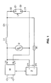
- FIG. 1 shows a block diagram of the circuit arrangement according to the invention. It has a voltage converter W, which is fed by a voltage source and at its AC voltage output j10, j11 a high-frequency AC voltage for high-frequency operation of a high-pressure discharge lamp LP. On the AC voltage output j10, j11 of the voltage converter W is a load circuit connected, a lamp inductor L1, a coupling capacitor C1, two connections j12, j13 for a high-pressure discharge lamp LP and a bidirectional Diode circuit D, for example from two series connected, in opposite directions polarized Zener diodes or consists of a transile diode D.
- a voltage converter W which is fed by a voltage source and at its AC voltage output j10, j11 a high-frequency AC voltage for high-frequency operation of a high-pressure discharge lamp LP.
- a lamp inductor L1 On the AC voltage output j10, j11 of the voltage converter W is a load circuit connected,
- High-pressure discharge lamp When connected High-pressure discharge lamp are the two connections j12, j13, respectively connected to a lamp electrode E1 or E2. Then the lamp choke L1, the coupling capacitor C1 and the discharge gap between the lamp electrodes E1, E2 connected in series.
- the transile diode D is parallel to the AC voltage output j10, j11 arranged.
- the circuit arrangement shown in Figure 1 also has an ignition device Z, which is a high voltage source and a high voltage DC output j14, j15.
- the high-voltage DC voltage output j14, j15 is via a charging resistor R1 to the one consisting of the lamp choke L1 and the coupling capacitor C1 Series connection L1, C1 connected.
- this is the positive one Connection j14 of the high-voltage DC voltage output with connection j10 of the AC voltage output of the voltage converter W, with the lamp choke L1 and connected to the transile diode D.
- the negative terminal j15 of the high-voltage DC voltage output is about the charging resistor R1 with the coupling capacitor C1 and connected to the lamp connector j12.
- the second lamp connector j13 is with the j11 connection of the AC voltage output and with the transile diode connected.
- the coupling capacitor has a capacitance of 1.1 nF and Inductance of the lamp choke is 45 ⁇ H.
- the voltage converter W generates the voltage applied to its voltage input Low voltage DC voltage of, for example, 12 V or 24 V or 42 V a high-frequency AC voltage with an amplitude of approximately 500 V and one Frequency above 500 kHz and provides this at its AC voltage output j10, j11 ready to operate the high-pressure discharge lamp LP.
- This AC voltage However, it is not sufficient to discharge the gas in the high-pressure discharge lamp To ignite LP.
- the to the AC voltage output j10, j11 des Voltage transformer W connected load circuit is therefore initially between the two lamp electrodes E1, E2 interrupted.
- the ignition device Z generates their high-voltage DC voltage output j 14, j15 one for igniting the gas discharge sufficient DC voltage of up to in the high-pressure discharge lamp LP 25 kV.
- the coupling capacitor C1 is connected via the charging resistor R1 and via the Lamp inductor L1 to the high-voltage DC voltage generated by the ignition device Z. charged. It serves as a high voltage source during the ignition phase for the load circuit and in particular for the high-pressure discharge lamp LP. After the gas discharge has been ignited in the high-pressure discharge lamp LP the discharge path between the two lamp electrodes E1, E2 becomes electrical conductive.
- the coupling capacitor C1 discharges through the now conductive discharge path the high pressure discharge lamp LP and thereby contributes to training and to stabilize a discharge arc between the lamp electrodes E1, E2 and to shorten the start-up phase of the high-pressure discharge lamp LP.
- the load circuit is no longer after the gas discharge has ignited interrupted, so that now the high frequency generated by the voltage converter W.
- AC voltage a high-frequency alternating current over the discharge path E1-E2 of the high-pressure discharge lamp LP can flow.
- the transile diode D serves as Overvoltage protection for the voltage converter W. Exceeds the voltage drop on the coupling capacitor C1 a critical, determined by the transile diode D. Threshold value, the transile diode D becomes conductive and the coupling capacitor C1 discharges primarily via the transile diode D instead of via the discharge path E1-E2 of the high-pressure discharge lamp LP.
- FIG. 2 shows a block diagram of the circuit arrangement according to the invention with a load circuit designed as a series resonance circuit.
- This circuit arrangement only differs from the circuit arrangement shown in FIG. 1 by an additional resonance capacitor C2, which is connected to the lamp inductor L1 forms a series resonance circuit and which exists parallel to the series connection switched from the coupling capacitor C1 and the high-pressure discharge lamp LP is.
- the capacitance of the resonance capacitor C2 is 80 pF. Because of the additional Resonant capacitor C2 differs in the operating method of the high-pressure discharge lamp LP on the circuit arrangement according to Figure 2 slightly of the operating method of the high-pressure discharge lamp LP on the circuit arrangement according to Figure 1.
- the voltage converter W on his AC voltage output j10, j11 provides a high-frequency AC voltage, flows through the load circuit designed as a series resonance circuit, that is, a high frequency via the lamp choke L1 and the resonance capacitor C2 Alternating current.
- the load circuit designed as a series resonance circuit that is, a high frequency via the lamp choke L1 and the resonance capacitor C2 Alternating current.
- the ignition device Z For igniting the gas discharge in the high-pressure discharge lamp LP generates the ignition device Z at its DC voltage output j14, 15 High-voltage DC voltage and charges the coupling capacitor C1 via the charging resistor R1 to a high-voltage DC voltage of up to 25 kV.
- the Both the coupling capacitor C1 and the resonance capacitor serve for the ignition phase C2 of the high-pressure discharge lamp LP as a voltage source.
- the voltage converter W preferably operated in such a way that it generates a high-frequency AC voltage, whose frequency is close to the resonance frequency of the series resonance circuit.
- a resonance-exaggerated high frequency becomes at the resonance capacitor C2 AC voltage generates both the formation and stabilization of a discharge arc in the high pressure discharge lamp LP also improves the start-up phase the high-pressure discharge lamp LP - this is the operating phase immediately after ignition of the gas discharge, during which the ionizable, for light emission evaporate contributing filling components of the high pressure discharge lamp - shortened.
- the coupling capacitor C1 becomes LP over the now conductive discharge path Discharge lamp E1-E2.
- the voltage converter W becomes such controlled that it has a high frequency at its AC voltage output j10, j11 AC voltage generated, the frequency of which is a sufficient distance from Has resonance frequency of the series resonance circuit, so that at the lamp choke L1 and the resonance capacitor C2 no longer shows an increase in resonance.
- the Transil diode D also serves to protect the voltage converter W from a Voltage overload due to the on the coupling capacitor C1 or on the resonance capacitor C2 voltages present during the ignition phase.
- FIGS. 3 and 4 are two different versions of the ignition device Z is shown, for both of the exemplary embodiments shown in FIGS. 1 and 2 the circuit arrangement according to the invention, that is to say for a load circuit without and with resonance capacitor C2, can be used. Therefore in the Figures 3 and 4 of the resonance capacitor C2 each shown in dashed lines.
- the Ignition device Z according to FIG. 3 consists of an inductively connected to the lamp choke L1 coupled secondary winding L2, one connected in series to the secondary winding L2 Rectifier diode D1 and one in parallel to the series connection of secondary winding L2 and rectifier diode D1 arranged capacitor C3.
- the secondary winding L2 serves as a high voltage source for the ignition device Z.
- At Switching on the voltage converter W becomes a high voltage in the secondary winding L2 induced and rectified by the diode D1. This rectified High voltage is applied to the coupling capacitor C1 via the resistor R1, as already explained above, supplied.
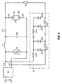
- the ignition device Z is designed as a cascade circuit for multiplying the voltage of the AC voltage provided by the voltage converter W at its AC voltage output j10, j11.
- the cascade circuit has, for example, 20 stages, of which only the first and the last one are shown in FIG. 4 in order to convert the 500 V AC voltage of the voltage converter W into a 20 kV DC voltage.
- the voltage input of the cascade circuit is connected to the AC voltage output j10, j11 of the voltage converter W.
- the high-voltage output of the cascade circuit is connected to the coupling capacitor C1 and to the lamp connection j12 via the charging resistor R1.
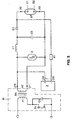
- the voltage converter W of the second embodiment designed as a resonant single-ended converter.
- the single-ended converter W points a field effect transistor T1, a transformer TR with a primary winding n1 and a secondary winding n2 and a control device (not shown) for the field effect transistor T1 and a capacitor C4.
- the primary winding n1 and the drain-source path of the field effect transistor T1 are connected in series.
- the secondary winding n2 of the transformer TR is connected to the connections j10, j11 of the AC voltage output of the single-ended converter W. she serves the load circuit as a high-frequency AC voltage source.
- the gate electrode of the Field effect transistor T1 is connected to the control device.
- the condenser C4 is arranged parallel to the drain-source path of the field effect transistor T1.
- the switching clock of the field effect transistor T1 determines the frequency of the Secondary winding generated induction voltage.
- the field effect transistor T1 controlled by the control device such that the frequency close to the induction voltage generated on the secondary winding n2 the resonance frequency of the series resonance circuit C2, L1. This occurs at the Resonance circuit components L1 and C2 during the aforementioned operating phases resonant excessive high-frequency AC voltage.
- the resonance frequency of the Series resonance circuit L1, C2 is according to the dimensioning mentioned above of these components is approximately 2.653 MHz.
- the high-pressure discharge lamp LP At the end of the ignition phase and the start-up phase the high-pressure discharge lamp LP with a high-frequency AC voltage operated at approximately 1 MHz. To the occurrence of acoustic resonances To avoid in the discharge plasma, this operating frequency modulated a frequency of 100 kHz so that the frequency of the lamp voltage 0.9 MHz to 1.1 MHz. The operating voltage of the high pressure discharge lamp LP is approx. 80 V after the start-up phase.
- the high-pressure discharge lamp LP is a metal halide high-pressure discharge lamp with an electrical power consumption of about 35 watts in a motor vehicle headlight at the vehicle electrical system voltage the motor vehicle is operated.
- Table 1 gives a suitable dimensioning of the circuit components.
- a push-pull converter for example, a push-pull inverter, whose AC voltage output formed by the secondary winding of a transformer becomes.
Landscapes
- Circuit Arrangements For Discharge Lamps (AREA)
Abstract
Description
- Figur 1
- eine schematische Darstellung des ersten Ausführungsbeispiels der erfindungsgemäßen Schaltungsanordnung
- Figur 2
- eine schematische Darstellung des zweiten Ausführungsbeispiels der erfindungsgemäßen Schaltungsanordnung mit einem als Serienresonanzkreis ausgebildeten Lastkreis
- Figur 3
- die Schaltungsanordnung gemäß Figur 1 oder 2 mit einer Zündvorrichtung, die eine Sekundärwicklung über der Lampendrossel aufweist, in schematischer Darstellung
- Figur 4
- die Schaltungsanordnung gemäß Figur 1 oder 2 mit einer Zündvorrichtung, die eine Kaskadenschaltung zur Spannungsvervielfachung aufweist, in schematischer Darstellung
- Figur 5
- die Schaltungsanordnung gemäß Figur 2 mit einem als resonant arbeitenden Eintaktwandler ausgebildeten Spannungswandler in schematischer Darstellung

Claims (14)
- Schaltungsanordnung zum Betrieb mindestens einer Hochdruckentladungslampe mit einer hochfrequenten Wechselspannung, wobei die Schaltungsanordnung folgende Merkmale aufweist:dadurch gekennzeichnet, daß der Koppelkondensator (C1) über einen Ladewiderstand (R1) mit dem Hochvolt-Gleichspannungsausgang (j14, j15) verbunden ist.einen Spannungswandler (W) mit einem Wechselspannungsausgang (j10, j11),einen an den Wechselspannungsausgang (j10, j11) angeschlossenen Lastkreis, der zumindest eine Lampendrossel (L1), einen Koppelkondensator (C1) und Anschlüsse für mindestens eine Hochdruckentladungslampe (LP) aufweist,eine Zündvorrichtung (Z) mit einer Hochspannungsquelle und einem Hochvolt-Gleichspannungsausgang (j14, j15) zum Zünden einer Gasentladung in der mindestens einen Hochdruckentladungslampe (LP),
- Schaltungsanordnung nach Anspruch 1, dadurch gekennzeichnet, daß die Schaltungsanordnung eine Schaltungsanordnung zum Hochfrequenzbetrieb der mindestens einen Hochdruckentladungslampe (LP) mit Wechselspannungsfrequenzen oberhalb von 500 KHz ist.
- Schaltungsanordnung nach Anspruch 1, dadurch gekennzeichnet, daß die Hochspannungsquelle als eine Kaskadenschaltung zur Spannungsvervielfachung ausgebildet ist.
- Schaltungsanordnung nach Anspruch 1, dadurch gekennzeichnet, daß die Hochspannungsquelle als induktiv an die Lampendrossel (L1) gekoppelte Sekundärwicklung (L2) ausgebildet ist.
- Schaltungsanordnung nach Anspruch 4, dadurch gekennzeichnet, daß die Zündvorrichtung (Z) eine in Serie zur Sekundärwicklung (L2) geschaltete Gleichrichterdiode (D1) und einen parallel zu der aus der Sekundärwicklung (L2) und der Gleichrichterdiode (D1) bestehenden Serienschaltung angeordneten Kondensator (C3) aufweist.
- Schaltungsanordnung nach Anspruch 1, dadurch gekennzeichnet, daß der Lastkreis zusätzlich zumindest einen Resonanzkondensator (C2) besitzt, der mit der Lampendrossel (L1) einen Serienresonanzkreis bildet.
- Schaltungsanordnung nach Anspruch 6, dadurch gekennzeichnet, daß der Resonanzkondensator (C2) parallel zu der aus dem Koppelkondensator (C1) und der mindestens einen Hochdruckentladungslampe (LP) bestehenden Serienschaltung geschaltet ist.
- Schaltungsanordnung nach Anspruch 1, dadurch gekennzeichnet, daß parallel zum Wechselspannungsausgang (j10, j11) des Spannungswandlers (W) zumindest ein spannungsbegrenzendes Bauteil (D) geschaltet ist.
- Schaltungsanordnung nach Anspruch 8, dadurch gekennzeichnet, daß das spannungsbegrenzende Bauteil eine bidirektionale Diode (D) oder ein Varistor ist.
- Schaltungsanordnung nach Anspruch 1, dadurch gekennzeichnet, daß der Spannungswandler (W) als Eintaktwandler ausgebildet ist.
- Schaltungsanordnung nach Anspruch 1, dadurch gekennzeichnet, daß der Spannungswandler (W) als Gegentaktwandler ausgebildet ist.
- Verfahren zum Betrieb einer Hochdruckentladungslampe an einer Schaltungsanordnung gemäß Anspruch 1, wobeidadurch gekennzeichnet, daß die von der Zündvorrichtung (Z) erzeugte Hochspannung dem Koppelkondensator (C1) zugeführt wird und der Koppelkondensator (C1) während der Zündphase als Spannungsquelle für die mindestens eine Hochdruckentladungslampe (LP) dient.die Zündvorrichtung (Z) während der Zündphase eine Hochspannung zum Zünden einer Gasentladung in der mindestens einen Hochdruckentladungslampe (LP) erzeugt,der Spannungswandler (W) an seinem Wechselspannungsausgang (j10, j11) eine zur Aufrechterhaltung der Gasentladung in der Hochdruckentladungslampe (LP) ausreichende hochfrequente Wechselspannung generiert,
- Verfahren nach Anspruch 12, dadurch gekennzeichnet, daß der Spannungswandler (W) eine hochfrequente Wechselspannung von mindestens 500 kHz erzeugt.
- Verfahren zum Betrieb einer Hochdruckentladungslampe nach Anspruch 12 an einer Schaltungsanordnung gemäß Anspruch 6, dadurch gekennzeichnet, daß der Spannungswandler (W) zumindest während der Zündphase der Hochdruckentladungslampe (LP) an seinem Wechselspannungsausgang (j10, j11) eine derartige hochfrequente Wechselspannung erzeugt, daß am Resonanzkondensator (C2) ein resonanzüberhöhter Spannungsabfall generiert wird, wobei der mindestens einen Hochdruckentladungslampe (LP) zum Zünden einer Gasentladung sowohl die resonanzüberhöhte Spannung des Resonanzkondensators (C2) als auch die Hochvolt-Gleichspannung des Koppel-kondensators (C1) zugeführt werden.
Applications Claiming Priority (2)
| Application Number | Priority Date | Filing Date | Title |
|---|---|---|---|
| DE19909530A DE19909530A1 (de) | 1999-03-04 | 1999-03-04 | Schaltungsanordnung zum Betrieb mindestens einer Hochdruckentladungslampe und Betriebsverfahren |
| DE19909530 | 1999-03-04 |
Publications (2)
| Publication Number | Publication Date |
|---|---|
| EP1033907A2 true EP1033907A2 (de) | 2000-09-06 |
| EP1033907A3 EP1033907A3 (de) | 2001-12-19 |
Family
ID=7899708
Family Applications (1)
| Application Number | Title | Priority Date | Filing Date |
|---|---|---|---|
| EP00103513A Withdrawn EP1033907A3 (de) | 1999-03-04 | 2000-02-18 | Schaltungsanordnung zum Betrieb mindestens einer Hochdruckentladungslampe und Betriebsverfahren |
Country Status (7)
| Country | Link |
|---|---|
| US (1) | US6194844B1 (de) |
| EP (1) | EP1033907A3 (de) |
| JP (1) | JP2000260587A (de) |
| KR (1) | KR20010006732A (de) |
| CA (1) | CA2299862C (de) |
| DE (1) | DE19909530A1 (de) |
| HU (1) | HUP0000993A3 (de) |
Families Citing this family (13)
| Publication number | Priority date | Publication date | Assignee | Title |
|---|---|---|---|---|
| DE19823641A1 (de) * | 1998-05-27 | 2000-02-10 | Bosch Gmbh Robert | Zünder für eine Gasentladungslampe, insbesondere Hochdruck-Gasentladungslampe für Kraftfahrzeugscheinwerfer |
| DE10100037A1 (de) * | 2001-01-03 | 2002-07-04 | Patent Treuhand Ges Fuer Elektrische Gluehlampen Mbh | Schaltungsanordnung zum Betrieb von elektrischen Lampen |
| JP2004522288A (ja) * | 2001-07-19 | 2004-07-22 | コーニンクレッカ フィリップス エレクトロニクス エヌ ヴィ | Hidランプ安定器の過電圧保護 |
| DE10333729A1 (de) * | 2003-07-23 | 2005-03-10 | Patent Treuhand Ges Fuer Elektrische Gluehlampen Mbh | Vorschaltgerät für mindestens eine Hochdruckentladungslampe, Betriebsverfahren und Beleuchtungssytem für eine Hochdruckentladungslampe |
| US7221103B2 (en) * | 2003-07-23 | 2007-05-22 | Patent-Treuhand-Gesellschaft Fur Elektrische Gluhlampen Mbh | Circuit for operating high-pressure discharge lamps |
| DE10337378B4 (de) * | 2003-08-13 | 2017-11-16 | Xylem Ip Holdings Llc | Elektronisches Vorschaltgerät |
| DE102004020499A1 (de) | 2004-04-26 | 2005-11-10 | Patent-Treuhand-Gesellschaft für elektrische Glühlampen mbH | Schaltungsanordnung zum Betrieb von Hochdruckentladungslampen und Betriebsverfahren für eine Hochdruckentladungslampe |
| DE502006007109D1 (de) * | 2005-04-14 | 2010-07-15 | Osram Gmbh | Vorrichtung und verfahren zum betreiben einer hochdruckentladungslampe |
| EP1869954A1 (de) * | 2005-04-14 | 2007-12-26 | Patent-Treuhand-Gesellschaft für elektrische Glühlampen mbH | Vorrichtung zum betreiben oder zünden einer hochdruckentladungslampe, lampensockel und beleuchtungssystem mit einer derartigen vorrichtung sowie verfahren zum betreiben einer hochdruckentladungslampe |
| US8652286B2 (en) * | 2009-01-09 | 2014-02-18 | Reebok International Limited | Stretchable applique and method for making the same |
| DE102011076333A1 (de) | 2011-05-24 | 2012-11-29 | Osram Ag | Schaltungsanordnung und Verfahren zum Betreiben mindestens einer Hochdruckentladungslampe |
| CN102291916A (zh) * | 2011-07-25 | 2011-12-21 | 德清县伊科爱能电子科技有限公司 | 一种路灯灯管寿命监控系统 |
| DE102011087703A1 (de) | 2011-12-05 | 2013-06-06 | Osram Gmbh | Schaltungsanordnung zum Zünden und Betrieb einer Entladungslampe |
Family Cites Families (12)
| Publication number | Priority date | Publication date | Assignee | Title |
|---|---|---|---|---|
| JPS6016080B2 (ja) * | 1980-08-20 | 1985-04-23 | ウシオ電機株式会社 | 直流放電灯点灯装置 |
| NL8600813A (nl) * | 1986-03-28 | 1987-10-16 | Philips Nv | Schakelinrichting voor het bedrijven van een hogedrukontladingslamp. |
| NL8701358A (nl) * | 1987-06-11 | 1989-01-02 | Philips Nv | Schakelinrichting. |
| JPH038299A (ja) * | 1989-06-02 | 1991-01-16 | Koito Mfg Co Ltd | 車輌用高圧放電灯の点灯回路 |
| US5036256A (en) * | 1990-06-21 | 1991-07-30 | Gte Products Corporation | Arc discharge ballast suitable for automotive applications |
| DE9111890U1 (de) * | 1991-09-24 | 1991-11-14 | Fender, Manfred, Prof. Dipl.-Ing., 6556 Wöllstein | Schaltungsanordnung zur regelbaren Speisung einer Gasentladungslampe hoher Strahlungsleistung |
| US5381076A (en) * | 1993-10-18 | 1995-01-10 | General Electric Company | Metal halide electronic ballast |
| US5426346A (en) * | 1994-03-09 | 1995-06-20 | General Electric Company | Gas discharge lamp ballast circuit with reduced parts-count starting circuit |
| DE4442898A1 (de) * | 1994-12-02 | 1996-06-05 | Patent Treuhand Ges Fuer Elektrische Gluehlampen Mbh | Verfahren und Schaltungsanordnung zum Starten und Betreiben von Hochdruck-Entladungslampen |
| DE19608657A1 (de) * | 1996-03-06 | 1997-09-11 | Bosch Gmbh Robert | Schaltung zum Betrieb einer Hochdruckgasentladungslampe |
| DE19644115A1 (de) * | 1996-10-23 | 1998-04-30 | Patent Treuhand Ges Fuer Elektrische Gluehlampen Mbh | Schaltungsanordnung zum Betrieb einer Hochdruckentladungslampe sowie Beleuchtungssystem mit einer Hochdruckentladungslampe und einem Betriebsgerät für die Hochdruckentladungslampe |
| FR2775155B1 (fr) * | 1998-02-13 | 2000-05-05 | Valeo Electronique | Perfectionnements aux dispositifs pour l'alimentation d'une lampe a decharge de projecteur de vehicule automobile |
-
1999
- 1999-03-04 DE DE19909530A patent/DE19909530A1/de not_active Withdrawn
-
2000
- 2000-02-18 EP EP00103513A patent/EP1033907A3/de not_active Withdrawn
- 2000-03-01 US US09/517,073 patent/US6194844B1/en not_active Expired - Lifetime
- 2000-03-02 CA CA002299862A patent/CA2299862C/en not_active Expired - Fee Related
- 2000-03-03 KR KR1020000010665A patent/KR20010006732A/ko not_active Withdrawn
- 2000-03-03 HU HU0000993A patent/HUP0000993A3/hu unknown
- 2000-03-06 JP JP2000061116A patent/JP2000260587A/ja active Pending
Also Published As
| Publication number | Publication date |
|---|---|
| JP2000260587A (ja) | 2000-09-22 |
| US6194844B1 (en) | 2001-02-27 |
| KR20010006732A (ko) | 2001-01-26 |
| HUP0000993A2 (hu) | 2000-09-28 |
| HUP0000993A3 (en) | 2002-11-28 |
| DE19909530A1 (de) | 2001-01-18 |
| CA2299862A1 (en) | 2000-09-04 |
| EP1033907A3 (de) | 2001-12-19 |
| HU0000993D0 (en) | 2000-05-28 |
| CA2299862C (en) | 2009-08-11 |
Similar Documents
| Publication | Publication Date | Title |
|---|---|---|
| DE3715162C2 (de) | ||
| EP0798952B1 (de) | Schaltungsanordnung zum Betrieb von elektrischen Lampen und Betriebsverfahren für elektrische Lampen | |
| EP0763276B1 (de) | Getaktete stromversorgung zum betreiben elektrischer lampen | |
| EP0800335A2 (de) | Schaltungsanordnung zum Betrieb elektrischer Lampen | |
| DE2909605A1 (de) | Vorschaltanordnung zum betreiben einer entladungslampe | |
| DE2948287C2 (de) | ||
| EP1033907A2 (de) | Schaltungsanordnung zum Betrieb mindestens einer Hochdruckentladungslampe und Betriebsverfahren | |
| EP0439240B1 (de) | Elektronisches Vorschaltgerät | |
| EP1741320B1 (de) | Schaltungsanordnung zum betrieb von hochdruckentladungslampen und betriebsverfahren für eine hochdruckentladungslampe | |
| DE2434574C3 (de) | Zündanordnung für Brennkraftmaschinen | |
| DE102005002359C5 (de) | Schaltung zur Strombegrenzung und Verfahren zum Betrieb der Schaltung | |
| DE69709652T2 (de) | Universeller elektronischer starter für starkstromentladungslampen | |
| DE69109333T2 (de) | Schaltanordnung. | |
| EP1647166A1 (de) | Schaltungsanordnung zum betreiben von hochdruckentladungslampen | |
| DE102004039226A1 (de) | Entladungsleuchtenansteuerschaltung | |
| EP2274960B1 (de) | Verfahren und schaltungsanordnung zum betreiben mindestens einer entladungslampe | |
| DE69714163T2 (de) | Schaltungsanordnung | |
| EP1869954A1 (de) | Vorrichtung zum betreiben oder zünden einer hochdruckentladungslampe, lampensockel und beleuchtungssystem mit einer derartigen vorrichtung sowie verfahren zum betreiben einer hochdruckentladungslampe | |
| EP1583403B1 (de) | Vorschaltgerät für mindestens eine Lampe | |
| EP1472776B1 (de) | Schaltungsanordnung zur leistungsfaktor-korrektur | |
| DE60117764T2 (de) | Zündvorrichtung mit störkapazitätsunterdrücker | |
| EP1813135A1 (de) | Schaltungsanordnung zum betrieb einer hochdruckentladungslampe | |
| DE102009035371B4 (de) | Elektronisches Vorschaltgerät zum Betreiben mindestens einer Entladungslampe | |
| DE102010000203A1 (de) | Funkentstörtes Vorschaltgerät | |
| WO2005107339A1 (de) | Vorrichtung zur erzeugung von elektrischen spannungsimpulsfolgen, insbesondere zum betrieb von kapazitiven entladungslampen |
Legal Events
| Date | Code | Title | Description |
|---|---|---|---|
| PUAI | Public reference made under article 153(3) epc to a published international application that has entered the european phase |
Free format text: ORIGINAL CODE: 0009012 |
|
| AK | Designated contracting states |
Kind code of ref document: A2 Designated state(s): AT BE CH CY DE DK ES FI FR GB GR IE IT LI LU MC NL PT SE |
|
| AX | Request for extension of the european patent |
Free format text: AL;LT;LV;MK;RO;SI |
|
| PUAL | Search report despatched |
Free format text: ORIGINAL CODE: 0009013 |
|
| AK | Designated contracting states |
Kind code of ref document: A3 Designated state(s): AT BE CH CY DE DK ES FI FR GB GR IE IT LI LU MC NL PT SE |
|
| AX | Request for extension of the european patent |
Free format text: AL;LT;LV;MK;RO;SI |
|
| RIC1 | Information provided on ipc code assigned before grant |
Free format text: 7H 05B 41/288 A, 7H 05B 41/38 B, 7H 05B 41/04 B |
|
| 17P | Request for examination filed |
Effective date: 20020107 |
|
| 17Q | First examination report despatched |
Effective date: 20020712 |
|
| AKX | Designation fees paid |
Free format text: AT BE CH CY DE DK ES FI FR GB GR IE IT LI LU MC NL PT SE |
|
| STAA | Information on the status of an ep patent application or granted ep patent |
Free format text: STATUS: THE APPLICATION IS DEEMED TO BE WITHDRAWN |
|
| 18D | Application deemed to be withdrawn |
Effective date: 20030815 |