EP1034399B1 - Glühstiftkerze - Google Patents
Glühstiftkerze Download PDFInfo
- Publication number
- EP1034399B1 EP1034399B1 EP98962285A EP98962285A EP1034399B1 EP 1034399 B1 EP1034399 B1 EP 1034399B1 EP 98962285 A EP98962285 A EP 98962285A EP 98962285 A EP98962285 A EP 98962285A EP 1034399 B1 EP1034399 B1 EP 1034399B1
- Authority
- EP
- European Patent Office
- Prior art keywords
- sheathed
- glow plug
- diameter
- plug housing
- annular gap
- Prior art date
- Legal status (The legal status is an assumption and is not a legal conclusion. Google has not performed a legal analysis and makes no representation as to the accuracy of the status listed.)
- Expired - Lifetime
Links
- 238000002485 combustion reaction Methods 0.000 claims description 14
- 238000010438 heat treatment Methods 0.000 claims description 4
- 238000007789 sealing Methods 0.000 claims description 3
- 238000001125 extrusion Methods 0.000 claims 1
- 238000002407 reforming Methods 0.000 claims 1
- 238000005096 rolling process Methods 0.000 claims 1
- 238000000034 method Methods 0.000 description 3
- 238000004519 manufacturing process Methods 0.000 description 2
- 238000010276 construction Methods 0.000 description 1
- 238000005336 cracking Methods 0.000 description 1
- 238000005304 joining Methods 0.000 description 1
- 238000007493 shaping process Methods 0.000 description 1
- 238000005476 soldering Methods 0.000 description 1
Images

Classifications
-
- F—MECHANICAL ENGINEERING; LIGHTING; HEATING; WEAPONS; BLASTING
- F23—COMBUSTION APPARATUS; COMBUSTION PROCESSES
- F23Q—IGNITION; EXTINGUISHING-DEVICES
- F23Q7/00—Incandescent ignition; Igniters using electrically-produced heat, e.g. lighters for cigarettes; Electrically-heated glowing plugs
- F23Q7/001—Glowing plugs for internal-combustion engines
Definitions
- the invention relates to a glow plug Arrangement in the combustion chamber of air-compressing internal combustion engines according to the preamble of claim 1.
- Glow plugs of this type become the annular gap between Glow plug and candle case with a glow plug constant diameter in the press fit area and one Combustion chamber facing cylindrical bore in the candle housing realized. This bore is through a diameter that is larger than the interference fit diameter of the glow plug, characterized.
- PATENT ABSTRACTS OF JAPAN vol. 016, no. 161 (M-1237) and JP 04 009517 A discloses a Process for the manufacture of a glow plug, in which first arranged a glow plug in a candle case is, the glow plug first one in diameter has reduced zone, so that a convenient fit of the glow plug is reached in the candle housing.
- the resulting annular gap between glow plug and Candle case will appear after the glow plug in the candle case was arranged, as shown in Figure 3, right picture, filled with a joining agent after a soldering process. Consequently has the glow plug, which after manufacture in Combustion chamber an air-compressed internal combustion engine is arranged, no annular gap.
- the glow plug with the invention has the task of the glow plug largely thermal at the corresponding annular gap depth to decouple and thus the desired heating characteristics to ensure.
- the depth of the annular gap Adjust the lead measure. This has a large variety of parts The result of the candle housing is only the depth of the Annular gap vary.
- the main advantage is that the annular gap, in Contrary to the prior art, in the field of Press fit correspondingly offset glow plug widened diameter and a candle case without Diameter gradation is realized.
- This allows the Number of candle housings, their geometry only vary by the depth of the annular gap, on a for this feature reduces universally applicable housing become.
- a standard pen can still be used constant geometry can be used, which for Generation of the desired annular gap depth correspondingly deep is pressed into the candle housing.
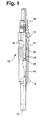
- the glow plug 10 consists of an elongated, cylindrical housing 11 with a central bore 12, the has a conical extension 13 towards the upper end. Something below this extension is at the bore 12 annular paragraph 15 formed, in that the Diameter of the bore 12 somewhat above this paragraph 15 is smaller than the diameter in the following area 12 A of the bore 12.
- the Glow plug 16 In the housing 10 is the Glow plug 16 with its tip 17 in the combustion chamber Engine immerses.
- the joint connection between Glow plug and candle housing is so far with 12 A press fit constant bore diameter on the combustion chamber.
- the projection dimension of the glow plug 16 of the glow plug is defined as the distance between the radiator tip and the test diameter on the sealing cone of the candle housing.
- the glow plug 16 On the construction of the glow plug is not further received because not essential to the invention. He can go to the Hole 12 may be conveniently pressed. One in Glow tube of the glow plug arranged filament is wider not shown. The one from the candle housing 11 protruding connecting bolts 18, is used for power supply to the electric coil.
- the connecting pin 18 is by means of a radially pressed seal 20 in the upper, no further shown tubular region of the glow plug 16, fixed.
- the seal 20 seals the glow plug 16 between Glow tube and connecting pin 18 against the environment.
- the annular paragraph 15 on the housing 11 has the purpose that the Glow plug 16 together with connecting pin 18 if the pressure in the Combustion chamber not pushed up out of the housing 11 can be.
- At the top of the glow plug 16 is a seal 20 that the radiator between the glow tube and Seals connecting bolts against the environment.
- Figures 2 and 3 show the area relevant to the invention of the annular gap 21 or the annular gap zone between Candle case and glow plug. This zone is between the combustion chamber side, constant press fit diameter of the Candle case and one inside the candle case in the Outside glow plug offset. there points the area of the glow plug on the combustion chamber side below a paragraph 16 B on a smaller diameter 16 C than that of the press fit area 12 A.
- Figure 2 shows the arrangement of the Glow plug according to the invention in the candle housing for generation an annular gap depth R1.
- Figure 3 shows the arrangement of the Glow pencil according to the invention in the candle housing for generation an annular gap depth R2.
- the glow plugs according to FIGS. 2 and 3 can have the same geometry and heating characteristics have, i.e. it can be a standard glow plug Realization of different annular gap depths (here: R1> R2) and therefore also different projection dimensions be used.
- the varying annular gap depths and projection dimensions can be realized in that the Standard glow plug correspondingly deep into the press fit of the Housing 11 is pressed.
Landscapes
- Engineering & Computer Science (AREA)
- Chemical & Material Sciences (AREA)
- Combustion & Propulsion (AREA)
- Mechanical Engineering (AREA)
- General Engineering & Computer Science (AREA)
- Resistance Heating (AREA)
- Spark Plugs (AREA)
Description
Claims (7)
- Glühstiftkerze (10) zur Anordnung im Brennraum luftverdichtender Brennkraftmaschinen mit einem rohrförmigen, metallischen Kerzengehäuse (11), in dessen Längsbohrung (12) ein Glühstift (16) mit einem Teil seiner Länge abdichtend fixiert ist, wobei sich zwischen Glühstift (16) und Kerzengehäuse (11) mindestens teilweise ein Ringspalt (21) befindet, der vom brennraumseitigen Ende des Kerzengehäuses ausgeht, dadurch gekennzeichnet, daß der Ringspalt durch eine im Durchmesser verringerte Zone (16C) am Glühstift (16) gebildet ist.
- Glühstiftkerze nach Anspruch 1, dadurch gekennzeichnet, daß unterschiedliche Ringspalttiefen (R1, R2) und Vorstehmaße mit einem einzigen Standard-Glühstift gleicher Geometrie und Aufheizcharakteristik durch variierende Einpresstiefe des Glühstiftes in den Preßsitz des Kerzengehäuses realisiert werden können.
- Glühstiftkerze nach Anspruch 2, dadurch gekennzeichnet, daß zur Verwirklichung der unterschiedlichen Ringspalttiefen (R1, R2) ein einziges Standard-Kerzengehäuse verwendet werden kann, dessen Pressitz und Ringspalt in Richtung Brennraum einen konstanten Durchmesser oder eine beliebige Durchmesserabstufung konstanter Geometrie aufweist.
- Glühstiftkerze nach einem der Ansprüche 1 bis 3, dadurch gekennzeichnet, daß die Durchmesseränderung an der Ringkante (16 B) des Glühstiftes (16) eine beliebige geometrische Gestalt aufweist und der Glühstift derart in das Kerzengehäuse eingepreßt ist, daß die Durchmesserabstufung innerhalb des Kerzengehäuses erfolgt.
- Glühstiftkerze nach einem der Ansprüche 1 bis 4, dadurch gekennzeichnet, daß der Bereich der Durchmesseraufweitung des Glühstiftes (16) innerhalb des Kerzengehäuses einen geringeren Umformgrad des Glührohrs erfordert.
- Glühstiftkerze nach einem der Ansprüche 1 bis 5, dadurch gekennzeichnet, daß die Durchmesserabstufung am Glühstift insbesondere durch Hämmern, Walzen, Ziehen oder Kaltfließpressen erfolgt.
- Glühstiftkerze nach einem der Ansprüche 1 bis 6, dadurch gekennzeichnet, daß im Inneren des Kerzengehäuses eine Ringkante (15) gebildet ist, die geringfügig kleiner ist, als der Außendurchmesser des Glühstiftstiftes (16) in diesem Bereich.
Applications Claiming Priority (3)
| Application Number | Priority Date | Filing Date | Title |
|---|---|---|---|
| DE19752920A DE19752920A1 (de) | 1997-11-28 | 1997-11-28 | Glühstiftkerze |
| DE19752920 | 1997-11-28 | ||
| PCT/DE1998/003503 WO1999028679A1 (de) | 1997-11-28 | 1998-11-30 | Glühstiftkerze |
Publications (2)
| Publication Number | Publication Date |
|---|---|
| EP1034399A1 EP1034399A1 (de) | 2000-09-13 |
| EP1034399B1 true EP1034399B1 (de) | 2002-04-10 |
Family
ID=7850183
Family Applications (1)
| Application Number | Title | Priority Date | Filing Date |
|---|---|---|---|
| EP98962285A Expired - Lifetime EP1034399B1 (de) | 1997-11-28 | 1998-11-30 | Glühstiftkerze |
Country Status (5)
| Country | Link |
|---|---|
| EP (1) | EP1034399B1 (de) |
| JP (1) | JP4188559B2 (de) |
| DE (2) | DE19752920A1 (de) |
| ES (1) | ES2175833T3 (de) |
| WO (1) | WO1999028679A1 (de) |
Families Citing this family (1)
| Publication number | Priority date | Publication date | Assignee | Title |
|---|---|---|---|---|
| DE10041282B4 (de) * | 2000-08-22 | 2005-02-10 | Beru Ag | Verfahren zur Verbindung eines Heizstabes einer Glühkerze mit ihrem Glühkerzenkörper und eine entsprechende Glühkerze |
Family Cites Families (2)
| Publication number | Priority date | Publication date | Assignee | Title |
|---|---|---|---|---|
| DE8500986U1 (de) * | 1985-01-16 | 1985-04-25 | BERU Ruprecht GmbH & Co KG, 7140 Ludwigsburg | Glühkerze |
| JP2847565B2 (ja) * | 1990-04-27 | 1999-01-20 | 日本特殊陶業株式会社 | シーズ型グロープラグ及びその製造方法 |
-
1997
- 1997-11-28 DE DE19752920A patent/DE19752920A1/de not_active Withdrawn
-
1998
- 1998-11-30 WO PCT/DE1998/003503 patent/WO1999028679A1/de not_active Ceased
- 1998-11-30 DE DE59803784T patent/DE59803784D1/de not_active Expired - Lifetime
- 1998-11-30 JP JP2000523502A patent/JP4188559B2/ja not_active Expired - Fee Related
- 1998-11-30 ES ES98962285T patent/ES2175833T3/es not_active Expired - Lifetime
- 1998-11-30 EP EP98962285A patent/EP1034399B1/de not_active Expired - Lifetime
Also Published As
| Publication number | Publication date |
|---|---|
| ES2175833T3 (es) | 2002-11-16 |
| JP4188559B2 (ja) | 2008-11-26 |
| DE19752920A1 (de) | 1999-06-02 |
| EP1034399A1 (de) | 2000-09-13 |
| DE59803784D1 (de) | 2002-05-16 |
| WO1999028679A1 (de) | 1999-06-10 |
| JP2001525529A (ja) | 2001-12-11 |
Similar Documents
| Publication | Publication Date | Title |
|---|---|---|
| EP0859436B1 (de) | Zündkerze für eine Brennkraftmaschine | |
| EP3811474B1 (de) | Vorkammer-zündkerze mit symmetrisch angeordneten masseelektroden an der gehäuseinnenseite | |
| EP3493340A1 (de) | Zündkerze mit verlängertem gehäuse und masseelektrode an der gehäuseinnenseite | |
| DE3340359A1 (de) | Verfahren zur herstellung eines keramischen heizkoerpers und keramische gluehkerze | |
| DE112017007278B4 (de) | Zündkerze | |
| DE60224741T2 (de) | Glühkerze und Struktur für deren Befestigung am Zylinderkopf | |
| DE2746595A1 (de) | Gluehstiftkerze fuer brennkraftmaschinen | |
| EP4331067B1 (de) | Vorkammerzündkerze mit exakt einstellbarem elektrodenabstand sowie verfahren hierzu | |
| DE60223225T2 (de) | Zündkerze und Herstellungsverfahren der Zündkerze | |
| DE102017109844B4 (de) | Verfahren zum Herstellen einer Zündkerzenanordnung und Zündkerzenanordnung | |
| DE102015113175A1 (de) | Zündkerze | |
| DE112017001680T5 (de) | Zündkerze für eine Verbrennungskraftmaschine und Verfahren zum Herstellen derselben | |
| DE10340043B4 (de) | Zündkerze | |
| DE2935424C2 (de) | ||
| DE60224915T2 (de) | Zündkerze und Herstellungsverfahren der Zündkerze | |
| DE102004016555A1 (de) | Zündkerze | |
| DE102010011739A1 (de) | Zündkerze und Verfahren zur Herstellung einer Zündkerze | |
| DE10041282B4 (de) | Verfahren zur Verbindung eines Heizstabes einer Glühkerze mit ihrem Glühkerzenkörper und eine entsprechende Glühkerze | |
| DE19752920A1 (de) | Glühstiftkerze | |
| DE602004012002T2 (de) | Herstellungsverfahren eines metallischen Gehäuses für eine Zündkerze, Herstellungsverfahren einer Zündkerze mit einem metallischen Gehäuse und Zündkerze hiermit hergestellt | |
| DE10248045B4 (de) | Glühkerze | |
| EP1881573A2 (de) | Zündeinrichtung, insbesondere Zündkerze für eine Verbrennungsmaschine und Verfahren zur Positionierung von wenigstens einer Masseelektrode in der Zündeinrichtung. | |
| DE10156949B4 (de) | Zündkerze | |
| EP1456922B1 (de) | Abdichtvorrichtung und verfahren zur abdichtung | |
| DE102013104992A1 (de) | Glühkerze |
Legal Events
| Date | Code | Title | Description |
|---|---|---|---|
| PUAI | Public reference made under article 153(3) epc to a published international application that has entered the european phase |
Free format text: ORIGINAL CODE: 0009012 |
|
| 17P | Request for examination filed |
Effective date: 20000628 |
|
| AK | Designated contracting states |
Kind code of ref document: A1 Designated state(s): CH DE ES FR GB IT LI SE |
|
| 17Q | First examination report despatched |
Effective date: 20001206 |
|
| GRAG | Despatch of communication of intention to grant |
Free format text: ORIGINAL CODE: EPIDOS AGRA |
|
| GRAG | Despatch of communication of intention to grant |
Free format text: ORIGINAL CODE: EPIDOS AGRA |
|
| GRAH | Despatch of communication of intention to grant a patent |
Free format text: ORIGINAL CODE: EPIDOS IGRA |
|
| REG | Reference to a national code |
Ref country code: GB Ref legal event code: IF02 |
|
| GRAH | Despatch of communication of intention to grant a patent |
Free format text: ORIGINAL CODE: EPIDOS IGRA |
|
| GRAA | (expected) grant |
Free format text: ORIGINAL CODE: 0009210 |
|
| AK | Designated contracting states |
Kind code of ref document: B1 Designated state(s): CH DE ES FR GB IT LI SE |
|
| REG | Reference to a national code |
Ref country code: CH Ref legal event code: EP |
|
| REF | Corresponds to: |
Ref document number: 59803784 Country of ref document: DE Date of ref document: 20020516 |
|
| REG | Reference to a national code |
Ref country code: CH Ref legal event code: NV Representative=s name: SCINTILLA AG, DIREKTION |
|
| GBT | Gb: translation of ep patent filed (gb section 77(6)(a)/1977) |
Effective date: 20020705 |
|
| ET | Fr: translation filed | ||
| REG | Reference to a national code |
Ref country code: ES Ref legal event code: FG2A Ref document number: 2175833 Country of ref document: ES Kind code of ref document: T3 |
|
| PLBE | No opposition filed within time limit |
Free format text: ORIGINAL CODE: 0009261 |
|
| STAA | Information on the status of an ep patent application or granted ep patent |
Free format text: STATUS: NO OPPOSITION FILED WITHIN TIME LIMIT |
|
| 26N | No opposition filed |
Effective date: 20030113 |
|
| PGFP | Annual fee paid to national office [announced via postgrant information from national office to epo] |
Ref country code: SE Payment date: 20051122 Year of fee payment: 8 |
|
| PGFP | Annual fee paid to national office [announced via postgrant information from national office to epo] |
Ref country code: CH Payment date: 20051123 Year of fee payment: 8 |
|
| PG25 | Lapsed in a contracting state [announced via postgrant information from national office to epo] |
Ref country code: LI Free format text: LAPSE BECAUSE OF NON-PAYMENT OF DUE FEES Effective date: 20061130 Ref country code: CH Free format text: LAPSE BECAUSE OF NON-PAYMENT OF DUE FEES Effective date: 20061130 |
|
| PG25 | Lapsed in a contracting state [announced via postgrant information from national office to epo] |
Ref country code: SE Free format text: LAPSE BECAUSE OF NON-PAYMENT OF DUE FEES Effective date: 20061201 |
|
| REG | Reference to a national code |
Ref country code: CH Ref legal event code: PL |
|
| EUG | Se: european patent has lapsed | ||
| PGFP | Annual fee paid to national office [announced via postgrant information from national office to epo] |
Ref country code: ES Payment date: 20091123 Year of fee payment: 12 |
|
| PGFP | Annual fee paid to national office [announced via postgrant information from national office to epo] |
Ref country code: GB Payment date: 20091123 Year of fee payment: 12 |
|
| PGFP | Annual fee paid to national office [announced via postgrant information from national office to epo] |
Ref country code: IT Payment date: 20101123 Year of fee payment: 13 |
|
| GBPC | Gb: european patent ceased through non-payment of renewal fee |
Effective date: 20101130 |
|
| PG25 | Lapsed in a contracting state [announced via postgrant information from national office to epo] |
Ref country code: GB Free format text: LAPSE BECAUSE OF NON-PAYMENT OF DUE FEES Effective date: 20101130 |
|
| REG | Reference to a national code |
Ref country code: ES Ref legal event code: FD2A Effective date: 20120110 |
|
| PG25 | Lapsed in a contracting state [announced via postgrant information from national office to epo] |
Ref country code: ES Free format text: LAPSE BECAUSE OF NON-PAYMENT OF DUE FEES Effective date: 20101201 |
|
| PG25 | Lapsed in a contracting state [announced via postgrant information from national office to epo] |
Ref country code: IT Free format text: LAPSE BECAUSE OF NON-PAYMENT OF DUE FEES Effective date: 20121130 |
|
| REG | Reference to a national code |
Ref country code: FR Ref legal event code: PLFP Year of fee payment: 18 |
|
| REG | Reference to a national code |
Ref country code: FR Ref legal event code: PLFP Year of fee payment: 19 |
|
| PGFP | Annual fee paid to national office [announced via postgrant information from national office to epo] |
Ref country code: FR Payment date: 20161124 Year of fee payment: 19 |
|
| PGFP | Annual fee paid to national office [announced via postgrant information from national office to epo] |
Ref country code: DE Payment date: 20170126 Year of fee payment: 19 |
|
| REG | Reference to a national code |
Ref country code: DE Ref legal event code: R119 Ref document number: 59803784 Country of ref document: DE |
|
| REG | Reference to a national code |
Ref country code: FR Ref legal event code: ST Effective date: 20180731 |
|
| PG25 | Lapsed in a contracting state [announced via postgrant information from national office to epo] |
Ref country code: DE Free format text: LAPSE BECAUSE OF NON-PAYMENT OF DUE FEES Effective date: 20180602 Ref country code: FR Free format text: LAPSE BECAUSE OF NON-PAYMENT OF DUE FEES Effective date: 20171130 |