EP1034460B1 - Preiswertes elektrisches gerät mit parametrierbarer funktion - Google Patents
Preiswertes elektrisches gerät mit parametrierbarer funktion Download PDFInfo
- Publication number
- EP1034460B1 EP1034460B1 EP98952827A EP98952827A EP1034460B1 EP 1034460 B1 EP1034460 B1 EP 1034460B1 EP 98952827 A EP98952827 A EP 98952827A EP 98952827 A EP98952827 A EP 98952827A EP 1034460 B1 EP1034460 B1 EP 1034460B1
- Authority
- EP
- European Patent Office
- Prior art keywords
- potentiometer
- electrical apparatus
- indexation
- actuation member
- analogue
- Prior art date
- Legal status (The legal status is an assumption and is not a legal conclusion. Google has not performed a legal analysis and makes no representation as to the accuracy of the status listed.)
- Expired - Lifetime
Links
Images



Classifications
-
- G—PHYSICS
- G05—CONTROLLING; REGULATING
- G05B—CONTROL OR REGULATING SYSTEMS IN GENERAL; FUNCTIONAL ELEMENTS OF SUCH SYSTEMS; MONITORING OR TESTING ARRANGEMENTS FOR SUCH SYSTEMS OR ELEMENTS
- G05B19/00—Program-control systems
- G05B19/02—Program-control systems electric
- G05B19/04—Program control other than numerical control, i.e. in sequence controllers or logic controllers
- G05B19/042—Program control other than numerical control, i.e. in sequence controllers or logic controllers using digital processors
- G05B19/0426—Programming the control sequence
-
- H—ELECTRICITY
- H01—ELECTRIC ELEMENTS
- H01H—ELECTRIC SWITCHES; RELAYS; SELECTORS; EMERGENCY PROTECTIVE DEVICES
- H01H19/00—Switches operated by an operating part which is rotatable about a longitudinal axis thereof and which is acted upon directly by a solid body external to the switch, e.g. by a hand
- H01H19/02—Details
- H01H19/10—Movable parts; Contacts mounted thereon
- H01H19/11—Movable parts; Contacts mounted thereon with indexing means
- H01H19/115—Movable parts; Contacts mounted thereon with indexing means using molded elastic parts only
-
- H—ELECTRICITY
- H01—ELECTRIC ELEMENTS
- H01H—ELECTRIC SWITCHES; RELAYS; SELECTORS; EMERGENCY PROTECTIVE DEVICES
- H01H19/00—Switches operated by an operating part which is rotatable about a longitudinal axis thereof and which is acted upon directly by a solid body external to the switch, e.g. by a hand
- H01H19/02—Details
- H01H19/10—Movable parts; Contacts mounted thereon
- H01H19/14—Operating parts, e.g. turn knob
-
- H—ELECTRICITY
- H01—ELECTRIC ELEMENTS
- H01H—ELECTRIC SWITCHES; RELAYS; SELECTORS; EMERGENCY PROTECTIVE DEVICES
- H01H19/00—Switches operated by an operating part which is rotatable about a longitudinal axis thereof and which is acted upon directly by a solid body external to the switch, e.g. by a hand
- H01H2019/008—Switches operated by an operating part which is rotatable about a longitudinal axis thereof and which is acted upon directly by a solid body external to the switch, e.g. by a hand with snap mounting of rotatable part on fixed part, e.g. rotor on stator, operating knob on switch panel
Definitions
- the present invention relates to an electrical appliance with configurable function at reduced cost.
- Many electrical devices have a function configurable, which means that the user of the device can assign to a sets a value chosen from among several possible values and that the device takes this value into account in its operation.
- the device usually has one or more actuators that the user can move so as to make him take a discreet position chosen from among several.
- the actuating member may be a button rotary or linear movement control, manually operable, either directly or, for very small buttons, by through a small screwdriver; the command button is accessible at the user from outside the device shell and the different discreet positions it can take are marked on the envelope the device.
- European application EP-A-0 503 265 thus describes an electrical appliance corresponding to the preamble of claim 1.
- the configurable functions can be the duration of the delay or an operating mode. Range timer values can, for example, be between 0.06 second and 30 hours.
- the operating mode relates to the operation of the or relays that the timer contains. Several operating modes exist and among the most used we find the delay in powering up or its complementary. In the first mode, the timer starts when the on the timer and the relay changes state at the end of the time delay and in the second mode, the relay changes state on power up and maintains this state for the duration of the time delay before return to its original state at the end of the time delay.
- Assigning a value to a parameter is done either through a multi-position switch, for example to set a mode or a range of values of a parameter (range of durations for a timer), either via a fine adjustment potentiometer to define a precise value of a parameter (duration setting in the chosen range).
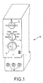
- the holes 18 at the base of the front face of the timer allow access to electrical wire clamping screws through which the timer can be connected to an electrical installation in which it performs its function.
- Switches that select ranges of parameters or operating modes can be expensive, especially if they have to have a large number of positions. They are generally arranged to supply directly in binary form a digital signal for controlling the electronic circuits which serve to establish the operation of the timer.
- a switch having a number of positions N strictly less than 2 p supplies a digital signal of p bits. The larger N, the larger p must be and the more expensive the switch will be.
- the width of the timer shown on the figure 1 could be less than 2 centimeters, and the control buttons 12, 14, and 16, as well as the switches and potentiometer which are behind the buttons do not exceed one centimeter in diameter.
- the invention aims to reduce these drawbacks altogether. by doing in so that the user has a virtually unchanged perception of the device operation.
- the present invention provides an apparatus electrical as defined in claim 1.
- the selection switch of parameter, range of parameters, or operating mode is physically replaced by an indexing potentiometer.
- This potentiometer supplied by a voltage, delivers an analog signal, and it is in the electronics of the device that this signal is converted into a numerical value (that which in the prior art was delivered by a switch) representing the index on which the organ is positioned actuation of the potentiometer.
- a numerical value that which in the prior art was delivered by a switch
- the conversion analog-digital can be part of the microcontroller which manages the entire operation of the device, so that a single input from microcontroller is then necessary to ensure the connection with the potentiometer whatever the number N of indexed positions that can take the actuator of the potentiometer.
- the potentiometer even provided with notch indexing means, is less expensive than a switch since the number of positions indexed exceeds three to four.
- control buttons remain the same and the position marking may remain unchanged; the sensation of turning a switch remains thanks to the notches of the indexing means.
- the conversion means analog-to-digital and interpretation can involve a simple analog-to-digital converter which receives analog voltage and which directly delivers the digital signal representative of the position of the actuator.
- the means of conversion analog-to-digital and interpretation can involve not only an analog-to-digital converter which receives the analog voltage and which delivers an intermediate digital signal directly representing the position of a potentiometer cursor, but also a decoding device which receives this intermediate digital signal and which transposes it into a signal digital representative of an actuator position among N posit indexes.
- the digital signal intermediate can have m bits, with m greater than the number p of bits defining a position among N.
- the track resistive is in the form of separate discontinuous resistive pads by conductive pads.
- the device has several potentiometers, it is preferable to provide a multiplexer inserted between the potentiometers and the means of analog-to-digital conversion and interpretation, which does not not multiply the number of analog-digital converters.
- the indexing means can include a first means of indexing secured to the organ actuation and a second indexing means carried by an envelope of the device.
- cooperation between indexing means is of elastic type, that is to say that a certain force recall forces the actuator to stabilize on one of the indexed positions, without remaining between two positions.
- One of the two indexing means may include at least one lug and the second means of indexing several notches, the lug coming stay in one of the notches. Or conversely, there are several lugs and one notch, the notch coming to be applied on one of the lugs.
- the exterior appearance and functionality of the timer may be exactly those that have already been described about the FIG. 1, that is to say, in this example, three possible operating modes, six duration ranges, and continuous duration adjustment in one range selected. But instead of the control buttons 12 and 14 being switch actuating organs, they become organs notch potentiometer control. The control button 16 remains the actuating member of a continuous adjustment potentiometer.
- Figure 2 shows a side section of the device, with at minus a potentiometer and its indexing control member.
- the apparatus 10 comprises an envelope 1 with a front wall 2, a potentiometer 3 placed inside the envelope, and a member actuation 4 of potentiometer 3, accessible from outside envelope 1 so that an operator can handle it.
- the organ actuation 4 is located on the front 2 but other positions would be possible. It can protrude from the front face, accessible directly by hand, or slightly behind the front face, then accessible by a screwdriver.
- the actuating member 4 comprises a first part 40 in form of cylindrical button operable from the outside of the casing 1 and this first part 40 is extended by a second part 41 in the form of rod which projects inside the envelope 1 towards the potentiometer 3.
- the rod 41 ends with an end 43 which is intended to activate the cursor 31 of potentiometer 3.
- the end 43 of the rod 41 can be cruciform, flat or flanked and enter an orifice 32 of geometry slider 31 of the potentiometer, so that the rotation of the button 40 causes the cursor to rotate.
- the detail of the potentiometer is not not shown since it can be any type of potentiometer, including a very low quality potentiometer therefore very low cost
- a simple track potentiometer will be used continuous annular resistive, on which a moving cursor rubs rotation.
- the casing 1 of the device has an opening 21, visible on Figure 2, to let the rod 41 pass. Indexing means can be spared in this opening as we will see.
- the actuator 4 which passes through the opening 21 is preferably fitted with latching means 42 in the envelope 1.
- latching means 42 for example comprise one or more tabs 42a elastic bands each terminating in a projecting element 42, by example in the form of a fin, to ensure immobilization in translation of the actuating member 4 when it has been inserted into the opening 21.
- the latching means 42a, 42b are attached to the button 40 but we could have considered. let them be united of the rod 41.
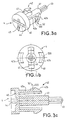
- FIGS. 3a, 3b, and 3c there is shown in more detail, respectively in perspective, in rear view, and in longitudinal section, the constitution of the actuating member 4 with the elements already described: cylindrical button 40, rod 41, latching means 42, end 43 cursor operation.
- cylindrical button 40 cylindrical button 40
- rod 41 rod 41
- latching means 42 end 43 cursor operation.
- fixed legs 47 similarly diameter than the inside diameter of the opening 21, to ensure the holding, guiding and rotating the button in the opening 21.
- the button 40 can also have slots 44 to be able to be moved precisely using a screwdriver. In some electrical appliances, button 40 will be relatively small, for example less than a centimeter in diameter and its actuation by grasping it with the fingers is not easy.
- the button 40 can also bear a mark 45, while envelope 1 bears as many marks as discrete positions of the actuator 4 and therefore only desired values of the parameter selected by the button (here: operating modes or ranges of duration).
- the mark 45 located opposite a mark of the envelope allows easily view the value selected for the parameter.
- the discrete positions that the actuator can take 4 make it possible to obtain a succession of discrete resistance values of the potentiometer. These positions are obtained by indexing means at notch with which the actuator 4 cooperate. These means indexing 52, 53 notched by decomposing in a first way indexing 52 carried by the actuating member 4 (FIGS. 3a, 3b, and 3c) and in a second indexing means 53 (FIGS. 4 and 5) fixed relative to the appliance 10.
- the first indexing means 52 integral with the organ actuation 4, is shown in Figures 3a, 3b, and 3c in the form at least one lug 520 of trapezoidal shape.
- This lug is preferably carried by one of the elastic snap tabs 42, but it is also possible to place it elsewhere.
- the second indexing means 53 fixed relative to the device 10, is located on the casing 1 and more precisely on the rear face of the front wall 2 of the device 10. It is formed of a succession of notches or notches 51 1 to 51 n , which have substantially the same trapezoidal shape as the lug 520.
- the lug 520 is intended to be housed in one of the notches 51 1 to 51 n when the actuating member 4 takes one of the desired discrete positions, and to pass from notches to notches when the actuating member 4 is actuated.
- the notches are located at the edge of the opening 21 of the envelope 1 as seen in Figures 4 (sectional view from above) and 5 (seen from the rear, that is to say from the inside of the device, from the front wall 2).
- the notches 51 1 to 51 n are arranged on the inner face of the envelope 1 and are not visible from the outside of the envelope 1. They can be molded in the envelope 1 if the envelope material 1 lends itself to it. It is of course conceivable that the notches are hollowed out on the outer face of the envelope 1. The choice depends on the position of the first indexing means 52.
- the number of notches is at least equal to the number of discrete positions 51 1 to 51 n desired for the actuating member 4, therefore to the number of values desired for the adjustment parameter of the device.
- the elasticity of the latching tabs designed to allow force insertion and maintenance of the actuating member in the opening 21, in fact also serves to recall the lug 520 inwards notches, that is to say towards the periphery of the opening 21.
- the depth notches is lower than the elastic deflection of the legs so that the lug can come out of the notches when the control button.
- the trapezoidal shape of the notches and the lug facilitates the exit of the lug out of a notch as well as its penetration in another notch.
- the support surface available between two notches is weak enough to prevent the lug from stabilizing out of a notch.
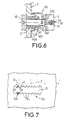
- first indexing means 52 being formed by a lug and that the second indexing means 53 of several notches, it is possible consider the opposite as illustrated in Figure 6.
- the second indexing means 53 now includes a lug 532, integral with the envelope 1 and which projects inside the envelope to the actuator.
- the first indexing means 52 comprises a succession of notches 522 carried by the rod 41 of the member actuation 4.
- the lug 532 has sufficient elasticity to allow its elastic retention in a notch, and its exit out of this notch.
- the actuating member 4 is mobile in rotation but its displacement could be a translation as shown in Figure 7.
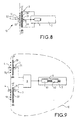
- Figure 8 shows the principle of electrical operation of the device.
- the potentiometer 3 is shown diagrammatically by a resistor 33. Its cursor 31 moves and takes the different discrete positions 51 1 under the control of its actuating member 4.
- the potentiometer is for example simply supplied by a voltage V so that a fraction of this voltage, variable discreetly, appears on its cursor.
- the potentiometer could also be mounted in a resistance bridge.
- the analog voltage Ve present on the cursor is applied to the input of electronic circuits which allow the device to execute the configurable functions for which it is intended.
- These circuits include essentially a treatment device 7 which is constituted in practice by a programmed microcontroller.
- the electronic circuits must include means of conversion analog-digital and interpretation 6, preferably integrated into the microcontroller.
- These analog-to-digital conversion means and 6 establish a digital signal of p bits, representing one of the N possible discrete positions of the indexing potentiometer, and therefore representing one of the desired values for the parameter set by this potentiometer.
- This p bit digital signal replaces the p bit signal which would have been provided in the prior art by a p-switch bits. It is directly used by the processing device 7 to make operate the device with the selected parameter value.
- the means of analog-digital conversion and interpretation include a simple converter p-bit analog-to-digital. But that assumes that the potentiometer be very precise, and very linear, so that there is a correspondence one-to-one, for each discrete cursor position, between the position cursor geometry, and the resulting p-bit signal. If one wants to use a low cost potentiometer, dispersion can be important, powered by a voltage which is not necessarily very precise, subject possibly climatic, thermal and mechanical constraints important, one-to-one correspondence will be difficult to obtain by a simple p-bit analog-to-digital converter.
- the whole converter and decoding means "constituting the means of conversion and interpretation 6 mentioned above.
- the decoding means then correspond to the different possible analog voltage values, digitally coded on p + m bits, a unique numeric value coded on p bits which represents a discrete position at which this analog voltage value is assumed match.
- coded single value on p bits corresponds precisely to the p most significant of the numerical value coded on p + m bits
- the decoding table can be arbitrary. In particular, this correspondence will generally not exist if the potentiometer is not sufficiently linear.
- the decoding means can be integrated, as can the analog-to-digital converter, in a constituent microcontroller the main part of the circuits 7.
- These decoding means can be constituted by an electrically programmable read-only memory. Faults potentiometers, or adapting the device to another potentiometer, or changes in supply voltage, can be taken into account by having a read-only memory in several different zones, or even by changing the contents of the ROM.
- the device has several potentiometers 3, you can use the same analog-digital converter for all the potentiometers, provided that a multiplexer is inserted between the potentiometers and this converter.
- This multiplexer 8 can be part of the microcontroller, to which case the microcontroller must have as many inputs as there are potentiometers. It can also be external to the microcontroller and placed in upstream of it, in which case, only one analog link is necessary between the output of the multiplexer and the microcontroller, the different potentiometers being connected to the different inputs of the multiplexer 8 as this is shown in Figure 9.
- the analog-to-digital converter is designated by a reference 61 in Figure 9, and it is followed by a means of decoding 62.
- this adjustable potentiometer continuous can be connected through the multiplexer to the same microcontroller (and in practice to the same analog-digital converter). The resulting signal is used by the device to define the end time adjustment.
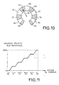
- FIG. 10 schematically represents an embodiment particular of the invention, in which the resistive track of the potentiometer, on which moves the potentiometer cursor (represented by an arrow symbolic 70), is in the form of discontinuous resistive pads R0 to R4, separated by conductive pads P0 to P5 (hatched).
- Each conductive pad is located at a position respective discrete cursor defined by notch indexing means (not shown in Figure 10).
- This particular provision is to reduce the consequences of uncertainty on the exact position of the cursor relative to the resistive track when the cursor is on an indexed position, counts given the manufacturing dispersion from one device to another.
- the resistive track is a continuous track over all the extent of the cursor movement, but it is covered locally, at the location of ranges P0 to P5, by a conductive layer which short-circuits locally the resistive track and therefore gives it a configuration discontinuous.
- Silver paste can be used for the diaper conductive.
- Figure 12 shows an exploded view of a practical example of embodiment in which the notch indexing means 71, 72 are part of the potentiometer 3 itself and in which the resistive track R is rendered discontinuous by the use of conductive pads P locally covering, at the location of the indexed positions of the cursor 70 the resistive track.
- the potentiometer shown has three parts 80, 81, 82.
- the part 80, on the right in the figure is a case which contains at the level of its melts the resistive track 73 formed of discontinuous resistive pads R separated by conductive pads P.
- the two ends of the resistive track 73 are connected each to a conductive tab 83 which comes out of the housing.
- the ends of runway 73 are located at beaches conductive P.
- the middle part 81 movable in rotation is housed in the housing.
- It comprises a conductive crown 86 provided with a part in relief 70 which forms the cursor and which comes into contact with the resistive track 73 when the middle part 81 is mounted in the housing 80.
- the part in relief 70 is V-shaped in the example described.
- This conductive crown 86 is mounted around an axis insulator 85 which is used to actuate the cursor 70 in rotation.
- mounting the insulating pin 85 comes from one side in support at the bottom of the housing.
- axis 85 is accessible from the outside of the housing to allow actuation of the crown and therefore of the cursor 70.
- the axis 85 is hollow and can be rotated with a screwdriver to move cursor 70.
- the last part 82 is a cover which is secured to the case 80 to close it.
- the cover 82 has an opening 87 to allow passage the insulating axis 85.
- the notch indexing means 71, 72 are constituted simply by bosses cooperating with each other.
- the first indexing means 71 is formed at least of a boss, carried by the crown 86, in relief towards the cover 82 in the example described.
- the second indexing means 72 is made up of several bosses, carried by the cover 82, recessed towards the crown 86.
- a boss 71 carried by the crown 86 in relief towards the cover 82 comes lodge in one of the bosses 72 carried by the cover.
- the number of bosses 72 corresponds to the number of discrete positions desired by the actuator. We can of course use a boss 71 recessed towards the cover 82 and bosses 72 in relief towards the crown 86.
- the crown 86 carrying the boss 71 has a certain elasticity given by a slot 88 located at the level of the cursor 70.
- the cover 82 is conductive and has a tab 89 conductive which collects the voltage present at the cursor 70. To correctly position the cover 82 relative to the housing 80 and prevent it from rotating, it is possible to provide for the cover 82 to include minus a tab 91 which is housed in a notch 90 of the housing 80.
Landscapes
- General Physics & Mathematics (AREA)
- Engineering & Computer Science (AREA)
- Automation & Control Theory (AREA)
- Physics & Mathematics (AREA)
- Adjustable Resistors (AREA)
- Control Of Electric Motors In General (AREA)
- Measuring Instrument Details And Bridges, And Automatic Balancing Devices (AREA)
- Transmission And Conversion Of Sensor Element Output (AREA)
- Arrangements For Transmission Of Measured Signals (AREA)
- Feedback Control In General (AREA)
- Measuring Pulse, Heart Rate, Blood Pressure Or Blood Flow (AREA)
- Diaphragms For Electromechanical Transducers (AREA)
- Percussion Or Vibration Massage (AREA)
- Control Of Position Or Direction (AREA)
- Executing Machine-Instructions (AREA)
- Oscillators With Electromechanical Resonators (AREA)
Claims (20)
- Elektrisches Gerät, das wenigstens eine parametrisierbare Funktion besitzt, mit wenigstens einem Potentiometer (3), das ein Betätigungselement (4) besitzt, das Positionen (511 bis 51n) einnehmen kann, wovon jede (51i) einem gewünschten Wert eines Parameters entspricht, und mit Analog/Digital-Umsetzungs- und Interpretationsmitteln (6), die eine vom Potentiometer (3) in Abhängigkeit von der vom Betätigungselement (4) eingenommenen Position (51i) gelieferte analoge Spannung (Ve) empfangen und ein digitales Signal ausgeben, das die Position (51i) des Betätigungselements (4) und daher den gewünschten Wert für den Parameter darstellt, wobei dieses digitale Signal als Steuersignal für die Parametrisierung des Geräts dient, dadurch gekennzeichnet, daß die Positionen, die das Betätigungselement einnehmen kann, diskrete Positionen sind, wobei das Betätigungselement (4) mit Rasten-Indexierungsmitteln (52, 53) zusammenwirkt, die diese diskreten Positionen gegenständlich darstellen.
- Elektrisches Gerät nach Anspruch 1, dadurch gekennzeichnet, daß die Analog/Digital-Umsetzungs- und Interpretationsmittel (6) einen Analog/Digital-Umsetzer enthalten, der die analoge Spannung (Ve) empfängt und das die Position (51i) des Betätigungselements (4) darstellende digitale Signal ausgibt.
- Elektrisches Gerät nach Anspruch 1, dadurch gekennzeichnet, daß die Analog/Digital-Umsetzungs- und Interpretationsmittel (6) einen Analog/Digital-Umsetzer (61) umfassen, der die analoge Spannung (Ve) empfängt und ein digitales Zwischensignal an eine Decodierungsvorrichtung (62) ausgibt, die ihrerseits das die Position (51i) des Betätigungselements (4) darstellende digitale Signal ausgibt.
- Elektrisches Gerät nach Anspruch 3, dadurch gekennzeichnet, daß der Umsetzer (61) ein mit p + m Bits codiertes digitales Signal ausgibt und daß die Decodierungsvorrichtung (62) anhand des mit p + m Bits codierten Signals ein mit p Bits codiertes Signal ausgibt.
- Elektrisches Gerät nach einem der Ansprüche 2 bis 4, das eine Verarbeitungsvorrichtung (7) enthält, die das die Position (51i) des Betätigungselements (4) darstellende digitale Signal auswertet, um für das Gerät eine Funktion mit einem ausgewählten Parameter auszuführen, dadurch gekennzeichnet, daß der Analog/Digital-Umsetzer (6, 61) in die Verarbeitungsvorrichtung (7) integriert ist.
- Elektrisches Gerät nach Anspruch 5, dadurch gekennzeichnet, daß die Decodierungsvorrichtung (62) in die Verarbeitungsvorrichtung (7) integriert ist.
- Elektrisches Gerät nach einem der Ansprüche 1 bis 6, das mehrere Potentiometer (3) umfaßt, dadurch gekennzeichnet, daß zwischen die Potentiometer (3) und die Analog/Digital-Umsetzungs- und Interpretationsmittel (6) ein Multiplexer (8) geschaltet ist.
- Elektrisches Gerät nach einem der Ansprüche 1 bis 7, dadurch gekennzeichnet, daß die Indexierungsmittel (52, 53) ein mit dem Betätigungselement (4) fest verbundenes erstes Indexierungsmittel (52) und ein von einem Gehäuse (1) des Geräts (10) getragenes zweites Indexierungsmittel (53) umfassen.
- Elektrisches Gerät nach Anspruch 8, dadurch gekennzeichnet, daß das erste Indexierungsmittel (52) und/oder das zweite Indexierungsmittel (53) elastisch sind.
- Elektrisches Gerät nach einem der Ansprüche 8 oder 9, dadurch gekennzeichnet, daß eines der Indexierungsmittel (52) wenigstens einen Vorsprung (520) und das andere (53) mehrere Rasten (511 bis 51n) umfaßt, wobei der Vorsprung (520) von einer der Rasten (51i) aufgenommen wird.
- Elektrisches Gerät nach einem der Ansprüche 8 oder 9, dadurch gekennzeichnet, daß eines der Indexierungsmittel mehrere Vorsprünge umfaßt und das andere wenigstens eine Raste umfaßt, wobei die Raste auf einen der Vorsprünge angewendet wird.
- Elektrisches Gerät nach einem der Ansprüche 8 bis 11, dadurch gekennzeichnet, daß das Betätigungselement (4) das Gehäuse (1) des Geräts durch eine Öffnung (21) durchquert und elastische Einrastmittel (42) in dieser Öffnung (21) aufweist und daß das erste Indexierungsmittel (52) von den elastischen Einrastmitteln (42) getragen wird.
- Elektrisches Gerät nach Anspruch 12, dadurch gekennzeichnet, daß sich das zweite Indexierungsmittel (53) am Rand der Öffnung (21) befindet.
- Elektrisches Gerät nach einem der Ansprüche 1 bis 7, dadurch gekennzeichnet, daß die Indexierungsmittel (71, 72) einen Teil des Potentiometers bilden.
- Elektrisches Gerät nach Anspruch 14, dadurch gekennzeichnet, daß die Indexierungsmittel (71, 72) Höcker sind, die zusammenwirken.
- Gerät nach einem der Ansprüche 1 bis 15, dadurch gekennzeichnet, daß das Potentiometer eine Bahn mit ohmschem Widerstand aufweist, die die Form diskontinuierlicher ohmscher Bereiche (R0 bis R4) besitzt, die durch leitende Bereiche (P0 bis P5) getrennt sind.
- Gerät nach Anspruch 16, dadurch gekennzeichnet, daß die diskontinuierlichen ohmschen Bereiche (R0 bis R4) aus einer kontinuierlichen ohmschen Bahn gebildet sind, die lokal durch eine leitende Schicht bedeckt ist.
- Gerät nach einem der Ansprüche 1 bis 17, dadurch gekennzeichnet, daß der Parameter eine Betriebsart des Geräts von mehreren möglichen Betriebsarten ist.
- Gerät nach einem der Ansprüche 1 bis 17, dadurch gekennzeichnet, daß der Parameter ein Wertebereich von mehreren möglichen Bereichen eines weiteren Parameters ist.
- Gerät nach einem der Ansprüche 18 und 19, dadurch gekennzeichnet, daß es ein Uhrwerk bildet, das wenigstens ein Indexierungspotentiometer für die Definition einer Betriebsart und/oder ein Indexierungspotentiometer für die Definition eines Bereichs von Zeitdauern besitzt.
Applications Claiming Priority (3)
| Application Number | Priority Date | Filing Date | Title |
|---|---|---|---|
| FR9715011 | 1997-11-28 | ||
| FR9715011A FR2771825B1 (fr) | 1997-11-28 | 1997-11-28 | Appareil electrique a fonction parametrable a cout reduit |
| PCT/FR1998/002331 WO1999028796A1 (fr) | 1997-11-28 | 1998-10-30 | Appareil electrique a fonction parametrable a cout reduit |
Publications (2)
| Publication Number | Publication Date |
|---|---|
| EP1034460A1 EP1034460A1 (de) | 2000-09-13 |
| EP1034460B1 true EP1034460B1 (de) | 2001-09-12 |
Family
ID=9513942
Family Applications (1)
| Application Number | Title | Priority Date | Filing Date |
|---|---|---|---|
| EP98952827A Expired - Lifetime EP1034460B1 (de) | 1997-11-28 | 1998-10-30 | Preiswertes elektrisches gerät mit parametrierbarer funktion |
Country Status (8)
| Country | Link |
|---|---|
| US (1) | US6351232B1 (de) |
| EP (1) | EP1034460B1 (de) |
| AT (1) | ATE205609T1 (de) |
| AU (1) | AU1038199A (de) |
| DE (1) | DE69801681T2 (de) |
| ES (1) | ES2161549T3 (de) |
| FR (1) | FR2771825B1 (de) |
| WO (1) | WO1999028796A1 (de) |
Families Citing this family (18)
| Publication number | Priority date | Publication date | Assignee | Title |
|---|---|---|---|---|
| DE10203509B4 (de) * | 2002-01-30 | 2005-01-13 | Whirlpool Corp., Benton Harbor | Rastvorrichtung für einen mehrstufigen Drehschalter |
| CN101507060B (zh) * | 2006-06-30 | 2011-08-10 | 莫列斯公司 | 低轮廓闭锁连接器 |
| US7550939B2 (en) * | 2006-07-14 | 2009-06-23 | William Davison | Redundant instantaneous trip detection |
| US7869170B2 (en) * | 2006-07-14 | 2011-01-11 | Susan Jean Walker Colsch | Method and system for time synchronized trip algorithms for breaker self protection |
| US7869169B2 (en) * | 2006-07-14 | 2011-01-11 | William Davison | Method and system of current transformer output magnitude compensation in a circuit breaker system |
| US7859802B2 (en) * | 2006-07-14 | 2010-12-28 | William Davison | Burden resistor temperature compensation algorithm |
| US7683586B2 (en) * | 2006-07-14 | 2010-03-23 | Davison William C | Method and system of fault powered supply voltage regulation |
| US7788055B2 (en) | 2006-07-14 | 2010-08-31 | Square D Company | Method and system of calibrating sensing components in a circuit breaker system |
| US7791849B2 (en) * | 2006-07-14 | 2010-09-07 | William Davison | Redundant trip activation |
| US7697250B2 (en) * | 2006-07-14 | 2010-04-13 | William Davison | Switch-to-trip point translation |
| US7592888B2 (en) * | 2006-07-14 | 2009-09-22 | Jason Robert Colsch | Low cost user adjustment, resistance to straying between positions, increased resistance to ESD, and consistent feel |
| US8154373B2 (en) * | 2006-07-14 | 2012-04-10 | Schneider Electric USA, Inc. | Circuit breaker-like apparatus with combination current transformer |
| FR2913143A1 (fr) * | 2007-02-27 | 2008-08-29 | Schneider Electric Ind Sas | Dispositif de commande d'un composant d'une carte electronique et systeme de declenchement le comprenant. |
| DE102007012766B4 (de) * | 2007-03-16 | 2014-05-22 | Pepperl + Fuchs Gmbh | Optischer Sensor |
| DE102009033536A1 (de) * | 2009-07-10 | 2011-01-13 | Dr. Ing. H.C. F. Porsche Aktiengesellschaft | Betätigungsvorrichtung |
| JP5895722B2 (ja) * | 2012-06-07 | 2016-03-30 | オムロン株式会社 | 回転操作部品および電子機器 |
| KR101513210B1 (ko) * | 2013-11-11 | 2015-04-17 | 엘에스산전 주식회사 | 과전류 계전기 |
| JP6987249B2 (ja) * | 2017-12-12 | 2021-12-22 | レイセオン カナダ リミテッド | 非シーケンシャル一意的ビットパターンを有する回転スイッチその他のエンコーダ及びその設計方法 |
Family Cites Families (12)
| Publication number | Priority date | Publication date | Assignee | Title |
|---|---|---|---|---|
| GB2069192A (en) * | 1980-01-24 | 1981-08-19 | Plessey Co Ltd | Programmable timed control arrangements |
| US4420669A (en) * | 1981-06-15 | 1983-12-13 | Texas Instruments Incorporated | Data input apparatus for microwave oven controllers |
| US4342271A (en) * | 1981-08-13 | 1982-08-03 | The Singer Company | Stitch length range indicating arrangement in a multiple pattern sewing machine |
| US4551618A (en) * | 1981-12-23 | 1985-11-05 | General Electric Company | Cooking appliance incorporating heater energy counter means |
| SE457388B (sv) * | 1985-06-04 | 1988-12-19 | Gambro Ab | Monitor foer styrning och/eller kontroll av tvaa eller flera funktioner samt anvaendning av en saadan foer styrning av en vaetskestroem |
| FR2602926B1 (fr) * | 1986-08-14 | 1992-12-24 | Telemecanique Electrique | Dispositif de reglage et de dialogue notamment pour variateur de vitesse |
| IT1225853B (it) * | 1988-08-31 | 1990-12-07 | Zanussi A Spa Industrie | Dispositivo di controllo per macchine lavatrici e/o asciugatrici di biancheria |
| DE59208474D1 (de) * | 1991-02-04 | 1997-06-19 | Vaillant Joh Gmbh & Co | Eingabeeinrichtung für einen programmierbaren Heizungsregler |
| FR2683835B1 (fr) * | 1991-11-15 | 1994-02-18 | Ciapem | Lave-linge ou seche-linge a programmateur comprenant deux bases de temps de types differents. |
| US5574350A (en) * | 1993-11-08 | 1996-11-12 | Grapha-Holding Ag | Motor-operated adjusting device for machines |
| DE19620575A1 (de) * | 1996-05-22 | 1997-11-27 | Kloeckner Moeller Gmbh | Schaltungsanordnung zur Einstellung der Parameter von elektronischen Geräten |
| US5874938A (en) * | 1996-08-30 | 1999-02-23 | Usar System Inc. | Pointing device with reduced component count |
-
1997
- 1997-11-28 FR FR9715011A patent/FR2771825B1/fr not_active Expired - Fee Related
-
1998
- 1998-10-30 AT AT98952827T patent/ATE205609T1/de not_active IP Right Cessation
- 1998-10-30 US US09/555,374 patent/US6351232B1/en not_active Expired - Lifetime
- 1998-10-30 EP EP98952827A patent/EP1034460B1/de not_active Expired - Lifetime
- 1998-10-30 AU AU10381/99A patent/AU1038199A/en not_active Abandoned
- 1998-10-30 DE DE69801681T patent/DE69801681T2/de not_active Expired - Lifetime
- 1998-10-30 WO PCT/FR1998/002331 patent/WO1999028796A1/fr not_active Ceased
- 1998-10-30 ES ES98952827T patent/ES2161549T3/es not_active Expired - Lifetime
Also Published As
| Publication number | Publication date |
|---|---|
| FR2771825B1 (fr) | 2001-06-08 |
| US6351232B1 (en) | 2002-02-26 |
| DE69801681D1 (de) | 2001-10-18 |
| ES2161549T3 (es) | 2001-12-01 |
| ATE205609T1 (de) | 2001-09-15 |
| WO1999028796A1 (fr) | 1999-06-10 |
| DE69801681T2 (de) | 2002-06-20 |
| EP1034460A1 (de) | 2000-09-13 |
| FR2771825A1 (fr) | 1999-06-04 |
| AU1038199A (en) | 1999-06-16 |
Similar Documents
| Publication | Publication Date | Title |
|---|---|---|
| EP1034460A1 (de) | Preiswertes elektrisches gerät mit parametrierbarer funktion | |
| EP0446088B1 (de) | Schalter mit Berührungseffekt und diesen Schalter verwendende Tastatur | |
| EP0181905B1 (de) | Vorrichtung zur darstellung taktiler informationen | |
| EP0597753A1 (de) | Kompaktes, ergonomisches Kommunikationsendgerät, ausgestattet mit Flächen zur Näherungsdetektion | |
| FR2613850A1 (fr) | Dispositif de saisie de donnees, notamment pour appareil a microprocesseur | |
| FR2796755A1 (fr) | Commutateur electrique a organe unique d'actionnement rotatif et axial | |
| FR2682218A1 (fr) | Dispositif de contacteur. | |
| WO1980001632A1 (fr) | Systeme de traitement de signaux a attenuateur electronique multivoies et a reglages memorises | |
| FR2899719A1 (fr) | Commutateur electrique a voies de commutation multiples | |
| EP0402257B1 (de) | Brotröster mit mehreren Funktionen | |
| FR2498369A1 (fr) | Colonne de montage d'une diode electroluminescente ou autre element d'eclairage dans un commutateur a bouton-poussoir eclaire | |
| FR2856191A1 (fr) | Dispositif de commande a tambour et a voies de commutation multiples, et appareil electronique equipe de tels dispositifs | |
| EP0389366B1 (de) | Schalthebelgriff, insbesondere für Kraftfahrzeuge mit zwei Drehringen | |
| EP0446770B1 (de) | Wecker | |
| EP1134630A1 (de) | Vorrichtung um Informationen mit einem tragbaren Objekt, insbesondere einer Armbanduhr, auszutauschen | |
| EP1632840B1 (de) | Pipette mit einem Funktionsrad | |
| FR2571174A1 (fr) | Mecanisme d'actionnement d'un interrupteur, notamment d'un interrupteur de commande d'un lave-glace/essuie-glace d'un vehicule automobile | |
| FR2584877A1 (fr) | Circuit de reglage des fonctions de declenchement d'un disjoncteur electronique | |
| FR2571176A1 (fr) | Interrupteur de commande temporisee d'un balai mobile notamment d'un balai d'essuie-glace d'un vehicule automobile | |
| EP0828260B1 (de) | Steuerkreislauf für die Positionierung eines beweglichen Organs, insbesondere verwendet in einer Steuerungseinrichtung zur Neigung eines Fahrzeugscheinwerfers, und Verfahren zur Herstellung | |
| WO2000012223A1 (fr) | Applicateur de colle thermofusible et batonnet de colle conçu pour alimenter un tel applicateur | |
| EP0886292B1 (de) | Schalter mit niedriger Abmessung für Steuertafel insbesondere für Vorrichtungen zur Heizung, Lüftung und/oder Klimatisierung eines Fahrzeuges | |
| EP0233421A1 (de) | Einrichtung zur Einstellung der Position wenigstens eines Teils der Elemente eines Sitzes, insbesondere des Sitzes eines Automobils | |
| FR2792486A1 (fr) | Commutateur electrique multiple a tambour unique d'actionnement | |
| EP0489383B1 (de) | Steuervorrichtung für Mikrowellenofen |
Legal Events
| Date | Code | Title | Description |
|---|---|---|---|
| PUAI | Public reference made under article 153(3) epc to a published international application that has entered the european phase |
Free format text: ORIGINAL CODE: 0009012 |
|
| 17P | Request for examination filed |
Effective date: 20000525 |
|
| AK | Designated contracting states |
Kind code of ref document: A1 Designated state(s): AT BE CH DE DK ES FR GB IT LI NL SE |
|
| GRAG | Despatch of communication of intention to grant |
Free format text: ORIGINAL CODE: EPIDOS AGRA |
|
| 17Q | First examination report despatched |
Effective date: 20001027 |
|
| GRAG | Despatch of communication of intention to grant |
Free format text: ORIGINAL CODE: EPIDOS AGRA |
|
| GRAH | Despatch of communication of intention to grant a patent |
Free format text: ORIGINAL CODE: EPIDOS IGRA |
|
| GRAH | Despatch of communication of intention to grant a patent |
Free format text: ORIGINAL CODE: EPIDOS IGRA |
|
| GRAA | (expected) grant |
Free format text: ORIGINAL CODE: 0009210 |
|
| AK | Designated contracting states |
Kind code of ref document: B1 Designated state(s): AT BE CH DE DK ES FR GB IT LI NL SE |
|
| PG25 | Lapsed in a contracting state [announced via postgrant information from national office to epo] |
Ref country code: SE Free format text: LAPSE BECAUSE OF FAILURE TO SUBMIT A TRANSLATION OF THE DESCRIPTION OR TO PAY THE FEE WITHIN THE PRESCRIBED TIME-LIMIT Effective date: 20010912 Ref country code: NL Free format text: LAPSE BECAUSE OF FAILURE TO SUBMIT A TRANSLATION OF THE DESCRIPTION OR TO PAY THE FEE WITHIN THE PRESCRIBED TIME-LIMIT Effective date: 20010912 Ref country code: GB Free format text: LAPSE BECAUSE OF FAILURE TO SUBMIT A TRANSLATION OF THE DESCRIPTION OR TO PAY THE FEE WITHIN THE PRESCRIBED TIME-LIMIT Effective date: 20010912 Ref country code: AT Free format text: LAPSE BECAUSE OF FAILURE TO SUBMIT A TRANSLATION OF THE DESCRIPTION OR TO PAY THE FEE WITHIN THE PRESCRIBED TIME-LIMIT Effective date: 20010912 |
|
| REF | Corresponds to: |
Ref document number: 205609 Country of ref document: AT Date of ref document: 20010915 Kind code of ref document: T |
|
| REG | Reference to a national code |
Ref country code: CH Ref legal event code: EP |
|
| REF | Corresponds to: |
Ref document number: 69801681 Country of ref document: DE Date of ref document: 20011018 |
|
| PG25 | Lapsed in a contracting state [announced via postgrant information from national office to epo] |
Ref country code: BE Free format text: LAPSE BECAUSE OF NON-PAYMENT OF DUE FEES Effective date: 20011031 |
|
| REG | Reference to a national code |
Ref country code: ES Ref legal event code: FG2A Ref document number: 2161549 Country of ref document: ES Kind code of ref document: T3 |
|
| PG25 | Lapsed in a contracting state [announced via postgrant information from national office to epo] |
Ref country code: DK Free format text: LAPSE BECAUSE OF FAILURE TO SUBMIT A TRANSLATION OF THE DESCRIPTION OR TO PAY THE FEE WITHIN THE PRESCRIBED TIME-LIMIT Effective date: 20011212 |
|
| NLV1 | Nl: lapsed or annulled due to failure to fulfill the requirements of art. 29p and 29m of the patents act | ||
| GBV | Gb: ep patent (uk) treated as always having been void in accordance with gb section 77(7)/1977 [no translation filed] |
Effective date: 20010912 |
|
| BERE | Be: lapsed |
Owner name: CROUZET AUTOMATISMES Effective date: 20011031 |
|
| PLBE | No opposition filed within time limit |
Free format text: ORIGINAL CODE: 0009261 |
|
| STAA | Information on the status of an ep patent application or granted ep patent |
Free format text: STATUS: NO OPPOSITION FILED WITHIN TIME LIMIT |
|
| 26N | No opposition filed | ||
| REG | Reference to a national code |
Ref country code: FR Ref legal event code: PLFP Year of fee payment: 18 |
|
| REG | Reference to a national code |
Ref country code: FR Ref legal event code: PLFP Year of fee payment: 19 |
|
| REG | Reference to a national code |
Ref country code: FR Ref legal event code: PLFP Year of fee payment: 20 |
|
| PGFP | Annual fee paid to national office [announced via postgrant information from national office to epo] |
Ref country code: FR Payment date: 20170922 Year of fee payment: 20 |
|
| PGFP | Annual fee paid to national office [announced via postgrant information from national office to epo] |
Ref country code: DE Payment date: 20171027 Year of fee payment: 20 |
|
| PGFP | Annual fee paid to national office [announced via postgrant information from national office to epo] |
Ref country code: IT Payment date: 20171016 Year of fee payment: 20 Ref country code: CH Payment date: 20171025 Year of fee payment: 20 Ref country code: ES Payment date: 20171107 Year of fee payment: 20 |
|
| REG | Reference to a national code |
Ref country code: DE Ref legal event code: R071 Ref document number: 69801681 Country of ref document: DE |
|
| REG | Reference to a national code |
Ref country code: CH Ref legal event code: PL |
|
| REG | Reference to a national code |
Ref country code: ES Ref legal event code: FD2A Effective date: 20200803 |
|
| PG25 | Lapsed in a contracting state [announced via postgrant information from national office to epo] |
Ref country code: ES Free format text: LAPSE BECAUSE OF EXPIRATION OF PROTECTION Effective date: 20181031 |