EP1034971A2 - Siège de véhicule automobile - Google Patents
Siège de véhicule automobile Download PDFInfo
- Publication number
- EP1034971A2 EP1034971A2 EP00102037A EP00102037A EP1034971A2 EP 1034971 A2 EP1034971 A2 EP 1034971A2 EP 00102037 A EP00102037 A EP 00102037A EP 00102037 A EP00102037 A EP 00102037A EP 1034971 A2 EP1034971 A2 EP 1034971A2
- Authority
- EP
- European Patent Office
- Prior art keywords
- motor vehicle
- sill
- seat rail
- vehicle according
- seat
- Prior art date
- Legal status (The legal status is an assumption and is not a legal conclusion. Google has not performed a legal analysis and makes no representation as to the accuracy of the status listed.)
- Withdrawn
Links
- 229910000831 Steel Inorganic materials 0.000 claims description 6
- 239000010959 steel Substances 0.000 claims description 6
- 238000004519 manufacturing process Methods 0.000 description 6
- 238000006073 displacement reaction Methods 0.000 description 2
- 208000027418 Wounds and injury Diseases 0.000 description 1
- 238000005452 bending Methods 0.000 description 1
- 230000005540 biological transmission Effects 0.000 description 1
- 230000008878 coupling Effects 0.000 description 1
- 238000010168 coupling process Methods 0.000 description 1
- 238000005859 coupling reaction Methods 0.000 description 1
- 230000006378 damage Effects 0.000 description 1
- 238000011161 development Methods 0.000 description 1
- 230000018109 developmental process Effects 0.000 description 1
- 208000014674 injury Diseases 0.000 description 1
- 238000009434 installation Methods 0.000 description 1
- 239000002184 metal Substances 0.000 description 1
- 239000002689 soil Substances 0.000 description 1
Images
Classifications
-
- B—PERFORMING OPERATIONS; TRANSPORTING
- B60—VEHICLES IN GENERAL
- B60N—SEATS SPECIALLY ADAPTED FOR VEHICLES; VEHICLE PASSENGER ACCOMMODATION NOT OTHERWISE PROVIDED FOR
- B60N2/00—Seats specially adapted for vehicles; Arrangement or mounting of seats in vehicles
- B60N2/02—Seats specially adapted for vehicles; Arrangement or mounting of seats in vehicles the seat or part thereof being movable, e.g. adjustable
- B60N2/04—Seats specially adapted for vehicles; Arrangement or mounting of seats in vehicles the seat or part thereof being movable, e.g. adjustable the whole seat being movable
- B60N2/06—Seats specially adapted for vehicles; Arrangement or mounting of seats in vehicles the seat or part thereof being movable, e.g. adjustable the whole seat being movable slidable
- B60N2/07—Slide construction
- B60N2/0702—Slide construction characterised by its cross-section
- B60N2/072—Complex cross-section, e.g. obtained by extrusion
Definitions
- the invention relates to a motor vehicle with at least one laterally a sill arranged passenger seat after the in The preamble of claim 1 defined in more detail.
- Vehicle seats in motor vehicles are of different designs known, mostly on longitudinal rails, which are mounted on a seat base, slidably arranged are. To adjust and lock the seating position usually various connection and locking devices intended.
- This locking device has a hook-shaped element to lock the passenger seat in its normal position on which is attached to the tiltable frame of the passenger seat is.
- To tilt the passenger seat is a facility provided for actuating the hook-shaped element, to open the latch.
- EP 0 046 227 describes a device in a motor vehicle described in which short connected to the vehicle door Bolt into a device firmly connected to a seat rail Intervene with the vehicle door closed. This is supposed to Connection between the vehicle door and the seat rail established be a relative sliding movement between these to avoid and in the event of a crash a safe distance between to ensure the vehicle door and the passenger seat.
- a passenger car is known from DE 41 02 353 A1, at which the front seats each on inner and outer to each other spaced apart seat rails are displaceable.
- the Passenger cars has side sills from one Light metal extruded profile on which a front and a rear support bearing for the outer seat rail welded on is an additional permanent positive connection to obtain, the support bearings have a protruding upward Edge on which in a down to open longitudinal groove of the Extruded profile of the door sill engages. This connection is to ensure that the seat rail at a front or cannot solve a rear impact from the door sill, even if the support bearing is welded to the inner wall of the door sill would break.
- the present invention is therefore based on the object a motor vehicle, in particular a passenger car to create at least one passenger seat with which Accident of the motor vehicle maximum safety offers, in particular a deformation by Longitudinal deformation of a side sill in a front and / or Rear impact can be avoided.
- the safety devices according to the invention in the longitudinal direction are arranged at a distance from each other, they form only when there is a relative movement between the seat rail and sills an at least approximately positive connection with each other.
- the two safety devices according to the invention are advantageous can be brought into operative connection with one another in this way, that caused by a front and / or rear impact Connection between the security devices an extreme strong coupling of the seat rail and the side Sill is formed.
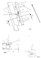
- Fig. 1 shows a highly schematic three-dimensional representation a sill 1 of a motor vehicle and one thereon Adjacent seat rail 2.
- the seat rail 2 is on a seat base 3 fixed with a vehicle floor, not shown connected to the motor vehicle and runs in the longitudinal direction of the vehicle of the motor vehicle.
- the seat rail 2 is with a further parallel seat rail for accommodating a passenger seat (not shown) provided, which in the installed position the two seat rails 2 is slidably mounted.
- Safety device 4, 5 provided in the longitudinal direction of the motor vehicle are arranged at a distance from one another and can be brought into operative connection with one another in such a way that over the safety devices 4, 5 at a high dynamic Load on the passenger seat and / or the sill 1 one Connection between the sill 1 and the seat rail 2 made becomes.
- a high dynamic load can be caused, for example, by a Rear and / or front impact (crash) of the motor vehicle caused be and a relative movement between the seat rail 2 and the sill 1, through which the safety device 4 of the seat rail 2 and the safety device 5 the sill 2 are brought into contact with each other.
- a Rear and / or front impact (crash) of the motor vehicle caused be and a relative movement between the seat rail 2 and the sill 1, through which the safety device 4 of the seat rail 2 and the safety device 5 the sill 2 are brought into contact with each other.
- the safety device has 4 of the seat rail 2 is a hook-shaped catch plate 6 on, which is provided with a recess and with the Seat rail 2 is welded.
- the safety device 5 of the Sill 1 has a bolt or pin 7 which is connected to the Sill 1 is welded and installed in the area of Recess of the hook-shaped catch plate 6 is arranged without touching it.
- a crash case can lead to deformation of the bodywork Motor vehicle and a displacement of the seat rail 2 lead essentially in the longitudinal direction of the motor vehicle, the bolt 7 on the hook-shaped catch plate 6 in the area the recess comes to rest almost form-fitting.
- Fig. 2 is a view of the sill 1 and the seat rail 2 shown in section along the line II-II in Fig. 1.
- the Length of the bolt 7 is provided such that it differs from that Sill 1 starting from the recess of the hook-shaped Catch plates 6 and extends beyond this. This ensures that the connection between the seat rail 2 and the sill 1 even with severe deformations of the body of the motor vehicle, in particular also the vehicle floor of the motor vehicle and the sill 1, due to a The bolt 7 slides out of the engagement of the hook-shaped Catch plate 6 is not solved.
- the bolt 7 is in the forward direction of the motor vehicle, which is indicated in Fig. 1 by an arrow, in front of the hook-shaped Arrester plate 6 arranged so that a movement of the Seat rail 2 is blocked in the forward direction. Thereby in the event of a crash, the passenger's seat is shifted and a resulting possible injury to passengers avoided.
- the sill 1 is in the vertical direction the bolt 7 and the hook-shaped catch plate 6 on the seat rail 2, which has a high bending stiffness. This is a deformation of the rocker 1, such as Buckling in the event of a crash, thanks to the additional support and stiffening of the body counteracted.
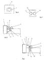
- a catch plate 8 is shown with an opening 9, in which the bolt 7 engages.
- the catch plate 8 can instead the hook-shaped catch plate 7 attached to the seat rail 2 be, with a movement of the seat rail 2 not only in the forward direction of the motor vehicle but also in opposite Direction opposite the sill 2 is limited. Also in this case the bolt 7 and the catch plate 8 are normal Installation position, i.e. before a crash, spaced apart arranged.
- Fig. 5 shows a further double-hook-shaped catch plate 10 of the safety device 4 of the seat rail 2, which has a recess on each of its end faces, in the first, in the longitudinal direction of the motor vehicle in front of the double-hook-shaped catch plate 10 arranged bolts 11 and one arranged in the longitudinal direction behind the catch plate 10 second bolt 12 of the safety device 5 of the Sills 1 engages.
- FIG. 4 and FIG. 5 common that the sill 1 in the event of a crash in vertical Direction is supported by the seat rail 2 and one Stiffening the body of the motor vehicle passive safety elevated.
- the safety device 5 of the sill 1 have a crash console 13, which with the sill 1 and the bolt 7 is connected, the Bolt 7 in its length beyond the crash console 13 extends that it is in the recess of the hook-shaped catch plate 6 engages.
- the bolt 7 is with the sill 1 and in the area in front of the Engagement in the hook-shaped catch plate 6 with the crash console 13 connected. So that a fixed receptacle of the bolt 7 in the crash console 13 ensures.
- the crash console 13 is a pocket-like stamped and bent part or hollow part and at least with the sill 1 welded in sections.
- the crash console 13 Due to the special design of the crash console 13 as Hollow part, it has a high stability for the transmission of Forces between the seat rail 2 and the sill 1 across Longitudinal axis of the motor vehicle and thus provides side impact protection represents.
- a sleeve 16 is arranged, which itself from a leg 17 of the U-shaped section 15 the recess of the hook-shaped catch plate 6 through up to a second leg 18 of section 15 extends.
- the sleeve 16 is welded to the two legs 17, 18 and engages with a displacement of the seat rail 2 the sill 1 in the forward direction in the hook-shaped Catch plate 6, creating a connection between the sill 1 and the seat rail 2 made over the sheet steel part 14 is.
- This is the stiffening of the body of the motor vehicle increased and a deformation of the rocker 1 at one Crash case avoided by vertical support on the seat rail 2.
- the sheet steel part 14 at a Accident forces across the longitudinal axis of the motor vehicle from the Transfer sill 1 to the seat rail 2, which makes it also suitable as side impact protection.
- the bolts 7, 11, 12, the catch plates 6, 8, 10, the crash console 13 and the sheet steel part 14 instead one weld also another for the application suitable connection, such as screw connection, connected to the sill 1 or the seat rail 2 his.
- the catch plates 6, 8, 10 also in one piece with the Train seat rail 2 or the sill 1.
Landscapes
- Engineering & Computer Science (AREA)
- Aviation & Aerospace Engineering (AREA)
- Transportation (AREA)
- Mechanical Engineering (AREA)
- Seats For Vehicles (AREA)
- Body Structure For Vehicles (AREA)
Applications Claiming Priority (2)
| Application Number | Priority Date | Filing Date | Title |
|---|---|---|---|
| DE19910086 | 1999-03-08 | ||
| DE19910086A DE19910086C2 (de) | 1999-03-08 | 1999-03-08 | Kraftfahrzeug mit Fahrzeugsitz |
Publications (2)
| Publication Number | Publication Date |
|---|---|
| EP1034971A2 true EP1034971A2 (fr) | 2000-09-13 |
| EP1034971A3 EP1034971A3 (fr) | 2002-07-24 |
Family
ID=7900073
Family Applications (1)
| Application Number | Title | Priority Date | Filing Date |
|---|---|---|---|
| EP00102037A Withdrawn EP1034971A3 (fr) | 1999-03-08 | 2000-02-02 | Siège de véhicule automobile |
Country Status (3)
| Country | Link |
|---|---|
| US (1) | US6422631B1 (fr) |
| EP (1) | EP1034971A3 (fr) |
| DE (1) | DE19910086C2 (fr) |
Families Citing this family (8)
| Publication number | Priority date | Publication date | Assignee | Title |
|---|---|---|---|---|
| US6857698B2 (en) | 2003-02-21 | 2005-02-22 | Lear Corporation | Seat side impact resistance mechanism |
| US6869132B2 (en) * | 2003-03-18 | 2005-03-22 | General Motors Corporation | Cross-car beam systems |
| US6758516B1 (en) * | 2003-06-13 | 2004-07-06 | Ford Global Technologies, Llc | Automotive vehicle with enhanced lateral collision intrusion resistance |
| US6886884B2 (en) * | 2003-07-21 | 2005-05-03 | Daimlerchrysler Corporation | Reducing localized deflection in the body of a body-on-frame vehicle |
| US7281755B2 (en) * | 2004-12-07 | 2007-10-16 | Nissan Technical Center North America, Inc. | Vehicle support structure with floor impact movement restriction device |
| JP4380565B2 (ja) * | 2005-03-10 | 2009-12-09 | トヨタ自動車株式会社 | 側突荷重伝達構造 |
| US7311169B1 (en) | 2005-09-22 | 2007-12-25 | Ford Global Technologies, Llc | Door system for automotive vehicle |
| US9758192B2 (en) * | 2015-05-11 | 2017-09-12 | Ford Global Technologies, Llc | Underbody structure for absorbing energy to improve roof structure integrity during side impact |
Citations (3)
| Publication number | Priority date | Publication date | Assignee | Title |
|---|---|---|---|---|
| DE7932187U1 (de) | 1978-11-20 | 1980-02-14 | Brandoli, Luigi, Turin (Italien) | Quertraeger zur verbindung der beiden beweglichen laengsfuehrungen eines fahrzeugsitzes miteinander |
| EP0046227A2 (fr) | 1980-08-14 | 1982-02-24 | Nissan Motor Co., Ltd. | Siège de véhicule à arrêteur de portière |
| DE4102353A1 (de) | 1991-01-26 | 1992-07-30 | Audi Ag | Personenkraftwagen mit seitlichen tuerschwellern |
Family Cites Families (12)
| Publication number | Priority date | Publication date | Assignee | Title |
|---|---|---|---|---|
| DE2747584A1 (de) * | 1977-10-24 | 1979-04-26 | Keiper Automobiltechnik Gmbh | Traegheitssperreinrichtung fuer kraftfahrzeugsitze |
| DE2953352A1 (de) * | 1979-04-24 | 1980-12-04 | Brose & Co Metallwerk Max | Vorrichtung zur schnellbefestigung einer vorzugsweise elektrischen sitzverstelleinrichtung am fahrzeugboden eines kraftfahrzeugs und/oder eines sitzes an der sitzverstelleinrichtung |
| JPS6223324Y2 (fr) * | 1980-11-07 | 1987-06-13 | ||
| DE3624295A1 (de) * | 1986-07-18 | 1988-01-21 | Keiper Recaro Gmbh Co | Rueckenlehnenrahmen fuer sitze, insbesondere fuer kraftfahrzeugsitze |
| DE4024838C2 (de) * | 1990-08-04 | 1996-05-23 | Audi Ag | Sitz für Fahrzeuge |
| US5584525A (en) * | 1993-03-03 | 1996-12-17 | Nissan Motor Co., Ltd. | Automotive seat having robust construction |
| JP3637141B2 (ja) * | 1996-03-19 | 2005-04-13 | 富士重工業株式会社 | 車両車体の側面衝突対策構造 |
| US6050629A (en) * | 1996-09-24 | 2000-04-18 | Lear Corporation | Vehicle seat having combined horizontal and vertical frame mounting system |
| TW556692U (en) * | 1997-01-31 | 2003-10-01 | Mazda Motor | Body structure for vehicle |
| DE19709314C2 (de) * | 1997-03-07 | 1998-11-19 | Audi Ag | Sitzuntergestell für einen Kraftfahrzeugsitz |
| FR2776581B1 (fr) * | 1998-03-24 | 2000-06-02 | Faure Bertrand Equipements Sa | Glissiere pour siege de vehicule et siege comportant une telle glissiere |
| JP3539197B2 (ja) * | 1998-04-08 | 2004-07-07 | 日産自動車株式会社 | 自動車のフロア部車体構造 |
-
1999
- 1999-03-08 DE DE19910086A patent/DE19910086C2/de not_active Expired - Fee Related
-
2000
- 2000-02-02 EP EP00102037A patent/EP1034971A3/fr not_active Withdrawn
- 2000-03-08 US US09/520,975 patent/US6422631B1/en not_active Expired - Fee Related
Patent Citations (3)
| Publication number | Priority date | Publication date | Assignee | Title |
|---|---|---|---|---|
| DE7932187U1 (de) | 1978-11-20 | 1980-02-14 | Brandoli, Luigi, Turin (Italien) | Quertraeger zur verbindung der beiden beweglichen laengsfuehrungen eines fahrzeugsitzes miteinander |
| EP0046227A2 (fr) | 1980-08-14 | 1982-02-24 | Nissan Motor Co., Ltd. | Siège de véhicule à arrêteur de portière |
| DE4102353A1 (de) | 1991-01-26 | 1992-07-30 | Audi Ag | Personenkraftwagen mit seitlichen tuerschwellern |
Also Published As
| Publication number | Publication date |
|---|---|
| EP1034971A3 (fr) | 2002-07-24 |
| DE19910086A1 (de) | 2000-09-21 |
| US6422631B1 (en) | 2002-07-23 |
| DE19910086C2 (de) | 2002-11-28 |
Similar Documents
| Publication | Publication Date | Title |
|---|---|---|
| EP0608558B1 (fr) | Cellule pour les passagers avec renforcement transversal dans la zone des sièges | |
| DE3023035A1 (de) | Fahrzeugsitz, insbesondere fuer kraftfahrzeuge | |
| EP2608988B1 (fr) | Dispositif de blocage d'un appui-tête | |
| EP1140556A1 (fr) | Siege de vehicule a systeme de reglage en hauteur | |
| DE102020106821B4 (de) | Sitzträgerstruktur für einen Fahrzeugsitz und Fahrzeugsitz | |
| EP1897761A2 (fr) | Véhicule automobile doté d'un dispositif d'arceau de capote | |
| DE3144218A1 (de) | Tueranschlagvorrichtung fuer ein fahrzeug | |
| DE102006047626B4 (de) | Sitzschiene für Fahrzeuge | |
| DE102008022564A1 (de) | Querträgeranordnung für einen Kraftwagen | |
| DE19910086C2 (de) | Kraftfahrzeug mit Fahrzeugsitz | |
| DE2142609A1 (de) | Vorrichtung zum gegenseitigen Verriegeln zweier gegeneinander verschiebbarer Bauelemente | |
| DE102004008647B4 (de) | Anordnung eines Bremskraftverstärkers in einem Fahrzeug, insbesondere einem Kraftfahrzeug | |
| DE10119131A1 (de) | Fahrzeugtür mit einer Crashabstützung | |
| EP4522446B1 (fr) | Ensemble rail pour système de réglage de siège longitudinal d'un siège de véhicule | |
| EP1615795B1 (fr) | Dispositif de guidage longitudinal pour un siege de vehicule automobile | |
| DE102004062629A1 (de) | Abdeckung an einem Vorderwagen eines Fahrzeuges | |
| EP1517814B1 (fr) | Structure porteuse a pare-chocs de vehicule automobile | |
| DE102021004411A1 (de) | Fahrzeugtür mit einem Seitenaufprallschutzsystem | |
| DE102004025504B4 (de) | Verriegelung für einen Sitzlängsversteller | |
| DE102011118152A1 (de) | Lagerung eines Funktionselements in einem Schienenpaar innerhalb eines Fahrgastraums eines Kraftfahrzeugs | |
| EP2566726B1 (fr) | Dispositif de cadre pour une structure de protection contre le renversement et structure de protection contre le renversement comportant un dispositif de cadre | |
| DE102005028962B4 (de) | Überrollschutzsystem mit Rasteinrichtung für ein Kraftfahrzeug | |
| DE102006039032B4 (de) | Stützanordnung für eine Kraftwagenkarosserie | |
| DE10354164B4 (de) | Transportbehälter-Einrichtung für Fahrzeuge | |
| DE102005028963B4 (de) | Überrollschutzsystem mit Rasteinrichtung für ein Kraftfahrzeug, insbesondere für ein Cabriolet |
Legal Events
| Date | Code | Title | Description |
|---|---|---|---|
| PUAI | Public reference made under article 153(3) epc to a published international application that has entered the european phase |
Free format text: ORIGINAL CODE: 0009012 |
|
| AK | Designated contracting states |
Kind code of ref document: A2 Designated state(s): AT BE CH CY DE DK ES FI FR GB GR IE IT LI LU MC NL PT SE |
|
| AX | Request for extension of the european patent |
Free format text: AL;LT;LV;MK;RO;SI |
|
| PUAL | Search report despatched |
Free format text: ORIGINAL CODE: 0009013 |
|
| AK | Designated contracting states |
Kind code of ref document: A3 Designated state(s): AT BE CH CY DE DK ES FI FR GB GR IE IT LI LU MC NL PT SE |
|
| AX | Request for extension of the european patent |
Free format text: AL;LT;LV;MK;RO;SI |
|
| RIC1 | Information provided on ipc code assigned before grant |
Free format text: 7B 60N 2/42 A |
|
| 17P | Request for examination filed |
Effective date: 20020614 |
|
| STAA | Information on the status of an ep patent application or granted ep patent |
Free format text: STATUS: THE APPLICATION IS DEEMED TO BE WITHDRAWN |
|
| 18D | Application deemed to be withdrawn |
Effective date: 20020903 |