EP1034978A2 - Dispositif de fixation d'une bicyclette à l'intérieur d'un véhicule - Google Patents
Dispositif de fixation d'une bicyclette à l'intérieur d'un véhicule Download PDFInfo
- Publication number
- EP1034978A2 EP1034978A2 EP00104313A EP00104313A EP1034978A2 EP 1034978 A2 EP1034978 A2 EP 1034978A2 EP 00104313 A EP00104313 A EP 00104313A EP 00104313 A EP00104313 A EP 00104313A EP 1034978 A2 EP1034978 A2 EP 1034978A2
- Authority
- EP
- European Patent Office
- Prior art keywords
- holding
- seat back
- holding part
- headrest
- holding means
- Prior art date
- Legal status (The legal status is an assumption and is not a legal conclusion. Google has not performed a legal analysis and makes no representation as to the accuracy of the status listed.)
- Granted
Links
- 210000000078 claw Anatomy 0.000 claims description 12
- 230000000149 penetrating effect Effects 0.000 claims description 4
- 230000003319 supportive effect Effects 0.000 claims 1
- 210000002414 leg Anatomy 0.000 description 7
- 230000036316 preload Effects 0.000 description 3
- 238000005553 drilling Methods 0.000 description 2
- 229910000831 Steel Inorganic materials 0.000 description 1
- 230000006978 adaptation Effects 0.000 description 1
- 238000005452 bending Methods 0.000 description 1
- 238000009434 installation Methods 0.000 description 1
- 239000010959 steel Substances 0.000 description 1
- 210000000689 upper leg Anatomy 0.000 description 1
Images




Classifications
-
- B—PERFORMING OPERATIONS; TRANSPORTING
- B60—VEHICLES IN GENERAL
- B60R—VEHICLES, VEHICLE FITTINGS, OR VEHICLE PARTS, NOT OTHERWISE PROVIDED FOR
- B60R11/00—Arrangements for holding or mounting articles, not otherwise provided for
-
- B—PERFORMING OPERATIONS; TRANSPORTING
- B60—VEHICLES IN GENERAL
- B60R—VEHICLES, VEHICLE FITTINGS, OR VEHICLE PARTS, NOT OTHERWISE PROVIDED FOR
- B60R5/00—Compartments within vehicle body primarily intended or sufficiently spacious for trunks, suit-cases, or the like
-
- B—PERFORMING OPERATIONS; TRANSPORTING
- B62—LAND VEHICLES FOR TRAVELLING OTHERWISE THAN ON RAILS
- B62H—CYCLE STANDS; SUPPORTS OR HOLDERS FOR PARKING OR STORING CYCLES; APPLIANCES PREVENTING OR INDICATING UNAUTHORIZED USE OR THEFT OF CYCLES; LOCKS INTEGRAL WITH CYCLES; DEVICES FOR LEARNING TO RIDE CYCLES
- B62H3/00—Separate supports or holders for parking or storing cycles
Definitions
- the invention relates to a device for fastening a bicycle on a seat back of a motor vehicle, with one to be attached to the seat back Holding part and with a arranged on the holding part, holding element provided for fastening the bicycle.
- Such a facility is out, for example known from DE 42 08 064 C2.
- This facility has one Flange plate provided for attachment to the rear seat backrest.
- the flange plate points to the implementation of fasteners provided holes.
- the fasteners are used to screw the flange plate with a back of the back seat.
- a disadvantage of this facility is that the attachment of the Flange plate on the seat back designed very complex. For this, the seat back is in accordance with the holes in the Drill the flange plate.
- the facility is often said to Disassembled regularly when not in use. Therefore be rivet nuts are placed in the back of the seat, with which the Flange plate can be screwed. When drilling into the There is also a risk of upholstery on the back of the seat the rear seat backrest and a cover can be damaged.
- brackets for the transport of bicycles known inside the vehicle have a holding device for an axle mount of the front fork of the Bicycle.
- These holding devices each have one Flange plate for screwing to that of the seat back or with the vehicle floor.
- the invention is based on the problem of a To design the facility of the type mentioned at the beginning that they are particularly easy to assemble in motor vehicles and is removable.
- this problem is solved by that the holding part for fastening in the area of a Headrest bracket for the seat back and / or in the area one for connection to a closing part of the body provided locking of the seat back of the motor vehicle is designed.
- the holding part is required no flange plate to be screwed to the back of the seat. Drilling the back of the seat is not thanks to the invention required. This will damage the upholstery of the seat reliably avoided.
- the facility is therefore particularly easy to install in motor vehicles and removable. Because the holding part is special anyway stable areas of the seat is attached, the holding part can be particularly high when assembled Absorb holding forces.
- the holding part can also with appropriate Design for mounting in a vertical or horizontal position of the seat back provided his.
- the holding part for attachment to the headrests with the seat back handrails to be connected or in the handrails leading headrest sleeves provided for the seat back Holding means and means for its support on one has rear area of the seat back.
- the holding part is particularly easy Secure accessible parts of the seat.
- the handrails have the headrests a grid, in the locking means of the headrest sleeve intervention.
- an unlock button on the headrest sleeve intended.
- you press the release button are the locking means from the grid of the handrail away.
- the assembly and the disassembly of the device according to the invention in particular easy if the holding means one in a headrest sleeve the seat back for the handrails of the headrests have a locking latch.
- the unlocking button can be operated and the headrest simply against the holding means change.
- the holding part is according to an advantageous Further development of the invention reliably in its intended Positioned when the holding means is a tab with one according to the dimensions of the handrails the headrest have a designed bore.
- the tab of the device according to the invention is simple clamped between the seat back and the headrest.
- the holding means are designed according to another advantageous development of the invention constructively particularly easy if the holding means one for lateral gripping of the handrail provided fork-shaped To have a claw.
- the claw can be in the grid the handrail for the headrest.
- the device according to the invention can be easy on backrests with non-removable headrests fasten if two claws each to grasp a handrail pointing towards or away from each other are arranged.
- the device according to the invention can be used particularly low effort for any motor vehicle convert if the holding means have an angle and attached to the holding part as a separate component are.
- the holding part can be used as a standard component be designed for all motor vehicles while adapting the different dimensions of the backrests the holding means are replaced.
- An adaptation of the device according to the invention designed to different dimensions of headrests is particularly easy if the holding means each are arranged in pairs on the holding part and the Distance of the holding means to one another is adjustable.
- each bike In the known facilities for each bike to be carried on its own flange plate screwed onto the back of the seat. Here are the positions the bicycles from those arranged in the back of the seat Holes permanently fixed.
- the bike or however, several bikes can be made according to another advantageous development of the invention optionally comfortable in a medium range or space saving in arrange a side area of the motor vehicle, if the holding part is transverse to the direction of travel of the motor vehicle mountable guide rail for sliding Holding at least one holding element.
- the attachment of the holding part to the handrail is designed according to another advantageous Further development of the invention is particularly cost-effective if the holding means a split pin for fastening the holding part on the handrail. This cotter pin can do it naturally snap into the grid of the handrail.
- the assembly of the device according to the invention is particularly comfortable when the holding means a leg spring with a grid in the handlebar penetrating thigh.
- the holding part can be made according to another advantageous training reliably with the seat back brace when there is an adjustable screw for pre-tensioning against the back of the seat back provided plate.
- the body of the motor vehicle has the device according to the invention particularly high holding forces record if the holding part at least one corresponding to one of the locks of the seat back Has locking part.
- the locks are on the seat back does not require any adjustments to the holding part, since the locks in the folded state of the Seat back are freely accessible anyway.
- the locks are the locks as a fork latch operated by a lever designed.
- the striker can be simple as a latch or bracket that can be gripped by the fork latch be designed.
- the holding part is according to an advantageous Further development of the invention reliably on the seat back attached when the holding part extends over the entire Width of the seat back extends and at its ends each has a locking part.
- the invention Setup for multiple bikes also at A reliable lateral cornering of the motor vehicle Guide.
- An intended position of the guide rail depending on the position of the latches of the Seat back can be according to an advantageous development simply define the invention if at least one the ends of the guide rail attached in a side part and if the closing part is on the side part is arranged.
- the handling of the device according to the invention is particularly comfortable when the holding element designed to be lockable on the guide rail is.
- the bike can be initially in the middle Attach the area of the motor vehicle to the holding elements and then into a space-saving side Move position.
- the device according to the invention is designed structurally particularly simple if the holding element on designed to support a back seat back of the seat back is.
- the lock can be used Simply avoid further development of the invention if the locking part is mushroom-shaped.
- the locking part can simplify its Alignment can be adjusted relative to the lock.
- Figure 1 shows a mounted on a seat back 1 Device with a holding part 2 and with one Holding element 3 for holding a not shown Bicycle.
- the seat back 1 has one on handrails 4 arranged headrest 5.
- the headrest 5 can be in adjust the height in relation to the seat back 1 and by it separate.
- the handrails 4 are each with grids 6 provided.
- a holding means 7 is on the holding part 2 arranged to the support rods 4 angled tabs 8.
- the tabs 8 have holes 9 for performing the Handrails 4 on.
- the holding element 3 has a fork mounting pin 10 for one Front fork of the bicycle. On the fork pin 10 there is also a quick-action fastener 11, with which the bike can be easily assembled.
- the holding element 3 By this design of the holding element 3 is the seat back 1 before attaching the bike to the horizontal position to pan. Furthermore, the holding element 3 a set screw 12 with which its distance from each other the seat back 1 can be adjusted.
- the holding part 3 is supported on the back of the seat back.
- the Tabs 8 are screwed to the holding element 3, so that they vary according to the dimensions and arrangement the handrails 4 of the headrests 5 are easy to design and have it exchanged.
- FIG. 2 shows a further embodiment of the Device in which a holding part 13 holding means 14 with penetrating into the headrest sleeves 15 of the seat back 1 Has locking bars 16.
- the headrest sleeves 15 are after disassembly of the headrest 5 shown in FIG. 1 accessible.
- the locking bars 16 are like those in FIG. 1 illustrated handrails 4 of the headrest 5 designed and have a grid 17. In the grid 17 engage within the headrest sleeves 15, of unlocking buttons 18 operable locking means. To simplify the drawing, the locking means are not shown.
- the holding part 13 can thus be a Press the unlocking buttons 18 from the seat back 1 remove.
- the locking bars 16 each a bend 19 with which it is screwed to side parts 20 is.
- the locking bars 16 also be welded to the side parts 20 so that they absorb bending forces introduced via the holding element 3 can.
- the holding part 3 is supported on the back the seat back.
- FIG 3 shows one in the horizontal Position swiveled seat back 1 mounted further embodiment the establishment.
- the facility has one on one of the support rods 4 of the headrest 5 and in a locking part 21 of the seat back supporting holding part 22.
- the holding part 22 has holding means 23 with a the handrail 4 gripping laterally and fork-shaped designed claw 24. Furthermore, the holding part 22 a locking part corresponding to the lock 21 25.
- the latch 21 is used to seat 1 in a vertical position with a not shown Locking part of the body of the motor vehicle connect. In the horizontal position shown the seat back 1, the lock 21 is freely accessible.
- On the seat back 1 is an actuator 26 for Open the latch 21 arranged.
- the holding part 22 carries a holding element 27 with support rods 28 for mounting a frame tube of the bicycle.
- the support rods 28 have one of a clamping screw at their free ends 29 adjustable clamping fist 30.
- FIG. 4 shows another one on the seat back 1 attach embodiment of the device with several holding elements 32 arranged on a holding part 31 34 for one bike each.
- the seat back 1 is part here a back seat and in a horizontal position on one Seat cushion 35 pivoted.
- the holding part 31 has holding means 39 with opposing pairs Claws 40, 41. Claws 40, 41 are against the two outer pairs of support rods 36, 38 biased.
- the holding part 31 has one over the entire Width of the seat back 1 extending guide rail 42 for slidable and lockable mounting of the Holding elements 36-38.
- the holding elements 36-38 have to support on the back of the seat back 1 each Support feet 43.
- FIG. 5 shows one arranged on a holding element 44 Set screw 45 for adjusting the holding element 44 on the back of the seat back 1 Tellers 46.
- the holding element 44 carries on its top an example of a holding arm 47 for a front wheel of the bike.
- the holding element 44 can, for example, on the holding part 22 shown in Figure 3 are attached. This can be done by adjusting Locking part 25 of the holding part 22 in the lock 21 preload.
- this support can be mounted on the seat back 1 simplify and movements of the holding means 7, 14 opposite the handrails 4 or the headrest sleeves 15 avoid.
- FIG. 6 shows a holding element 49 with a Tension lever 51 non-rotatably connected to an eccentric 50.
- the tension lever 51 has a bearing 52 in the holding element 49.
- the eccentric 50 biased against the back of the seat back.
- On the holding element 49 has brackets 53 on its upper side for the bike on. The holding element 49 can thus be used use as the holding element 44 shown in Figure 5.
- Figure 7 shows a split pin 54 to secure a designed as a claw holding means 55 on the support rod 4.
- the split pin 54 engages in a grid 6 Holding rod 4, so that the holding means 55 against one Movement along the support rod 4 is secured.
- the claw-shaped holding means 55 can also the tabs 8 shown in Figure 1 with the Splint 54 are secured. The can be dismantled Simply pull off the split pin 54 from the handrail 4.
- Figure 8 shows a fuse as a claw trained holding means 55 by means of a leg spring 57.
- the leg spring 57 is with a leg 58 connected to the holding means 55.
- With a second leg 59 latches the leg spring 57 in the grid 6 of the Handrail 4 a.
- FIG. 9 schematically shows an interior of a Motor vehicle in a top view with two front Sit 101, 102 and with a back seat 103.
- the Rear seat bench 103 has one at right angles to the direction of travel of the motor vehicle arranged pivot axis A to the front folded seat back 104 with two backrest parts 105, 106.
- the backrest parts 105, 106 can be folded down individually.
- On the seat back 104 is a device with a holding part 107 attached for a total of two bicycles. For simplification the drawing shows the bicycles in FIG. 9 not shown.
- the holding part 107 has two guide rails 108, 109 with two on the guide rails 108, 109 holding elements 110, 111 guided in a longitudinally displaceable manner for one bike at a time.
- the holding elements 110, 111 can be placed in a designated position on the guide rails 108, 109 determine.
- the guide rails 108, 109 here extend over the entire width of the Seat back 104 and are
- Mushroom-shaped locking parts are in the motor vehicle 114, 115 attached.
- the closing parts 114, 115 of the motor vehicle from arranged on the seat back 104 Locks 116, 117 held.
- To release the locks 116, 117 are at the free end of the seat back 104 actuators 118, 119 are arranged.
- the holding part 107 has one on the side parts 112, 113 attached, in the locks 116, 117 engaging strikers 120, 121.
- strikers 120, 121 are like the locking parts 114, 115 of the motor vehicle designed.
- the holding part 107 becomes reliable connected to the seat back 104.
- the actuators 118, 119 operated For releasing the holding part 107 from the seat back 104 become the actuators 118, 119 operated.
- FIG. 10 shows a partial area in perspective of the holding part 107 with the seat back 104 from Figure 9 in Area of one of the holding elements 111.
- the holding element 111 has a fork pin 122 and support rods 123 to hold a bicycle 124.
- the support rods 123 have an adjustable by a clamping screw 125 Clamping fist 126 for holding a frame tube 127 of the Bicycle 124 on.
- the fork mounting pin 122 can be one not shown, known from front wheel axles Have quick release fastener.
- the seat back 104 is made of sheet steel Has rear seat back 128 and padding 129.
- the holding element 111 has support feet 130 for support on the rear seat back 128.
- additional facilities for example to hold a front wheel of the Bicycle 124, may be arranged.
- Figure 11 shows one of a set screw 131 adjustable, for supporting a holding element 132 on the rear seat back 128 designed plate 133.
- Die Set screw 131 has a thread 134 for adjusting the Plates 133 opposite the holding element 132.
- the holding element 132 carries an example on its top Support arm 135 for a front wheel 136 of the shown in Figure 10 Bicycle 124.
- the preload ensures that the figure 9 shown locking parts 120, 121 of the holding part are biased in the locks 116, 117.
- the plate 133 forms a counter bearing for the locking 116, 117, so with an appropriate design the lock 116, 117 the establishment of only one the locking parts 120, 121 needed.
- This allows for the transportation of a single bicycle be provided with appropriate dimensions and only one of the backrest parts 105, 106 shown in FIG. 9 the seat back 104 are folded.
- the holding element 132 can additionally add the seat back 104 reach around its attachment in the intended position ensure.
- Figure 12 shows a rotationally fixed with an eccentric 137 connected tensioning lever 138.
- the tensioning lever 138 has a bearing 139 in a holding element 140 Rotation of the clamping lever 138 is the eccentric 137 against the rear seat back 128 biased.
- the holding element 140 On its top the holding element 140 has brackets 141 for the in figure 10 illustrated bicycle 124.
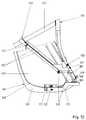
- FIG. 13 shows a perspective view of the one in FIG mounted a horizontal position pivoted seat back 104 further embodiment of the device.
- the facility has one on a handrail 142 one Headrest 143 and in a lock 144 of the seat back supporting holding part 145.
- the holding rod 142 is displaceable in a headrest sleeve 156 of the seat back 104 guided.
- the holding part 145 has holding means 146 with a side grip around the holding rod 142 Claw 147 on.
- the holding part 145 has a the locking part 148 corresponding to the lock 144.
- This lock 144 serves to seat back 104 in a vertical position with that shown in Figure 9 Locking part 121 of the body of the motor vehicle connect.
- the Holding part 145 carries a holding element 150 with support rods 151 for holding a frame tube of the bicycle.
- the Support rods 151 have one of one at their free ends
- Clamping screw 152 adjustable clamping fist 153 fork receiving bolt arranged on the holding element 150 154 has a quick release lock 155.
Landscapes
- Engineering & Computer Science (AREA)
- Mechanical Engineering (AREA)
- Seats For Vehicles (AREA)
- Chair Legs, Seat Parts, And Backrests (AREA)
Applications Claiming Priority (4)
| Application Number | Priority Date | Filing Date | Title |
|---|---|---|---|
| DE19909606 | 1999-03-05 | ||
| DE1999109606 DE19909606B4 (de) | 1999-03-05 | 1999-03-05 | Einrichtung zur Befestigung eines Fahrrades |
| DE1999109603 DE19909603C5 (de) | 1999-03-05 | 1999-03-05 | Einrichtung zur Befestigung eines Fahrrades |
| DE19909603 | 1999-03-05 |
Publications (4)
| Publication Number | Publication Date |
|---|---|
| EP1034978A2 true EP1034978A2 (fr) | 2000-09-13 |
| EP1034978A3 EP1034978A3 (fr) | 2003-03-19 |
| EP1034978B1 EP1034978B1 (fr) | 2005-01-26 |
| EP1034978B2 EP1034978B2 (fr) | 2008-08-27 |
Family
ID=26052198
Family Applications (1)
| Application Number | Title | Priority Date | Filing Date |
|---|---|---|---|
| EP00104313A Expired - Lifetime EP1034978B2 (fr) | 1999-03-05 | 2000-03-02 | Dispositif de fixation d'une bicyclette à l'intérieur d'un véhicule |
Country Status (3)
| Country | Link |
|---|---|
| EP (1) | EP1034978B2 (fr) |
| DE (1) | DE50009318D1 (fr) |
| ES (1) | ES2235700T5 (fr) |
Cited By (1)
| Publication number | Priority date | Publication date | Assignee | Title |
|---|---|---|---|---|
| DE102024127891A1 (de) * | 2024-09-26 | 2026-03-26 | Dr. Ing. H.C. F. Porsche Aktiengesellschaft | Stützbügel für ein lademanagement in einem gepäckraum eines personenkraftwagens |
Families Citing this family (2)
| Publication number | Priority date | Publication date | Assignee | Title |
|---|---|---|---|---|
| DE102011010579A1 (de) | 2011-02-08 | 2012-08-09 | GM Global Technology Operations LLC (n. d. Gesetzen des Staates Delaware) | Vorrichtung zur Befestigung eines Fahrrades in einem Fahrzeuginnenraum |
| DE102011010577A1 (de) | 2011-02-08 | 2012-08-09 | GM Global Technology Operations LLC (n. d. Gesetzen des Staates Delaware) | Vorrichtung zur Befestigung eines Fahrrades in einem Fahrzeuginnenraum |
Citations (4)
| Publication number | Priority date | Publication date | Assignee | Title |
|---|---|---|---|---|
| DE4208064C2 (fr) | 1991-11-02 | 1993-08-12 | Dieter 6121 Sensbachtal De Ulrich | |
| DE4226845C2 (de) | 1991-09-04 | 1997-04-30 | Samsung Electronics Co Ltd | System zum Auslöschen von Störbildern bei der NTSC-Fernsehübertragung |
| DE19636977A1 (de) | 1995-12-22 | 1997-07-03 | Dieter Ulrich | Halterung für den Transport von Fahrrädern im Inneren eines Kraftfahrzeuges |
| DE29614632U1 (de) | 1996-08-23 | 1997-12-18 | Industri Ab Thule, Hillerstorp | Fahrradstütze |
Family Cites Families (12)
| Publication number | Priority date | Publication date | Assignee | Title |
|---|---|---|---|---|
| US4792183A (en) † | 1987-10-29 | 1988-12-20 | Townsend Iii William R | Desk for use in automobiles |
| DE4226945C2 (de) * | 1992-03-13 | 1994-08-11 | Dieter Ulrich | Halterung für den Transport von Fahrrädern im Kraftfahrzeuginnern |
| DE4222024A1 (de) * | 1992-07-04 | 1994-01-05 | Bayerische Motoren Werke Ag | Vorrichtung zum Befestigen eines Transportgegenstands im Laderaum eines Kraftfahrzeugs |
| DE4442027A1 (de) † | 1993-12-24 | 1995-06-29 | Volkswagen Ag | Stützelement |
| DE9412752U1 (de) * | 1994-08-06 | 1994-10-13 | Ulrich, Dieter, 64759 Sensbachtal | Halterung für den Transport von Fahrrädern im Kraftfahrzeuginnern |
| DE29508495U1 (de) * | 1995-05-22 | 1995-09-28 | Thevis, Paul, 78727 Oberndorf | Fahrradhalter für Pkw zum Transportieren von Fahrrädern |
| DE19544267A1 (de) † | 1995-11-28 | 1997-06-05 | Roland Drignath | Ausrüstung der Kopfstützen und Sitzlehnen insbesondere in Kraftfahrzeugen mit Einhänge- und Ablagevorrichtungen für Bekleidungsstücke, Schirme u. dgl. |
| DE19546543B4 (de) † | 1995-12-13 | 2007-10-04 | Edag Engineering + Design Ag | An einer hinsichtlich ihrer Neigung verstellbaren Rückenlehne eines Sitzes anzubringender Klapptisch |
| DE19612232B4 (de) † | 1996-03-27 | 2006-07-13 | Bayerische Motoren Werke Ag | Traggestell zur Abstützung von Gegenständen an einem Fahrzeugsitz eines Kraftfahrzeugs |
| DE29613480U1 (de) † | 1996-08-03 | 1996-09-26 | Bauer, Bernd, 79346 Endingen | Trägersystem zum stehenden Transport von Fahrrädern mit demontiertem Vorderrad im inneren von Kraftfahrzeugen, die über eine umklappbare Rücksitzbank verfügen |
| DE29613572U1 (de) † | 1996-08-06 | 1997-01-16 | Schachtner, Gerhard, 83104 Tuntenhausen | Halterung zum Transport von sperrigen Geräten, insbesondere von Fahrrädern, im Inneren von großraumigen Pkw |
| DE19751897B4 (de) † | 1996-11-29 | 2005-09-22 | Volkswagen Ag | Rückenstützelement |
-
2000
- 2000-03-02 EP EP00104313A patent/EP1034978B2/fr not_active Expired - Lifetime
- 2000-03-02 ES ES00104313T patent/ES2235700T5/es not_active Expired - Lifetime
- 2000-03-02 DE DE50009318T patent/DE50009318D1/de not_active Expired - Lifetime
Patent Citations (4)
| Publication number | Priority date | Publication date | Assignee | Title |
|---|---|---|---|---|
| DE4226845C2 (de) | 1991-09-04 | 1997-04-30 | Samsung Electronics Co Ltd | System zum Auslöschen von Störbildern bei der NTSC-Fernsehübertragung |
| DE4208064C2 (fr) | 1991-11-02 | 1993-08-12 | Dieter 6121 Sensbachtal De Ulrich | |
| DE19636977A1 (de) | 1995-12-22 | 1997-07-03 | Dieter Ulrich | Halterung für den Transport von Fahrrädern im Inneren eines Kraftfahrzeuges |
| DE29614632U1 (de) | 1996-08-23 | 1997-12-18 | Industri Ab Thule, Hillerstorp | Fahrradstütze |
Cited By (1)
| Publication number | Priority date | Publication date | Assignee | Title |
|---|---|---|---|---|
| DE102024127891A1 (de) * | 2024-09-26 | 2026-03-26 | Dr. Ing. H.C. F. Porsche Aktiengesellschaft | Stützbügel für ein lademanagement in einem gepäckraum eines personenkraftwagens |
Also Published As
| Publication number | Publication date |
|---|---|
| EP1034978A3 (fr) | 2003-03-19 |
| ES2235700T3 (es) | 2005-07-16 |
| EP1034978B1 (fr) | 2005-01-26 |
| DE50009318D1 (de) | 2005-03-03 |
| ES2235700T5 (es) | 2009-02-16 |
| EP1034978B2 (fr) | 2008-08-27 |
Similar Documents
| Publication | Publication Date | Title |
|---|---|---|
| AT502738B1 (de) | Kindersitzbefestigung und kinderrückhaltevorrichtung für kraftfahrzeuge | |
| DE19744978C2 (de) | Adapter | |
| DE4243826A1 (de) | Kraftfahrzeug mit mindestens einem Fahrzeugsitz und ein dazugehöriger Kindersitz | |
| DE10027063C2 (de) | Sitzmodul | |
| DE3878549T2 (de) | Vorrichtung zur sicherungsbefestigung eines kinderautositzes auf der hinteren sitzbank eines kraftfahrzeuges. | |
| EP2832628B1 (fr) | Objet d'équipement intérieur destiné à l'agencement dans des véhicules de transport public | |
| EP1481616B1 (fr) | Siège de bébé | |
| DE19909603B4 (de) | Einrichtung zur Befestigung eines Fahrrades | |
| EP3034404A1 (fr) | Siege | |
| DE102008029261A1 (de) | Sitzanordnung für ein Kraftfahrzeug mit einem abnehmbaren Zusatzsitz | |
| DE10303619A1 (de) | Kindersicherheitssitz zur Verwendung in einem Kraftfahrzeug | |
| DE19909606B4 (de) | Einrichtung zur Befestigung eines Fahrrades | |
| DE69502143T2 (de) | Vorrichtung zum Schnellverbinden eines Kindersitzes mit einem Kraftwagensitz | |
| DE102010026567B4 (de) | Trennbare und selbstschließende Sicherheitsspanneinrichtung für Kraftfahrzeuge | |
| DE4140638C2 (de) | Kindersicherheitssitz | |
| EP1034978B1 (fr) | Dispositif de fixation d'une bicyclette à l'intérieur d'un véhicule | |
| EP3597162B1 (fr) | Dispositif de fixation destiné à la fixation d'un fauteuil roulant | |
| EP3704009B1 (fr) | Remorque de bicyclette pour le transport de personnes avec au moins un dispositif de siège et un système de retenue par ceinture | |
| DE19841748A1 (de) | Motorrad mit Behältnis seitlich eines Soziussitzes | |
| EP0813992A2 (fr) | Siège d'enfant pour véhicules de transport de passagers | |
| DE102008017711A1 (de) | Kraftfahrzeugsitz mit einem Befestigungsmittel zur Befestigung eines Kindersitzes und Sitzanordnung mit einem solchen Kraftfahrzeugsitz | |
| DE19843870A1 (de) | Rückhaltesystem für in einem Fahrzeug mitgeführte, auf einem Sitzteil einer Rücksitzbank abgestellte Kindersitze | |
| DE4137576C2 (de) | Vorrichtung zur lösbaren Halterung von Gegenständen an einem Fahrzeugsitz | |
| EP0603520B1 (fr) | Siège de sécurité pour enfant | |
| DE102021209739A1 (de) | Sitzbaugruppe, Fahrzeug und Montageverfahren mit Zusatzteil für die Anbindung einer weiteren Komponente im Fahrzeuginnenraum |
Legal Events
| Date | Code | Title | Description |
|---|---|---|---|
| PUAI | Public reference made under article 153(3) epc to a published international application that has entered the european phase |
Free format text: ORIGINAL CODE: 0009012 |
|
| AK | Designated contracting states |
Kind code of ref document: A2 Designated state(s): AT BE CH CY DE DK ES FI FR GB GR IE IT LI LU MC NL PT SE |
|
| AX | Request for extension of the european patent |
Free format text: AL;LT;LV;MK;RO;SI |
|
| PUAL | Search report despatched |
Free format text: ORIGINAL CODE: 0009013 |
|
| AK | Designated contracting states |
Kind code of ref document: A3 Designated state(s): AT BE CH CY DE DK ES FI FR GB GR IE IT LI LU MC NL PT SE |
|
| AX | Request for extension of the european patent |
Extension state: AL LT LV MK RO SI |
|
| 17P | Request for examination filed |
Effective date: 20030812 |
|
| AKX | Designation fees paid |
Designated state(s): DE ES FR GB SE |
|
| GRAP | Despatch of communication of intention to grant a patent |
Free format text: ORIGINAL CODE: EPIDOSNIGR1 |
|
| GRAS | Grant fee paid |
Free format text: ORIGINAL CODE: EPIDOSNIGR3 |
|
| GRAA | (expected) grant |
Free format text: ORIGINAL CODE: 0009210 |
|
| AK | Designated contracting states |
Kind code of ref document: B1 Designated state(s): DE ES FR GB SE |
|
| REG | Reference to a national code |
Ref country code: GB Ref legal event code: FG4D Free format text: NOT ENGLISH |
|
| REG | Reference to a national code |
Ref country code: IE Ref legal event code: FG4D Free format text: GERMAN |
|
| REF | Corresponds to: |
Ref document number: 50009318 Country of ref document: DE Date of ref document: 20050303 Kind code of ref document: P |
|
| REG | Reference to a national code |
Ref country code: SE Ref legal event code: TRGR |
|
| GBT | Gb: translation of ep patent filed (gb section 77(6)(a)/1977) |
Effective date: 20050320 |
|
| REG | Reference to a national code |
Ref country code: ES Ref legal event code: FG2A Ref document number: 2235700 Country of ref document: ES Kind code of ref document: T3 |
|
| ET | Fr: translation filed | ||
| PLBI | Opposition filed |
Free format text: ORIGINAL CODE: 0009260 |
|
| PLAX | Notice of opposition and request to file observation + time limit sent |
Free format text: ORIGINAL CODE: EPIDOSNOBS2 |
|
| 26 | Opposition filed |
Opponent name: DAIMLERCHRYSLER AG Effective date: 20051026 |
|
| PLBB | Reply of patent proprietor to notice(s) of opposition received |
Free format text: ORIGINAL CODE: EPIDOSNOBS3 |
|
| RAP2 | Party data changed (patent owner data changed or rights of a patent transferred) |
Owner name: ADAM OPEL GMBH |
|
| PGFP | Annual fee paid to national office [announced via postgrant information from national office to epo] |
Ref country code: SE Payment date: 20080313 Year of fee payment: 9 |
|
| PUAH | Patent maintained in amended form |
Free format text: ORIGINAL CODE: 0009272 |
|
| STAA | Information on the status of an ep patent application or granted ep patent |
Free format text: STATUS: PATENT MAINTAINED AS AMENDED |
|
| 27A | Patent maintained in amended form |
Effective date: 20080827 |
|
| AK | Designated contracting states |
Kind code of ref document: B2 Designated state(s): DE ES FR GB SE |
|
| REG | Reference to a national code |
Ref country code: ES Ref legal event code: DC2A Date of ref document: 20081030 Kind code of ref document: T5 |
|
| REG | Reference to a national code |
Ref country code: GB Ref legal event code: 732E Free format text: REGISTERED BETWEEN 20090219 AND 20090225 |
|
| REG | Reference to a national code |
Ref country code: GB Ref legal event code: 732E Free format text: REGISTERED BETWEEN 20090305 AND 20090311 |
|
| REG | Reference to a national code |
Ref country code: GB Ref legal event code: 732E Free format text: REGISTERED BETWEEN 20091029 AND 20091104 |
|
| REG | Reference to a national code |
Ref country code: GB Ref legal event code: 732E Free format text: REGISTERED BETWEEN 20091105 AND 20091111 |
|
| REG | Reference to a national code |
Ref country code: DE Ref legal event code: R081 Ref document number: 50009318 Country of ref document: DE Owner name: GM GLOBAL TECHNOLOGY OPERATIONS LLC (N. D. GES, US Free format text: FORMER OWNER: GM GLOBAL TECHNOLOGY OPERATIONS, INC., DETROIT, US Effective date: 20110323 Ref country code: DE Ref legal event code: R081 Ref document number: 50009318 Country of ref document: DE Owner name: GM GLOBAL TECHNOLOGY OPERATIONS LLC (N. D. GES, US Free format text: FORMER OWNER: GM GLOBAL TECHNOLOGY OPERATIONS, INC., DETROIT, MICH., US Effective date: 20110323 |
|
| PGFP | Annual fee paid to national office [announced via postgrant information from national office to epo] |
Ref country code: FR Payment date: 20110317 Year of fee payment: 12 |
|
| PGFP | Annual fee paid to national office [announced via postgrant information from national office to epo] |
Ref country code: GB Payment date: 20110302 Year of fee payment: 12 Ref country code: DE Payment date: 20110223 Year of fee payment: 12 Ref country code: ES Payment date: 20110414 Year of fee payment: 12 |
|
| PG25 | Lapsed in a contracting state [announced via postgrant information from national office to epo] |
Ref country code: SE Free format text: LAPSE BECAUSE OF NON-PAYMENT OF DUE FEES Effective date: 20090303 |
|
| GBPC | Gb: european patent ceased through non-payment of renewal fee |
Effective date: 20120302 |
|
| REG | Reference to a national code |
Ref country code: FR Ref legal event code: ST Effective date: 20121130 |
|
| REG | Reference to a national code |
Ref country code: DE Ref legal event code: R119 Ref document number: 50009318 Country of ref document: DE Effective date: 20121002 |
|
| PG25 | Lapsed in a contracting state [announced via postgrant information from national office to epo] |
Ref country code: GB Free format text: LAPSE BECAUSE OF NON-PAYMENT OF DUE FEES Effective date: 20120302 Ref country code: FR Free format text: LAPSE BECAUSE OF NON-PAYMENT OF DUE FEES Effective date: 20120402 |
|
| REG | Reference to a national code |
Ref country code: ES Ref legal event code: FD2A Effective date: 20130711 |
|
| PG25 | Lapsed in a contracting state [announced via postgrant information from national office to epo] |
Ref country code: ES Free format text: LAPSE BECAUSE OF NON-PAYMENT OF DUE FEES Effective date: 20120303 |
|
| PG25 | Lapsed in a contracting state [announced via postgrant information from national office to epo] |
Ref country code: DE Free format text: LAPSE BECAUSE OF NON-PAYMENT OF DUE FEES Effective date: 20121002 |