EP1035018A1 - Maschine zum Verpacken von Gruppen von Gegenständen in aus flach gefalteten schlauchförmigen Zuschnitten erzeugten Behältern, und zum Verschliessen der gefüllten Behälter - Google Patents
Maschine zum Verpacken von Gruppen von Gegenständen in aus flach gefalteten schlauchförmigen Zuschnitten erzeugten Behältern, und zum Verschliessen der gefüllten Behälter Download PDFInfo
- Publication number
- EP1035018A1 EP1035018A1 EP00105059A EP00105059A EP1035018A1 EP 1035018 A1 EP1035018 A1 EP 1035018A1 EP 00105059 A EP00105059 A EP 00105059A EP 00105059 A EP00105059 A EP 00105059A EP 1035018 A1 EP1035018 A1 EP 1035018A1
- Authority
- EP
- European Patent Office
- Prior art keywords
- container
- articles
- conveying line
- working station
- groups
- Prior art date
- Legal status (The legal status is an assumption and is not a legal conclusion. Google has not performed a legal analysis and makes no representation as to the accuracy of the status listed.)
- Withdrawn
Links
- 238000004806 packaging method and process Methods 0.000 title claims description 7
- 239000002390 adhesive tape Substances 0.000 claims description 2
- 230000005540 biological transmission Effects 0.000 claims description 2
- 230000001360 synchronised effect Effects 0.000 claims 1
- 238000011144 upstream manufacturing Methods 0.000 claims 1
- 238000004519 manufacturing process Methods 0.000 description 3
- 238000000034 method Methods 0.000 description 2
- 239000012190 activator Substances 0.000 description 1
- 230000015572 biosynthetic process Effects 0.000 description 1
- 238000010276 construction Methods 0.000 description 1
- 230000003247 decreasing effect Effects 0.000 description 1
- 238000001514 detection method Methods 0.000 description 1
- 238000012986 modification Methods 0.000 description 1
- 230000004048 modification Effects 0.000 description 1
- 230000000750 progressive effect Effects 0.000 description 1
- 230000001681 protective effect Effects 0.000 description 1
Images




Classifications
-
- B—PERFORMING OPERATIONS; TRANSPORTING
- B65—CONVEYING; PACKING; STORING; HANDLING THIN OR FILAMENTARY MATERIAL
- B65B—MACHINES, APPARATUS OR DEVICES FOR, OR METHODS OF, PACKAGING ARTICLES OR MATERIALS; UNPACKING
- B65B5/00—Packaging individual articles in containers or receptacles, e.g. bags, sacks, boxes, cartons, cans, jars
- B65B5/02—Machines characterised by incorporation of means for making the containers or receptacles
- B65B5/024—Machines characterised by incorporation of means for making the containers or receptacles for making containers from preformed blanks
-
- B—PERFORMING OPERATIONS; TRANSPORTING
- B65—CONVEYING; PACKING; STORING; HANDLING THIN OR FILAMENTARY MATERIAL
- B65B—MACHINES, APPARATUS OR DEVICES FOR, OR METHODS OF, PACKAGING ARTICLES OR MATERIALS; UNPACKING
- B65B5/00—Packaging individual articles in containers or receptacles, e.g. bags, sacks, boxes, cartons, cans, jars
- B65B5/10—Filling containers or receptacles progressively or in stages by introducing successive articles, or layers of articles
- B65B5/106—Filling containers or receptacles progressively or in stages by introducing successive articles, or layers of articles by pushers
-
- B—PERFORMING OPERATIONS; TRANSPORTING
- B65—CONVEYING; PACKING; STORING; HANDLING THIN OR FILAMENTARY MATERIAL
- B65B—MACHINES, APPARATUS OR DEVICES FOR, OR METHODS OF, PACKAGING ARTICLES OR MATERIALS; UNPACKING
- B65B59/00—Arrangements to enable machines to handle articles of different sizes, to produce packages of different sizes, to vary the contents of packages, to handle different types of packaging material, or to give access for cleaning or maintenance purposes
- B65B59/001—Arrangements to enable adjustments related to the product to be packaged
-
- B—PERFORMING OPERATIONS; TRANSPORTING
- B65—CONVEYING; PACKING; STORING; HANDLING THIN OR FILAMENTARY MATERIAL
- B65B—MACHINES, APPARATUS OR DEVICES FOR, OR METHODS OF, PACKAGING ARTICLES OR MATERIALS; UNPACKING
- B65B59/00—Arrangements to enable machines to handle articles of different sizes, to produce packages of different sizes, to vary the contents of packages, to handle different types of packaging material, or to give access for cleaning or maintenance purposes
- B65B59/003—Arrangements to enable adjustments related to the packaging material
Definitions
- the present invention relates to packaging machines, particularly to the so-called "end-of-line” machines, i.e. machines which introduce packaged articles in containers, e.g. cardboard boxes.
- Packaging machines are commercially available which are obtained with rather different technical solutions for being used for different purposes. Therefore, it is difficult to describe all the technical-functional aspects of the most important solutions.
- One of the common features of known machines concerns the working system, according to which the container and the group of articles are formed separately; the group of articles is introduced into the related container only after having been completely formed.
- packaged articles are often introduced manually into containers by an operator at the outlet of a production line.
- the object of the present invention is to propose a machine for packaging articles into related containers, which is simple and cheap to produce, and which is very versatile, so as to be easily adapted to different conditions, meanwhile reducing the time necessary to substitute elements for size change over.
- Another object of the present invention is to propose a machine for packaging articles into related containers, which is small and can be used also in places with limited room.
- a further object of the present invention is to propose a machine, which fills the containers in a way such as an expert operator does manually.
- Still another object of the present invention is to propose a machine, whose structure does not include many electronically controlled electrical activators.
- Yet another object of the present invention is to propose a reliable and functional machine, which avoids jamming of groups of articles during their introduction into the containers.
- Still a further object of the present invention is to propose a universal machine, which can handle rigid, soft and/or delicate articles without changing any of the machine operating means.
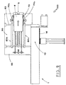
- the reference numeral 100 indicates the proposed machine.
- the machine 100 includes a first conveying line 1 for orderly conveying the articles 2 coming from a related packaging machine, not shown, and brought to a first working station 10, situated in the final area of the first conveying line 1.
- the first working station 10 is aimed at forming groups 20, each of which is composed of a predetermined number of the articles 2, arranged in a row and leaning one against another.
- the first working station 10 includes stop means 11, formed by a bar 12, which is disposed crosswise to the first conveying line 1 and against which the first article 2 of each group 20 being formed stops.
- the position of the bar 12 is adjustable in relation to the size, as will be better explained later.
- the first working station 10 includes also pushing means 14, acting in crosswise direction with respect to the first conveying line 1, so as to push the completed groups 20.
- the pushing means 14 are operated, in a way described later, by a programmable motor means 15 (e.g. a brushless motor), through known, not shown, drive-transmission means.
- a programmable motor means 15 e.g. a brushless motor
- the machine 100 includes a magazine 40 for storing a pile of flat folded tubular blanks 4a ( Figure 2a).
- the magazine 40 is situated over a second conveying line 5, arranged beside the first line 1 and parallel thereto.
- Withdrawing means situated between the magazine 40 and the second conveying line 5, include e.g. a pair of parallel arms 30, hinged together along a common rotation axis 31 and equipped with suction means of known type and not shown ( Figures 2a, 2b).
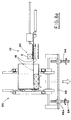
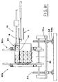
- the arms 30 oscillate, driven by power means 32, between two extreme positions, indicated with broken and continuous line in Figure 2a. In one position the lowermost flat folded tubular blank 4a of the pile in the magazine 40 is withdrawn, while in the other position, the blank just withdrawn and arranged horizontally, is placed in a second working station 50 joined to the second conveying line 5.
- the second working station 50 is transversely aligned with the station 10, in which the groups are formed, and is equipped with blank erecting means 51, which act on the flat folded tubular blank 4a, brought to the second working station 50 by the withdrawing means 3, so as to erect it into a respective container 4 ( Figures 2a and 2b).
- the erecting means 51 include one contrast element 52, moved vertically by a jack 53 between two extreme positions, a lowered position ( Figure 2a) and a raised position ( Figure 2b).
- the contrast element 52 When in the lowered position, the contrast element 52 is situated below the second conveying line 5, so as to push, during raising, the wall 4b of the flat folded blank 4a, which is aligned with the wall leaning against the second conveying line 5.
- a sliding surface 16 is situated in the group forming working station 10, directly below the working arm of the first conveying line 1, and is moved crosswise to the first conveying line by power means 17.
- the sliding surface 16 When in its maximum extracted position, the sliding surface 16 is introduced into the container 4, dwelling in the second working station 50, for a predetermined depth, such that the distance between the end of the surface 16 and the bottom of the container 4 is smaller than the corresponding article 2 dimension.
- the second working station 50 includes also folding means 60, formed by two moving elements 60a, 60b, each of which includes a rectangular frame 61, which features an actuator 66 at each side.
- the frames 61 are arranged vertically, facing each other, symmetrically to a longitudinal middle plane of the second conveying line 5, with respective actuators 66 situated inside the same frames 61.
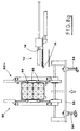
- the actuators 66 act on a plane parallel to the plane in which the related frame lies, according to respective directions converging toward the center of the frame ( Figures 6a, 6b) .
- the dimensions of the frames 61 are such as to define thereinside, when the actuators 66 are in rest position, a free space, which allows a container 4 to pass therethrough.
- the frames 61 are slidably supported by a pair of stems 62 situated below the second conveying line 5, crosswise thereto.
- the frames 61 move close to or away from each other, controlled by a rod 64, which is parallel to the stems 62.
- the rod 64 has two portions threaded in opposite directions, located on opposite sides thereof and engaging with nut screws 65 connected to the frames 61 ( Figures 5a,5b).
- the second conveying line 5, the withdrawing means 3, the erecting means 51 and the folding means 61 are carried by a platform 55, whose height can be changed.
- the means for changing the platform 55 height include e.g. four threaded columns 54, carried by a stationary structure of the machine 100, with possibility to turn about a vertical axis.
- the threaded columns 54 engage with relative nut screws 55 ( Figures 3 and 4).
- Crowns 54a Keyed to the base of the columns 54, are operated synchronously by a chain 58 pulled by a sprocket wheel 59.
- the sprocket wheel 59 is driven by a programmable motor (e.g. brushless motor) in a way described later.
- a programmable motor e.g. brushless motor
- the sprocket wheel 59 is driven by the same motor 15, which drives also the pushing means 14.
- the motor 15 cooperates with a pair of known brake-clutch devices 18, 19 situated between the motor 15 output shaft and respective transmission means, which operate the pushing means 14 and the platform 55.
- the motor 15 can drive alternately the pushing means 14 or the platform 55, which is compatible with the working steps.
- Tape applying means 70 are situated downstream of the second working station 50 for applying adhesive tape to close the bottom and the cover of the container 4 going out of the second working station 50.
- the tape applying means 70 include two tape stretching groups 70a, 70b, advantageously connected with the above mentioned moving elements 60a, 60b of the folding means 60.
- the machine 100 is equipped with all control and detection means, which allow to verify the correct operation thereof in real time and to stop it in case of a jam; for sake of clarity, the above mentioned means have been neither shown nor described, since not strictly relevant to the object of the present invention.
- the rod 64 is rotated by the motor 68, so as to move the moving elements 60a, 60b symmetrically close to each other, from their rest position, in which they are clear of the container 4 ( Figure 5a) to the working position ( Figure 5b), in which the actuators 66 have their reciprocally facing sides aligned with the corresponding folding lines 4c, on which the vertical flaps 4d and horizontal flaps 4f, aimed at forming the bottom and the cover of the container 4, respectively, are hinged on both sides of the central body of the container 4.
- the actuators 66 of the moving element 60a are operated in phase relation, so as to close the container 4 bottom; more precisely, the actuators for closing the vertical flaps 4d are operated first ( Figure 6a) and then the actuators for closing the horizontal flaps 4a are operated, after the first actuators have returned to their rest position ( Figure 6b).
- the actuators 66 acting on the horizontal flaps 4f, remain in their working position until the container 4 leaves the second working station 50.
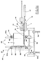
- the pushing means 14 are operated to perform their first stroke, during which they push the side of the just completed first group of articles 20, and, cooperating with the sliding surface 16, transfer it inside the container 4, close to the bottom thereof.
- the pushing means 14 return to their initial position and wait for the next group of articles 20 to be formed.
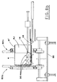
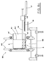
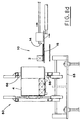
- the programmable motor means 15 must operate the pushing means 14 to perform three strokes, the first of which being the one just described, and the other two having the amplitude decreased each time by the depth of the group 20 ( Figure 8b).
- the programmable motor means 15 connects, by the above mentioned devices brake-friction 18, 19, with the means adjusting the platform 55 level, so as to lower it by an entity corresponding to the articles 2 height.
- the second conveying line 5 is operated, so as to bring the container 4 out of the second working station 50.
- the movement of the container 4 toward the outlet of the second conveying line 5 allows to finish the taping operation, thus completing the machine 100 working cycle.
- the working cycle of the proposed machine has been conceived like a working cycle of an operator who manually fills containers: this allowed to obtain simple movements thus reducing the total number of the machine components and the number of size matching elements.
- the limited working speed of the machine 100 ensures the extreme reliability thereof and minimizes jamming risk and, from the other side, it satisfies normal needs of a production line of articles 2.
- the number of containers 4 to be packaged in a time unit results from the relation between the number of articles 2 produced in the same time unit and the number of the articles 2, which can be housed in the container 4, thus it is evident that the machine capabilities are considerable.
- the machine 100 working way allows to handle not only rigid and regular form articles 2, but also soft and/or delicate, which is not possible with the known machines conceived for less diversified use.
Landscapes
- Engineering & Computer Science (AREA)
- Mechanical Engineering (AREA)
- Making Paper Articles (AREA)
- Containers And Plastic Fillers For Packaging (AREA)
Applications Claiming Priority (2)
| Application Number | Priority Date | Filing Date | Title |
|---|---|---|---|
| IT1999BO000116A IT1309038B1 (it) | 1999-03-11 | 1999-03-11 | Macchina per il confezionamento di fardelli in contenitori ottenuti da fustellati tubolari in configurazione appiattita,e per la chiusura di |
| ITBO990116 | 1999-03-11 |
Publications (1)
| Publication Number | Publication Date |
|---|---|
| EP1035018A1 true EP1035018A1 (de) | 2000-09-13 |
Family
ID=11343813
Family Applications (1)
| Application Number | Title | Priority Date | Filing Date |
|---|---|---|---|
| EP00105059A Withdrawn EP1035018A1 (de) | 1999-03-11 | 2000-03-09 | Maschine zum Verpacken von Gruppen von Gegenständen in aus flach gefalteten schlauchförmigen Zuschnitten erzeugten Behältern, und zum Verschliessen der gefüllten Behälter |
Country Status (2)
| Country | Link |
|---|---|
| EP (1) | EP1035018A1 (de) |
| IT (1) | IT1309038B1 (de) |
Cited By (7)
| Publication number | Priority date | Publication date | Assignee | Title |
|---|---|---|---|---|
| NL1017948C2 (nl) * | 2001-04-26 | 2002-10-29 | Multifoil Bv | Inrichting voor het gecontroleerd in een houder plaatsen van producten alsmede een houder en een transportruimte. |
| EP1407992A1 (de) * | 2002-10-10 | 2004-04-14 | Multifoil B.V. | Vorrichtung zum kontrollierten Einlegen von Erzeugnissen in einen Behälter, sowie ein Behälter und ein Transportfahrzeug |
| EP1980494A1 (de) * | 2007-04-13 | 2008-10-15 | Diseños Integrales del Embalaje, s.a. | Vorrichtung für die Anpassung der Höhe von Faltschachteln und Faltschachtel dafür |
| DE102008010432A1 (de) * | 2008-02-21 | 2009-08-27 | Focke & Co.(Gmbh & Co. Kg) | Verfahren und Vorrichtung zum Einführen von (Schlauch-)Beuteln in Kartons |
| EP2743189A1 (de) * | 2012-12-14 | 2014-06-18 | MediSeal GmbH | Einbringen einer Mehrzahl von Stapeln von Blisterverpackungen in eine Faltschachtel |
| WO2016117182A1 (ja) * | 2015-01-23 | 2016-07-28 | 株式会社イシダ | 箱詰め装置 |
| NL2019235A (en) * | 2016-07-12 | 2018-01-15 | Ishida Seisakusho | Boxing apparatus |
Citations (3)
| Publication number | Priority date | Publication date | Assignee | Title |
|---|---|---|---|---|
| FR2622534A1 (fr) * | 1987-10-30 | 1989-05-05 | Letard Guy | Procede de mise en conteneur couche par couche de produits de detail des conteneurs, et un systeme pour la mise en oeuvre du procede |
| EP0734948A1 (de) * | 1995-03-30 | 1996-10-02 | MARCHESINI GROUP S.p.A. | Vorrichtung zum automatischen Verpacken von Gegenständen in, aus schlauchförmigen Zuschnitten hergestellten, Verpackungen |
| US5732536A (en) * | 1996-10-28 | 1998-03-31 | Industrial Technology Research Institute | Tape roll in-series package machine |
-
1999
- 1999-03-11 IT IT1999BO000116A patent/IT1309038B1/it active
-
2000
- 2000-03-09 EP EP00105059A patent/EP1035018A1/de not_active Withdrawn
Patent Citations (3)
| Publication number | Priority date | Publication date | Assignee | Title |
|---|---|---|---|---|
| FR2622534A1 (fr) * | 1987-10-30 | 1989-05-05 | Letard Guy | Procede de mise en conteneur couche par couche de produits de detail des conteneurs, et un systeme pour la mise en oeuvre du procede |
| EP0734948A1 (de) * | 1995-03-30 | 1996-10-02 | MARCHESINI GROUP S.p.A. | Vorrichtung zum automatischen Verpacken von Gegenständen in, aus schlauchförmigen Zuschnitten hergestellten, Verpackungen |
| US5732536A (en) * | 1996-10-28 | 1998-03-31 | Industrial Technology Research Institute | Tape roll in-series package machine |
Cited By (11)
| Publication number | Priority date | Publication date | Assignee | Title |
|---|---|---|---|---|
| NL1017948C2 (nl) * | 2001-04-26 | 2002-10-29 | Multifoil Bv | Inrichting voor het gecontroleerd in een houder plaatsen van producten alsmede een houder en een transportruimte. |
| EP1407992A1 (de) * | 2002-10-10 | 2004-04-14 | Multifoil B.V. | Vorrichtung zum kontrollierten Einlegen von Erzeugnissen in einen Behälter, sowie ein Behälter und ein Transportfahrzeug |
| EP1980494A1 (de) * | 2007-04-13 | 2008-10-15 | Diseños Integrales del Embalaje, s.a. | Vorrichtung für die Anpassung der Höhe von Faltschachteln und Faltschachtel dafür |
| DE102008010432A1 (de) * | 2008-02-21 | 2009-08-27 | Focke & Co.(Gmbh & Co. Kg) | Verfahren und Vorrichtung zum Einführen von (Schlauch-)Beuteln in Kartons |
| EP2743189A1 (de) * | 2012-12-14 | 2014-06-18 | MediSeal GmbH | Einbringen einer Mehrzahl von Stapeln von Blisterverpackungen in eine Faltschachtel |
| WO2016117182A1 (ja) * | 2015-01-23 | 2016-07-28 | 株式会社イシダ | 箱詰め装置 |
| JP2016135681A (ja) * | 2015-01-23 | 2016-07-28 | 株式会社イシダ | 箱詰め装置 |
| US10549872B2 (en) | 2015-01-23 | 2020-02-04 | Ishida Co., Ltd. | Box packing apparatus |
| NL2019235A (en) * | 2016-07-12 | 2018-01-15 | Ishida Seisakusho | Boxing apparatus |
| AU2017204754B2 (en) * | 2016-07-12 | 2018-03-15 | Ishida Co., Ltd. | Boxing apparatus |
| US10787281B2 (en) | 2016-07-12 | 2020-09-29 | Ishida Co., Ltd. | Boxing apparatus |
Also Published As
| Publication number | Publication date |
|---|---|
| IT1309038B1 (it) | 2002-01-15 |
| ITBO990116A1 (it) | 2000-09-11 |
| ITBO990116A0 (it) | 1999-03-11 |
Similar Documents
| Publication | Publication Date | Title |
|---|---|---|
| US5536231A (en) | Apparatus and method for picking and erecting carton blanks | |
| EP2108505B1 (de) | Vorrichtung zum Aufrichten flach gefalteter rohrförmiger Zuschnitte | |
| US8961380B2 (en) | Method and system for forming a carton from a carton blank | |
| US5106359A (en) | Carton formation system | |
| US5393291A (en) | Mini case erector | |
| US9309017B2 (en) | Item loading apparatus | |
| US7708678B2 (en) | Method for erecting tubular blanks and a station, in which this method is carried out | |
| US11745457B2 (en) | Method and apparatus for forming containers | |
| US12275211B2 (en) | Machine for forming a container from a blank | |
| US6955032B2 (en) | Shuttle packer packaging machine | |
| US20080300123A1 (en) | Article Handling Device | |
| EP1717017B1 (de) | Kartonformeinrichtung mit schwenkbaren Vorrichtungen mit Rollen | |
| CN206704590U (zh) | 一种可适应多规格浅盘型纸盒插舌包装机器人 | |
| EP1437302A1 (de) | Vorrichtung fürs weit Öffnen von den oberen Laschen von rechteckigen Schachteln | |
| WO2007129201A2 (en) | Machine for forming packing boxes, blank and packing box | |
| US4787881A (en) | Arrangement for the raising of packing container blanks | |
| US6306070B1 (en) | Apparatus for erecting and sealing flat containers and associated methods | |
| EP0734952B1 (de) | Vorrichtung zum Entnehmen und Aufrichten von schlauchförmigen Zuschnitten, in Kartoniermaschinen und dergleichen | |
| KR19990063650A (ko) | 고속 용지 조립 장치 및 조립방법 | |
| ITBO990116A1 (it) | Macchina per il confezionamento di fardelli in contenitori ottenuti da fustellati tubolari in configurazione appiattita e per la chiusura di | |
| EP4512725B1 (de) | Verfahren und system zum anordnen von säcken oder beuteln in schachteln | |
| RU2106U1 (ru) | Автоматическая упаковочная линия | |
| US2738715A (en) | Apparatus for forming a carton |
Legal Events
| Date | Code | Title | Description |
|---|---|---|---|
| PUAI | Public reference made under article 153(3) epc to a published international application that has entered the european phase |
Free format text: ORIGINAL CODE: 0009012 |
|
| AK | Designated contracting states |
Kind code of ref document: A1 Designated state(s): AT BE CH CY DE DK ES FI FR GB GR IE IT LI LU MC NL PT SE |
|
| AX | Request for extension of the european patent |
Free format text: AL;LT;LV;MK;RO;SI |
|
| AKX | Designation fees paid | ||
| STAA | Information on the status of an ep patent application or granted ep patent |
Free format text: STATUS: THE APPLICATION HAS BEEN WITHDRAWN |
|
| 18W | Application withdrawn |
Withdrawal date: 20010528 |
|
| REG | Reference to a national code |
Ref country code: DE Ref legal event code: 8566 |