EP1035313A2 - Méthode et dispositif pour augmanter la temperature des gaz d'echappement - Google Patents
Méthode et dispositif pour augmanter la temperature des gaz d'echappement Download PDFInfo
- Publication number
- EP1035313A2 EP1035313A2 EP00102025A EP00102025A EP1035313A2 EP 1035313 A2 EP1035313 A2 EP 1035313A2 EP 00102025 A EP00102025 A EP 00102025A EP 00102025 A EP00102025 A EP 00102025A EP 1035313 A2 EP1035313 A2 EP 1035313A2
- Authority
- EP
- European Patent Office
- Prior art keywords
- exhaust gas
- gas temperature
- temperature
- combustion engine
- internal combustion
- Prior art date
- Legal status (The legal status is an assumption and is not a legal conclusion. Google has not performed a legal analysis and makes no representation as to the accuracy of the status listed.)
- Granted
Links
Images
Classifications
-
- F—MECHANICAL ENGINEERING; LIGHTING; HEATING; WEAPONS; BLASTING
- F01—MACHINES OR ENGINES IN GENERAL; ENGINE PLANTS IN GENERAL; STEAM ENGINES
- F01N—GAS-FLOW SILENCERS OR EXHAUST APPARATUS FOR MACHINES OR ENGINES IN GENERAL; GAS-FLOW SILENCERS OR EXHAUST APPARATUS FOR INTERNAL-COMBUSTION ENGINES
- F01N9/00—Electrical control of exhaust gas treating apparatus
- F01N9/005—Electrical control of exhaust gas treating apparatus using models instead of sensors to determine operating characteristics of exhaust systems, e.g. calculating catalyst temperature instead of measuring it directly
-
- F—MECHANICAL ENGINEERING; LIGHTING; HEATING; WEAPONS; BLASTING
- F02—COMBUSTION ENGINES; HOT-GAS OR COMBUSTION-PRODUCT ENGINE PLANTS
- F02D—CONTROLLING COMBUSTION ENGINES
- F02D41/00—Electrical control of supply of combustible mixture or its constituents
- F02D41/0002—Controlling intake air
-
- F—MECHANICAL ENGINEERING; LIGHTING; HEATING; WEAPONS; BLASTING
- F02—COMBUSTION ENGINES; HOT-GAS OR COMBUSTION-PRODUCT ENGINE PLANTS
- F02D—CONTROLLING COMBUSTION ENGINES
- F02D41/00—Electrical control of supply of combustible mixture or its constituents
- F02D41/02—Circuit arrangements for generating control signals
- F02D41/021—Introducing corrections for particular conditions exterior to the engine
- F02D41/0235—Introducing corrections for particular conditions exterior to the engine in relation with the state of the exhaust gas treating apparatus
- F02D41/024—Introducing corrections for particular conditions exterior to the engine in relation with the state of the exhaust gas treating apparatus to increase temperature of the exhaust gas treating apparatus
- F02D41/0245—Introducing corrections for particular conditions exterior to the engine in relation with the state of the exhaust gas treating apparatus to increase temperature of the exhaust gas treating apparatus by increasing temperature of the exhaust gas leaving the engine
-
- F—MECHANICAL ENGINEERING; LIGHTING; HEATING; WEAPONS; BLASTING
- F02—COMBUSTION ENGINES; HOT-GAS OR COMBUSTION-PRODUCT ENGINE PLANTS
- F02D—CONTROLLING COMBUSTION ENGINES
- F02D41/00—Electrical control of supply of combustible mixture or its constituents
- F02D41/02—Circuit arrangements for generating control signals
- F02D41/14—Introducing closed-loop corrections
- F02D41/1438—Introducing closed-loop corrections using means for determining characteristics of the combustion gases; Sensors therefor
- F02D41/1444—Introducing closed-loop corrections using means for determining characteristics of the combustion gases; Sensors therefor characterised by the characteristics of the combustion gases
- F02D41/1446—Introducing closed-loop corrections using means for determining characteristics of the combustion gases; Sensors therefor characterised by the characteristics of the combustion gases the characteristics being exhaust temperatures
-
- F—MECHANICAL ENGINEERING; LIGHTING; HEATING; WEAPONS; BLASTING
- F02—COMBUSTION ENGINES; HOT-GAS OR COMBUSTION-PRODUCT ENGINE PLANTS
- F02D—CONTROLLING COMBUSTION ENGINES
- F02D41/00—Electrical control of supply of combustible mixture or its constituents
- F02D41/30—Controlling fuel injection
- F02D41/3011—Controlling fuel injection according to or using specific or several modes of combustion
- F02D41/3017—Controlling fuel injection according to or using specific or several modes of combustion characterised by the mode(s) being used
- F02D41/3023—Controlling fuel injection according to or using specific or several modes of combustion characterised by the mode(s) being used a mode being the stratified charge spark-ignited mode
-
- F—MECHANICAL ENGINEERING; LIGHTING; HEATING; WEAPONS; BLASTING
- F02—COMBUSTION ENGINES; HOT-GAS OR COMBUSTION-PRODUCT ENGINE PLANTS
- F02D—CONTROLLING COMBUSTION ENGINES
- F02D41/00—Electrical control of supply of combustible mixture or its constituents
- F02D41/30—Controlling fuel injection
- F02D41/3011—Controlling fuel injection according to or using specific or several modes of combustion
- F02D41/3076—Controlling fuel injection according to or using specific or several modes of combustion with special conditions for selecting a mode of combustion, e.g. for starting, for diagnosing
-
- F—MECHANICAL ENGINEERING; LIGHTING; HEATING; WEAPONS; BLASTING
- F02—COMBUSTION ENGINES; HOT-GAS OR COMBUSTION-PRODUCT ENGINE PLANTS
- F02B—INTERNAL-COMBUSTION PISTON ENGINES; COMBUSTION ENGINES IN GENERAL
- F02B75/00—Other engines
- F02B75/12—Other methods of operation
- F02B2075/125—Direct injection in the combustion chamber for spark ignition engines, i.e. not in pre-combustion chamber
-
- Y—GENERAL TAGGING OF NEW TECHNOLOGICAL DEVELOPMENTS; GENERAL TAGGING OF CROSS-SECTIONAL TECHNOLOGIES SPANNING OVER SEVERAL SECTIONS OF THE IPC; TECHNICAL SUBJECTS COVERED BY FORMER USPC CROSS-REFERENCE ART COLLECTIONS [XRACs] AND DIGESTS
- Y02—TECHNOLOGIES OR APPLICATIONS FOR MITIGATION OR ADAPTATION AGAINST CLIMATE CHANGE
- Y02T—CLIMATE CHANGE MITIGATION TECHNOLOGIES RELATED TO TRANSPORTATION
- Y02T10/00—Road transport of goods or passengers
- Y02T10/10—Internal combustion engine [ICE] based vehicles
- Y02T10/12—Improving ICE efficiencies
-
- Y—GENERAL TAGGING OF NEW TECHNOLOGICAL DEVELOPMENTS; GENERAL TAGGING OF CROSS-SECTIONAL TECHNOLOGIES SPANNING OVER SEVERAL SECTIONS OF THE IPC; TECHNICAL SUBJECTS COVERED BY FORMER USPC CROSS-REFERENCE ART COLLECTIONS [XRACs] AND DIGESTS
- Y02—TECHNOLOGIES OR APPLICATIONS FOR MITIGATION OR ADAPTATION AGAINST CLIMATE CHANGE
- Y02T—CLIMATE CHANGE MITIGATION TECHNOLOGIES RELATED TO TRANSPORTATION
- Y02T10/00—Road transport of goods or passengers
- Y02T10/10—Internal combustion engine [ICE] based vehicles
- Y02T10/40—Engine management systems
Definitions
- the invention relates to a method and a device for increasing the exhaust gas temperature 8. According to the preamble of claim 1 and 8 respectively.
- JP 10054287 A the ignition point to adjust.
- An increase in exhaust gas temperature in an internal combustion engine with stratified operation is by adjusting the ignition timing towards late ignition, however, only to a limited extent possible because there is a larger distance between the injection end and the ignition leads to misfires and unstable combustion.
- the object of the invention is a method and an apparatus of the beginning specified type with which the exhaust gas temperature can be increased as required, while at the same time in short-term idling or in low part-load operation the good efficiency of an unthrottled one Shift operation should be used.
- the exhaust gas temperature is raised by throttling only if the exhaust gas temperature falls below a threshold value is.
- the throttling can preferably be time and / or temperature controlled, so that the strength of the throttling to the respective operating conditions is customizable.
- the catalyst device can be pre-catalysts which are followed, for example, by temperature probes as a device for determining the exhaust gas temperature.
- a storage catalytic converter e.g. NO x storage catalytic converter
- the check can be carried out by evaluating the lambda jump.
- ODB sensors of the engine control can also be used (for example a lambda sensor, a NO x sensor or an exhaust gas temperature sensor).
- the internal combustion engine checks whether the throttling to raise the temperature is sufficient. If this is not the case, then in a second stage switched to homogeneous operation of the internal combustion engine.
- the pre-ignition angle for raising the temperature in the Exhaust system can be reduced.
- the exhaust temperature threshold as a function of vehicle operating or vehicle environment conditions. In particular is an adjustment depending on the ambient temperature and the vehicle speed possible. With this measure, for example when the vehicle is rolling (e.g. when driving downhill), it cools down quickly of the storage catalytic converter through early measures to increase the temperature prevented. The temperature gradient could also be evaluated become. Even with a sharp drop in temperature in the catalyst the motor can be switched directly to homogeneous operation.
- the method according to the invention results and the device for performing such a simple method and inexpensive possibility of a temperature increase according to need, with which both prevents the catalyst from cooling as well the good efficiency of one operating in unthrottled shift operation Engine is maintained.
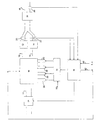
- the drawing shows an internal combustion engine 10 in a schematic manner with an intake duct 11 and two exhaust pipes 16, 18, which in one common exhaust duct 29 open.
- a pre-catalyst 12 and 14 are arranged in the two exhaust lines 16 and 18, a pre-catalyst 12 and 14 are arranged. Behind every pre-catalyst 12, 14, an exhaust gas temperature sensor 20, 22 is provided, which outputs its signal to a control unit 30.
- a NO x storage catalytic converter is arranged in the exhaust gas duct 29, which in turn is followed by a monitor probe 28.
- the monitor probe can check the storage catalytic converter during its regeneration phase and also sends its signal to the control unit 30. The check is carried out by evaluating the lambda jump of the monitor probe 28.
- a throttle device 24 In the inlet channel 11 is a throttle device 24 with an adjustable Throttle valve arranged.
- the throttle device 24 is u. a. of the Control device 30 acted upon.
- the throttle device 24 can also be acted upon by a further control device, but this is not shown here.
- the control device 30 is also provided with an injection control 32 connected, which also from other control units information (Arrow 33) receives.
- Arrow 33 control units information
- Injections become information on injectors 34 through 40 emitted, the corresponding fuel from a (not shown) fuel line bring into the combustion chambers.
- connection 42 between the control device 30 and the Motor 10 provided, about which further information, for example with regard to the valve spread to be selected or the ignition timing adjustment, be given directly to the engine.
- the internal combustion engine is used as a direct injection engine driven in stratified operation.
- the unthrottled Shift operation leads to good efficiency and thus low Fuel consumption.
- vehicle can determine the exhaust gas temperature threshold operating and environmental parameters are taken into account. For example the exhaust gas temperature threshold value depending on the ambient temperature and the driving speed can be selected. So that leaves for example at low ambient temperatures and rolling Prevent the vehicle from cooling down quickly. As a preventive Measure to prevent cooling can be premature Increasing the temperature threshold can be selected. In addition the temperature gradient can be evaluated.
- the signals from the exhaust gas temperature sensors 20 from the control unit 30 and 22 monitors and it is determined whether the throttling in the stratified Operation to a sufficient increase in the exhaust gas temperature leads. If this is not the case, a switchover to a homogeneous takes place Operation of the internal combustion engine with stoichiometric combustion. Accordingly, the injection control 32 as well as the other engine elements operated as intake, exhaust valve control.
- the control device 30 outputs to the engine 10 or its engine controls a corresponding signal or signals from.
- the proposed regulation or the device according to the invention should raise the exhaust gas temperature level by throttling when the exhaust gas temperature threshold falls below the temperature probes downstream of the pre-catalysts. This means that you can continue to use the unthrottled shift operation during a short idle or in the low partial load range, which leads to fuel savings. Throttling takes place only in the case of a longer idling phase or a longer phase of low part-load operation, that is to say when the catalyst temperature falls below 200 ° C., for example. However, this is either time-controlled or is only carried out until the exhaust gas temperature threshold is exceeded again. An additional step is to switch to homogeneous operation with stoichiometric combustion and lambda control if the throttling is not sufficient.
- the two pre-catalysts work as conventional three-way catalysts that convert all pollutant components.
- the effectiveness of the NO x storage catalytic converter used in this case is then not necessary in this operating state. Monitoring of the storage catalytic converter in this operating state could thus be dispensed with.
- the pre-ignition angle can finally be reduced if necessary in a third step.
Landscapes
- Engineering & Computer Science (AREA)
- Chemical & Material Sciences (AREA)
- Combustion & Propulsion (AREA)
- Mechanical Engineering (AREA)
- General Engineering & Computer Science (AREA)
- Analytical Chemistry (AREA)
- Chemical Kinetics & Catalysis (AREA)
- Exhaust Gas After Treatment (AREA)
- Electrical Control Of Air Or Fuel Supplied To Internal-Combustion Engine (AREA)
- Electrical Control Of Ignition Timing (AREA)
- Control Of Throttle Valves Provided In The Intake System Or In The Exhaust System (AREA)
- Combined Controls Of Internal Combustion Engines (AREA)
Applications Claiming Priority (2)
| Application Number | Priority Date | Filing Date | Title |
|---|---|---|---|
| DE19909796A DE19909796A1 (de) | 1999-03-05 | 1999-03-05 | Verfahren und Vorrichtung zur Abgastemperaturerhöhung |
| DE19909796 | 1999-03-05 |
Publications (3)
| Publication Number | Publication Date |
|---|---|
| EP1035313A2 true EP1035313A2 (fr) | 2000-09-13 |
| EP1035313A3 EP1035313A3 (fr) | 2002-05-02 |
| EP1035313B1 EP1035313B1 (fr) | 2003-10-29 |
Family
ID=7899877
Family Applications (1)
| Application Number | Title | Priority Date | Filing Date |
|---|---|---|---|
| EP00102025A Expired - Lifetime EP1035313B1 (fr) | 1999-03-05 | 2000-02-02 | Méthode et dispositif pour augmanter la temperature des gaz d'echappement |
Country Status (5)
| Country | Link |
|---|---|
| US (1) | US6311666B1 (fr) |
| EP (1) | EP1035313B1 (fr) |
| JP (1) | JP2000257450A (fr) |
| DE (2) | DE19909796A1 (fr) |
| ES (1) | ES2208160T3 (fr) |
Cited By (3)
| Publication number | Priority date | Publication date | Assignee | Title |
|---|---|---|---|---|
| EP1296050A1 (fr) * | 2001-09-25 | 2003-03-26 | Ford Global Technologies, Inc., A subsidiary of Ford Motor Company | Système et procédé de régénération d'un dispositif de traitement de gaz d'échappement |
| EP1298301A1 (fr) * | 2001-09-26 | 2003-04-02 | Ford Global Technologies, Inc., A subsidiary of Ford Motor Company | Méthode pour contrôler le démarrage d'un moteur à combustion interne |
| EP1375878A3 (fr) * | 2002-06-27 | 2004-10-13 | DaimlerChrysler AG | Procédé de commande d'un moteur à combustion intèrne à injection directe |
Families Citing this family (6)
| Publication number | Priority date | Publication date | Assignee | Title |
|---|---|---|---|---|
| DE10154664A1 (de) * | 2001-11-07 | 2003-05-22 | Bosch Gmbh Robert | Verfahren, Computerprogramm, Steuer und/oder Regelgerät zum Betreiben einer Brennkraftmaschine sowie Brennkraftmaschine |
| DE102014204509A1 (de) * | 2014-03-12 | 2015-09-17 | Bayerische Motoren Werke Aktiengesellschaft | Wassereinspritzanlage für einen Verbrennungsmotor |
| MX2020006245A (es) * | 2017-12-15 | 2020-09-03 | Nissan Motor | Metodo de control de calentamiento de catalizador para vehiculo hibrido y aparato de control de calentamiento de catalizador para vehiculo hibrido. |
| MX2020006127A (es) * | 2017-12-15 | 2020-08-24 | Nissan Motor | Metodo de control de calentamiento del catalizador para vehiculo hibrido y dispositivo de control de calentamiento del catalizador para vehiculo hibrido. |
| CN112983661B (zh) * | 2021-01-29 | 2022-12-16 | 广西玉柴机器股份有限公司 | 一种发动机高原高寒的热管理控制装置及方法 |
| CN113047970B (zh) * | 2021-03-04 | 2022-11-18 | 广西玉柴机器股份有限公司 | 一种高寒高原快速提高排气温度的方法及装置 |
Citations (1)
| Publication number | Priority date | Publication date | Assignee | Title |
|---|---|---|---|---|
| JPH1054287A (ja) | 1996-08-13 | 1998-02-24 | Toyota Motor Corp | 筒内直接噴射式内燃機関の燃料噴射制御装置 |
Family Cites Families (11)
| Publication number | Priority date | Publication date | Assignee | Title |
|---|---|---|---|---|
| JPS61112715A (ja) * | 1984-11-08 | 1986-05-30 | Toyota Motor Corp | デイ−ゼル機関の排気浄化装置 |
| JP2663720B2 (ja) * | 1990-12-26 | 1997-10-15 | トヨタ自動車株式会社 | ディーゼルエンジンの排気浄化装置 |
| GB2301459B (en) * | 1994-09-29 | 1997-07-02 | Fuji Heavy Ind Ltd | Method for controlling a direct fuel injection engine |
| DE19536098C2 (de) * | 1994-09-29 | 1997-09-18 | Fuji Heavy Ind Ltd | System und Verfahren zur Steuerung der Katalysatoraktivierung in einem Motor mit Kraftstoffdirekteinspritzung |
| JP3052856B2 (ja) * | 1996-10-24 | 2000-06-19 | 三菱自動車工業株式会社 | 排気昇温装置 |
| JP3257423B2 (ja) * | 1996-12-12 | 2002-02-18 | 三菱自動車工業株式会社 | 排気昇温装置 |
| JPH10299463A (ja) * | 1997-04-30 | 1998-11-10 | Toyota Motor Corp | 内燃機関の排気浄化装置 |
| DE19731623B4 (de) * | 1997-07-23 | 2006-11-23 | Volkswagen Ag | Verfahren und Vorrichtung zur De-Sulfatierung von NOx-Speichern bei Dieselmotoren |
| JP3536606B2 (ja) * | 1997-08-21 | 2004-06-14 | 日産自動車株式会社 | 直噴火花点火式内燃機関の燃料噴射制御装置 |
| JP2000227037A (ja) * | 1999-02-05 | 2000-08-15 | Mitsubishi Electric Corp | 筒内噴射式内燃機関の制御装置 |
| US6189316B1 (en) * | 1999-05-19 | 2001-02-20 | Ford Global Technologies, Inc. | Emission device temperature control system |
-
1999
- 1999-03-05 DE DE19909796A patent/DE19909796A1/de not_active Withdrawn
-
2000
- 2000-02-02 EP EP00102025A patent/EP1035313B1/fr not_active Expired - Lifetime
- 2000-02-02 ES ES00102025T patent/ES2208160T3/es not_active Expired - Lifetime
- 2000-02-02 DE DE50004214T patent/DE50004214D1/de not_active Expired - Lifetime
- 2000-02-04 JP JP2000028040A patent/JP2000257450A/ja active Pending
- 2000-03-06 US US09/519,901 patent/US6311666B1/en not_active Expired - Lifetime
Patent Citations (1)
| Publication number | Priority date | Publication date | Assignee | Title |
|---|---|---|---|---|
| JPH1054287A (ja) | 1996-08-13 | 1998-02-24 | Toyota Motor Corp | 筒内直接噴射式内燃機関の燃料噴射制御装置 |
Cited By (5)
| Publication number | Priority date | Publication date | Assignee | Title |
|---|---|---|---|---|
| EP1296050A1 (fr) * | 2001-09-25 | 2003-03-26 | Ford Global Technologies, Inc., A subsidiary of Ford Motor Company | Système et procédé de régénération d'un dispositif de traitement de gaz d'échappement |
| US6644020B2 (en) | 2001-09-25 | 2003-11-11 | Ford Global Technologies, Llc | Device and method for regenerating an exhaust gas aftertreatment device |
| EP1298301A1 (fr) * | 2001-09-26 | 2003-04-02 | Ford Global Technologies, Inc., A subsidiary of Ford Motor Company | Méthode pour contrôler le démarrage d'un moteur à combustion interne |
| US6829888B2 (en) | 2001-09-26 | 2004-12-14 | Ford Global Technologies, Llc | Method for controlling the starting of an internal combustion engine |
| EP1375878A3 (fr) * | 2002-06-27 | 2004-10-13 | DaimlerChrysler AG | Procédé de commande d'un moteur à combustion intèrne à injection directe |
Also Published As
| Publication number | Publication date |
|---|---|
| EP1035313A3 (fr) | 2002-05-02 |
| DE19909796A1 (de) | 2000-09-07 |
| ES2208160T3 (es) | 2004-06-16 |
| EP1035313B1 (fr) | 2003-10-29 |
| US6311666B1 (en) | 2001-11-06 |
| DE50004214D1 (de) | 2003-12-04 |
| JP2000257450A (ja) | 2000-09-19 |
Similar Documents
| Publication | Publication Date | Title |
|---|---|---|
| EP1336037B1 (fr) | Procede et dispositif pour reguler un systeme de traitement subsequent de gaz d'echappement | |
| DE10022981B4 (de) | Schadstoffbegrenzungssystem | |
| EP1117917B1 (fr) | PROCEDE PERMETTANT DE REGENERER UN CATALYSEUR A ACCUMULATION DE NOx | |
| WO2000023694A2 (fr) | Procede de reduction des oxydes d'azote dans les gaz d'echappement d'un moteur a combustion interne fonctionnant avec un melange pauvre | |
| WO2000053902A1 (fr) | Procede de desulfatage d'un catalyseur accumulateur de nox | |
| EP1121519A1 (fr) | PROCEDE ET DISPOSITIF DE DESULFURATION D'UN CATALYSEUR A ACCUMULATION DE NO x? | |
| EP1192340A1 (fr) | Procede pour la verification d'un pot d'echappement catalytique a trois voies d'un moteur a combustion interne | |
| EP1582709B1 (fr) | Méthode de régénération d'un filtre à particule ainsi qu'un système d'échappement avec un filtre à particule | |
| EP1118756A2 (fr) | Méthode et dispositif pour la commande de la régénération d'un catalyseur de stockage de NOx | |
| EP1329627B1 (fr) | Procédé et dispositif de contrôle d'une fonction de protection de composants | |
| DE10008564A1 (de) | Verfahren und Vorrichtung zur Steuerung der Regeneration eines NOx-Speicherkatalysators | |
| EP1035313B1 (fr) | Méthode et dispositif pour augmanter la temperature des gaz d'echappement | |
| DE19536798C2 (de) | Vorrichtung zum Erfassen der Verringerung der Reinigungskapazität eines Katalysators zum Reinigen von Abgas eines Verbrennungsmotors | |
| DE102005013278B4 (de) | Verfahren und Vorrichtung für eine optimierte Kraftstoffsteuerung auf der Grundlage eines Auslass-Sauerstoffsignals zur Reduktion von Fahrzeugemissionen | |
| WO2005066468A2 (fr) | Procede de regeneration d'un catalyseur a accumulation d'oxyde d'azote | |
| EP1111208B1 (fr) | Procédé de réglage d'un mode de fonctionnement d'un moteur à combustion interne pendant la régénération d'un catalyseur à stockage placé dans un tuyau d'échappement | |
| DE10226873B4 (de) | Verfahren zur Steuerung der Betriebsartenwahl einer Verbrennungskraftmaschine | |
| DE60011762T2 (de) | Verfahren und vorrichtung zur begrenzung der regelbaren parameter eines motors | |
| DE102009029586A1 (de) | Verfahren und Steuervorrichtung zum Betreiben einer Brennkraftmaschine | |
| DE10010005B4 (de) | Brennkraftmaschine und Verfahren zur Steuerung einer Brennkraftmaschine | |
| EP1966468B1 (fr) | Procede et dispositif de regeneration d'un systeme de traitement de gaz d'echappement | |
| DE10015330A1 (de) | Verfahren und Vorrichtung zur Abgasreinigung | |
| DE10234849A1 (de) | Verfahren, Computerprogramm und Steuer- und/oder Regelgerät zum Betreiben einer Brennkraftmaschine, sowie Brennkraftmaschine | |
| DE10139848A1 (de) | Kraftfahrzeug mit Abgasreinigungssystem und geregelter Luftzufuhr | |
| DE3485781T2 (de) | Elektronisches steuersystem fuer brennkraftmaschinen mit der faehigkeit, das abwuergen des motors zu verhindern und verfahren dazu. |
Legal Events
| Date | Code | Title | Description |
|---|---|---|---|
| PUAI | Public reference made under article 153(3) epc to a published international application that has entered the european phase |
Free format text: ORIGINAL CODE: 0009012 |
|
| AK | Designated contracting states |
Kind code of ref document: A2 Designated state(s): DE ES FR GB IT SE Kind code of ref document: A2 Designated state(s): AT BE CH CY DE DK ES FI FR GB GR IE IT LI LU MC NL PT SE |
|
| AX | Request for extension of the european patent |
Free format text: AL;LT;LV;MK;RO;SI |
|
| PUAL | Search report despatched |
Free format text: ORIGINAL CODE: 0009013 |
|
| AK | Designated contracting states |
Kind code of ref document: A3 Designated state(s): AT BE CH CY DE DK ES FI FR GB GR IE IT LI LU MC NL PT SE |
|
| AX | Request for extension of the european patent |
Free format text: AL;LT;LV;MK;RO;SI |
|
| RIC1 | Information provided on ipc code assigned before grant |
Free format text: 7F 02D 41/14 A, 7F 02D 33/02 B, 7F 02D 41/02 B |
|
| 17P | Request for examination filed |
Effective date: 20020528 |
|
| AKX | Designation fees paid |
Free format text: DE ES FR GB IT SE |
|
| 17Q | First examination report despatched |
Effective date: 20030115 |
|
| GRAH | Despatch of communication of intention to grant a patent |
Free format text: ORIGINAL CODE: EPIDOS IGRA |
|
| GRAS | Grant fee paid |
Free format text: ORIGINAL CODE: EPIDOSNIGR3 |
|
| GRAA | (expected) grant |
Free format text: ORIGINAL CODE: 0009210 |
|
| AK | Designated contracting states |
Kind code of ref document: B1 Designated state(s): DE ES FR GB IT SE |
|
| REG | Reference to a national code |
Ref country code: GB Ref legal event code: FG4D Free format text: NOT ENGLISH |
|
| GBT | Gb: translation of ep patent filed (gb section 77(6)(a)/1977) |
Effective date: 20031029 |
|
| REG | Reference to a national code |
Ref country code: IE Ref legal event code: FG4D Free format text: GERMAN |
|
| REF | Corresponds to: |
Ref document number: 50004214 Country of ref document: DE Date of ref document: 20031204 Kind code of ref document: P |
|
| REG | Reference to a national code |
Ref country code: SE Ref legal event code: TRGR |
|
| REG | Reference to a national code |
Ref country code: ES Ref legal event code: FG2A Ref document number: 2208160 Country of ref document: ES Kind code of ref document: T3 |
|
| REG | Reference to a national code |
Ref country code: IE Ref legal event code: FD4D |
|
| ET | Fr: translation filed | ||
| PLBE | No opposition filed within time limit |
Free format text: ORIGINAL CODE: 0009261 |
|
| STAA | Information on the status of an ep patent application or granted ep patent |
Free format text: STATUS: NO OPPOSITION FILED WITHIN TIME LIMIT |
|
| 26N | No opposition filed |
Effective date: 20040730 |
|
| PGFP | Annual fee paid to national office [announced via postgrant information from national office to epo] |
Ref country code: ES Payment date: 20080131 Year of fee payment: 9 |
|
| PGFP | Annual fee paid to national office [announced via postgrant information from national office to epo] |
Ref country code: GB Payment date: 20080228 Year of fee payment: 9 Ref country code: IT Payment date: 20080228 Year of fee payment: 9 Ref country code: SE Payment date: 20080219 Year of fee payment: 9 |
|
| PGFP | Annual fee paid to national office [announced via postgrant information from national office to epo] |
Ref country code: FR Payment date: 20080228 Year of fee payment: 9 |
|
| EUG | Se: european patent has lapsed | ||
| GBPC | Gb: european patent ceased through non-payment of renewal fee |
Effective date: 20090202 |
|
| REG | Reference to a national code |
Ref country code: FR Ref legal event code: ST Effective date: 20091030 |
|
| REG | Reference to a national code |
Ref country code: ES Ref legal event code: FD2A Effective date: 20090203 |
|
| PG25 | Lapsed in a contracting state [announced via postgrant information from national office to epo] |
Ref country code: GB Free format text: LAPSE BECAUSE OF NON-PAYMENT OF DUE FEES Effective date: 20090202 Ref country code: FR Free format text: LAPSE BECAUSE OF NON-PAYMENT OF DUE FEES Effective date: 20090302 |
|
| PG25 | Lapsed in a contracting state [announced via postgrant information from national office to epo] |
Ref country code: ES Free format text: LAPSE BECAUSE OF NON-PAYMENT OF DUE FEES Effective date: 20090203 |
|
| PG25 | Lapsed in a contracting state [announced via postgrant information from national office to epo] |
Ref country code: IT Free format text: LAPSE BECAUSE OF NON-PAYMENT OF DUE FEES Effective date: 20090202 |
|
| PG25 | Lapsed in a contracting state [announced via postgrant information from national office to epo] |
Ref country code: SE Free format text: LAPSE BECAUSE OF NON-PAYMENT OF DUE FEES Effective date: 20090203 |
|
| PGFP | Annual fee paid to national office [announced via postgrant information from national office to epo] |
Ref country code: DE Payment date: 20130315 Year of fee payment: 14 |
|
| REG | Reference to a national code |
Ref country code: DE Ref legal event code: R119 Ref document number: 50004214 Country of ref document: DE |
|
| REG | Reference to a national code |
Ref country code: DE Ref legal event code: R119 Ref document number: 50004214 Country of ref document: DE Effective date: 20140902 |
|
| PG25 | Lapsed in a contracting state [announced via postgrant information from national office to epo] |
Ref country code: DE Free format text: LAPSE BECAUSE OF NON-PAYMENT OF DUE FEES Effective date: 20140902 |