EP1035629A2 - Agencement d'aimants permanent pour moteur - Google Patents
Agencement d'aimants permanent pour moteur Download PDFInfo
- Publication number
- EP1035629A2 EP1035629A2 EP00104825A EP00104825A EP1035629A2 EP 1035629 A2 EP1035629 A2 EP 1035629A2 EP 00104825 A EP00104825 A EP 00104825A EP 00104825 A EP00104825 A EP 00104825A EP 1035629 A2 EP1035629 A2 EP 1035629A2
- Authority
- EP
- European Patent Office
- Prior art keywords
- pole
- poles
- auxiliary
- motor
- magnet
- Prior art date
- Legal status (The legal status is an assumption and is not a legal conclusion. Google has not performed a legal analysis and makes no representation as to the accuracy of the status listed.)
- Granted
Links
Images


Classifications
-
- H—ELECTRICITY
- H02—GENERATION; CONVERSION OR DISTRIBUTION OF ELECTRIC POWER
- H02K—DYNAMO-ELECTRIC MACHINES
- H02K1/00—Details of the magnetic circuit
- H02K1/06—Details of the magnetic circuit characterised by the shape, form or construction
- H02K1/12—Stationary parts of the magnetic circuit
- H02K1/17—Stator cores with permanent magnets
Definitions
- the present invention relates to a motor having a plurality of permanent-magnet main poles and a plurality of auxiliary poles which are alternately fixed to an inner periphery of a motor yoke.
- a DC motor disclosed in U.S. Patent 5,723, 929 or its corresponding Japanese application JP-A 9-84315 has a plurality of annularly aligned permanent-magnet main poles and a plurality of auxiliary poles disposed between adjacent two of the main poles.
- the auxiliary poles are supported by a cylindrical sleeve which is fitted to the inner periphery of the main poles.
- the sleeve increases the distance or air gap between an armature and the main poles and reduces the output power of the motor.
- a sleeve is bulged by press-forming against the main and auxiliary poles to make the inside diameter thereof uniform. This may damage permanent-magnets of the main poles and the auxiliary poles.
- the present invention has been made in view of the above-stated circumstances.
- a main object of the invention is to provide a pole arrangement which makes the air gap as small as possible.
- Another object of the invention is to provide a pole arrangement in which permanent magnets are immune to damage caused by outside pressure.
- a pole arrangement of a motor includes a plurality of permanent-magnet main poles disposed circumferentially at equal intervals on the inner periphery of a yoke, a plurality of magnet holders with auxiliary poles therein disposed between the adjacent main poles.
- Each magnet holder preferably includes resilient stopper means pressing the main poles in the circumferential direction, and each auxiliary pole is disposed inside the resilient stopper means.
- the auxiliary poles can be supported by the magnet holders, and additional sleeve is not necessary. As a result, the air gap can be made as small as possible.
- each of the magnet holders can be held between two of the main poles by the counteraction thereof. This eliminates additional fixing means such as welding or rivetting.
- Each main pole can be held only by the resilient stopper means from circumferentially outside. Therefore, it is not necessary to fix the magnet holders to the inner periphery of the yoke by an adhesive or the like, and the main poles can be assembled easily at a low cost.
- each magnet holder may further include a first stopper member supporting axially opposite ends of the auxiliary pole, a second stopper member supporting axially opposite ends of the main poles, and a third stopper member supporting an outer periphery of the auxiliary poles.
- the magnet holder can be formed into a simple U-pipe.
- the yoke has a pair of projections on an inner periphery thereof, and each magnet holder has a pair of cavities at axially opposite ends which are engaged by the projections so that the magnet holders can be fixed to the yoke in both axial and circumferential directions.
- a motor having a pole arrangement according to a first embodiment of the invention is described with reference to Figs. 1 - 4.
- DC motor 1 has a pole arrangement including a plurality of permanent-magnet main poles 2, a yoke 3, a plurality of auxiliary poles 4 and armature 5 rotatably held within main poles 2 and auxiliary poles 4.
- Main poles 2 are circumferentially aligned and fixed to the inner periphery of yoke 3 at equal intervals.
- the permanent magnets of main poles 2 are magnetized to form S-pole and N-pole in the radial direction so that one of main poles 2 is different in magnetic pole from the adjacent poles, as shown in Fig. 1.
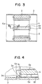
- Yoke 3 is a cylindrical iron member having projections 3a on the inner periphery thereof, as shown in Fig. 4. Projections 3a can be formed by punching or the like to have a gentle slope 3b which descends in the axial direction.
- Each auxiliary pole 4 is disposed adjacent two of main poles 2.
- Auxiliary poles 4 are also comprised of permanent magnets.
- the auxiliary-pole permanent magnets are magnetized to alternately form S-pole and N-pole in the circumferential direction, so that the magnetic pole of the inner periphery thereof can be the same as the magnetic pole of the inner periphery of those of main poles 2 adjacent thereto.
- each magnet holder 6 is comprised of a stainless-plate-U-pipe portion having base plate 61 and side plates 62. Each magnet holder is disposed between adjacent main poles 2, and each auxiliary pole 4 is disposed inside the U-pipe portion.
- the circumferential width of the base plate 61 of magnet holders 6 is approximately equal to the distance between adjacent two of main poles 2, and side plates 62 extends to be slightly open. Accordingly, two side plates 62 of magnet holders 6 resiliently press the circumferential sides of main poles 2, and magnet holders 6 are held between main poles 2 by counteraction.
- Each magnet holder 6 has a pair of inwardly extending L-bends 6a at the edge of side plates 62, which hold auxiliary poles 4 at the inner surface thereof.
- Each magnet holder 6 also has rectangular cavities 6b formed at the axially opposite ends thereof and a pair of first stoppers 6c extending from cavities 6b, two pairs of second stoppers 6d extending from axially opposite ends of side plates 62, and two pairs of third stoppers 6e extending from a pair of cut-outs formed at base plate 61.
- auxiliary poles 4 are axially inserted into the U-pipe portion of magnet holders 6 so that the pair of L-bends 6a holds auxiliary poles 4. Consequently, the two pairs of third stoppers 6e resiliently press the radially outer periphery of auxiliary poles 4.
- Each first stopper 6c is bent radially inward at the axially opposite ends of magnet holder 6 to support auxiliary poles 4, as shown in Fig. 4. Thus, axial and radial shifts of auxiliary poles 4 are restricted.
- each magnet holder 6 is inserted into the space between adjacent main poles 2 with base plate 61 being opposite to yoke 3. Since side plates 62 have been formed to slightly open, they are slightly compressed between adjacent main poles 2 after they are inserted. Thus, main poles 2 are held between magnet holders 6 under the spring force thereof. Because side plates 62 resiliently press the side walls of main poles 2, magnet holder 6 is held between main poles 2 by the counteraction thereof.
- Projections 3a are fitted into cavities 6b at the axially opposite ends thereof so that the axial and circumferential positions thereof relative to yoke 3 are fixed as shown in Fig. 3. Since slope 3b descends in the axial direction, cavities 6b are not obstructed by projections 3a when magnet holders 6 are inserted between main poles 2. Then, second stoppers 6d expands to hold the axially opposite ends of main poles 2.
- any sleeve or the like is not necessary to fix auxiliary poles 4.
- the air gap can be made as small as possible, resulting in increase in the output power.
- the permanent magnets become immune from outside stresses.
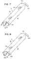
- a pole arrangement according to a second embodiment of the invention is described with reference to Fig. 5.
- first stopper 6c of the magnet holder according to the first embodiment is omitted.
- Each of second stoppers 6d1 and 6d2 has an axial length to provide stronger holding force as compared with first stoppers 6c of the first embodiment, because second stoppers 6d1 and 6d2 have a sufficient strength corresponding to the axial length thereof while first stoppers 6c are bent in the thickness direction
- a pole arrangement according to a third embodiment of the invention has iron pieces 7, as commutating poles, between main poles 2, as shown in Figs. 6 and 7.
- Each magnet holder 6 has a pair of cavities 6b at the axially opposite ends thereof, a pair of first stoppers 6c extending from cavities 6b, two pairs of second stoppers 6d extending outward from side plates 62, and a pair of third stoppers 6e extending from base plate 61 into the inside of the U-pipe portion of magnet holder 6.
- Each iron piece 7 is inserted between third stoppers 6e and one of side plates 62 as shown in Fig. 6, so that it is supported by L-bend 6a at the radially inner periphery thereof, between third stoppers 6e and one of side plates 62, and by a pair of first stoppers 6c at axially opposite surfaces thereof.
- iron pieces 7 are fixed and held inside magnet holders 6.
- Each magnet holder 6 is inserted between circumferentially adjoining two main poles 2 so that a pair of cavities 6b engages a pair of projections 3a of yoke 3 to fix magnet holders 6 to yoke 3 in the axial and circumferential directions.
- Magnet holders 6 and main poles 2 are the same as the first embodiment.
- Each magnet holder 6 resiliently presses the side surfaces of the adjacent main poles 2 via side plates 62 and is also held between adjacent main poles 2 in return.
- a pole arrangement according to a fourth embodiment of the invention is described with reference to Fig. 8.
- One pair of second stoppers 6d1 is bent outwardly, while the other pair of second stoppers 6d2 is bent inwardly.
- the axially end surfaces of main poles 2 can be supported by second stoppers 6d1, and the axially end surfaces of iron pieces 7 are supported by second stopper 6d2.
- first stoppers 6c of the third embodiment is omitted, and second stopper 6d2 are made stronger than first stoppers 6c of the third embodiment.
- a pole arrangement according to a fifth embodiment of the invention is described with reference to Fig. 9A and Fig. 9B.
- a pair of side plates 62 has inwardly extending L-bends 6a.
- Each L-bend 6a has a pair of resilient arms 6f at the longitudinally opposite ends.
- Each resilient arms 6f is cut from magnet holder 6 and inclines toward base plate 61 to exert spring force on the inner periphery of auxiliary pole 4 disposed in the U-pipe portion of magnet holder 6.
- each auxiliary pole 4 is retained between the pair of resilient arms 6f and third stoppers 6e of base plate 61.
- Claw 6g is formed at the edge of each resilient arm 6f so that a pair of claws 6g at the opposite ends supports axially opposite ends of auxiliary pole 4 to restrict axial movement of each main pole 2 relative to each magnet holder 6.
Landscapes
- Engineering & Computer Science (AREA)
- Power Engineering (AREA)
- Permanent Field Magnets Of Synchronous Machinery (AREA)
- Dc Machiner (AREA)
Applications Claiming Priority (2)
| Application Number | Priority Date | Filing Date | Title |
|---|---|---|---|
| JP6592599 | 1999-03-12 | ||
| JP06592599A JP3417332B2 (ja) | 1999-03-12 | 1999-03-12 | 直流モータ |
Publications (3)
| Publication Number | Publication Date |
|---|---|
| EP1035629A2 true EP1035629A2 (fr) | 2000-09-13 |
| EP1035629A3 EP1035629A3 (fr) | 2001-02-14 |
| EP1035629B1 EP1035629B1 (fr) | 2006-07-26 |
Family
ID=13301045
Family Applications (1)
| Application Number | Title | Priority Date | Filing Date |
|---|---|---|---|
| EP00104825A Expired - Lifetime EP1035629B1 (fr) | 1999-03-12 | 2000-03-06 | Agencement d'aimants permanent pour moteur |
Country Status (4)
| Country | Link |
|---|---|
| US (1) | US6376956B1 (fr) |
| EP (1) | EP1035629B1 (fr) |
| JP (1) | JP3417332B2 (fr) |
| DE (1) | DE60029504T2 (fr) |
Cited By (11)
| Publication number | Priority date | Publication date | Assignee | Title |
|---|---|---|---|---|
| US6465925B2 (en) | 2000-10-26 | 2002-10-15 | Denso Corporation | Rotary electric machine having auxiliary poles |
| EP1211778A3 (fr) * | 2000-11-30 | 2004-01-21 | Valeo Mando Electrical Systems Korea Limited | Support d'aimant pour démarreur |
| WO2007051668A1 (fr) * | 2005-11-07 | 2007-05-10 | Siemens Aktiengesellschaft | Moteur électrique avec des éléments magnétiques arqués fixés à la périphérie interne du boîtier du moteur |
| FR2910194A1 (fr) * | 2006-12-15 | 2008-06-20 | Valeo Equip Electr Moteur | Machine electrique tournante, notamment pour demarreur de vehicule automobile |
| FR2910192A1 (fr) * | 2006-12-15 | 2008-06-20 | Valeo Equip Electr Moteur | Machine electrique tournante, en particulier pour un demarreur de vehicule automobile |
| WO2008074954A1 (fr) * | 2006-12-15 | 2008-06-26 | Valeo Equipements Electriques Moteur | Machine electrique tournante, en particulier pour un demarreur de vehicule automobile |
| CN1913289B (zh) * | 2005-08-10 | 2011-03-30 | 三菱电机株式会社 | 旋转电机的转子及其组装方法 |
| CN105811605A (zh) * | 2016-05-13 | 2016-07-27 | 东莞国亮电机有限公司 | 定位弹片及定子磁钢固定结构 |
| CN107846119A (zh) * | 2017-08-11 | 2018-03-27 | 马鞍山和腾汽车配件有限公司 | 一种胀紧式起动机定子总成的装配方法 |
| CN109650500A (zh) * | 2019-01-22 | 2019-04-19 | 中国科学院上海高等研究院 | 一种用于磁混凝水处理的高梯度磁分离器的磁场排布结构 |
| DE102018009455A1 (de) | 2017-12-11 | 2019-06-13 | Valeo Equipements Electriques Moteur | Elektromotor für einen Anlasser eines Verbrennungsmotors und Anlasser, der mit einem solchen Elektromotor ausgestattet ist |
Families Citing this family (35)
| Publication number | Priority date | Publication date | Assignee | Title |
|---|---|---|---|---|
| JP3507395B2 (ja) * | 2000-03-03 | 2004-03-15 | 株式会社日立製作所 | 回転電機及びそれを用いた電動車両 |
| ITBZ20010043A1 (it) * | 2001-09-13 | 2003-03-13 | High Technology Invest Bv | Generatore elettrico azionato da energia eolica. |
| US6548932B1 (en) * | 2001-10-31 | 2003-04-15 | Electric Boat Corporation | Nonmagnetic magnet retention channel arrangement for high speed rotors |
| US6492754B1 (en) * | 2001-10-31 | 2002-12-10 | Electric Boat Corporation | Magnet retention channel arrangement for high speed operation |
| GB2393583B (en) * | 2002-09-27 | 2006-03-22 | Automotive Motion Tech Ltd | Electric motor |
| JP4301040B2 (ja) * | 2004-03-10 | 2009-07-22 | 日立工機株式会社 | 電動工具 |
| ITBZ20050063A1 (it) * | 2005-11-29 | 2007-05-30 | High Technology Invest Bv | Pacco di lamierini per generatori e motori elettrici e procedimento per la sua attuazione |
| WO2007034305A1 (fr) * | 2005-09-21 | 2007-03-29 | High Techonology Investments, B.V. | Systeme d'etancheite de roulement a joint a vis et a garniture a labyrinthes combines |
| ITBZ20050062A1 (it) * | 2005-11-29 | 2007-05-30 | High Technology Invest Bv | Rotore a magneti permanenti per generatori e motori elettrici |
| JP2008048492A (ja) * | 2006-08-11 | 2008-02-28 | Denso Corp | 回転電機 |
| JP5076521B2 (ja) * | 2007-01-31 | 2012-11-21 | 株式会社デンソー | スタータ用モータ |
| US8138649B2 (en) * | 2007-08-02 | 2012-03-20 | Remy Technologies, L.L.C. | Magnet support and retention system for hybrid rotors |
| ITMI20081122A1 (it) | 2008-06-19 | 2009-12-20 | Rolic Invest Sarl | Generatore eolico provvisto di un impianto di raffreddamento |
| IT1390758B1 (it) | 2008-07-23 | 2011-09-23 | Rolic Invest Sarl | Generatore eolico |
| JP5146184B2 (ja) * | 2008-08-01 | 2013-02-20 | 株式会社デンソー | 磁石界磁型モータの製造方法 |
| IT1391939B1 (it) | 2008-11-12 | 2012-02-02 | Rolic Invest Sarl | Generatore eolico |
| IT1391770B1 (it) | 2008-11-13 | 2012-01-27 | Rolic Invest Sarl | Generatore eolico per la generazione di energia elettrica |
| IT1392804B1 (it) | 2009-01-30 | 2012-03-23 | Rolic Invest Sarl | Imballo e metodo di imballo per pale di generatori eolici |
| IT1393937B1 (it) * | 2009-04-09 | 2012-05-17 | Rolic Invest Sarl | Aerogeneratore |
| IT1393707B1 (it) | 2009-04-29 | 2012-05-08 | Rolic Invest Sarl | Impianto eolico per la generazione di energia elettrica |
| IT1394723B1 (it) | 2009-06-10 | 2012-07-13 | Rolic Invest Sarl | Impianto eolico per la generazione di energia elettrica e relativo metodo di controllo |
| IT1395148B1 (it) | 2009-08-07 | 2012-09-05 | Rolic Invest Sarl | Metodo e apparecchiatura di attivazione di una macchina elettrica e macchina elettrica |
| IT1397081B1 (it) | 2009-11-23 | 2012-12-28 | Rolic Invest Sarl | Impianto eolico per la generazione di energia elettrica |
| IT1398060B1 (it) | 2010-02-04 | 2013-02-07 | Wilic Sarl | Impianto e metodo di raffreddamento di un generatore elettrico di un aerogeneratore, e aerogeneratore comprendente tale impianto di raffreddamento |
| IT1399201B1 (it) | 2010-03-30 | 2013-04-11 | Wilic Sarl | Aerogeneratore e metodo di rimozione di un cuscinetto da un aerogeneratore |
| IT1399511B1 (it) | 2010-04-22 | 2013-04-19 | Wilic Sarl | Generatore elettrico per un aerogeneratore e aerogeneratore equipaggiato con tale generatore elettrico |
| DE102010038449A1 (de) * | 2010-07-27 | 2012-02-02 | Robert Bosch Gmbh | Elektrische Maschine |
| ITMI20110375A1 (it) | 2011-03-10 | 2012-09-11 | Wilic Sarl | Turbina eolica |
| ITMI20110377A1 (it) | 2011-03-10 | 2012-09-11 | Wilic Sarl | Macchina elettrica rotante per aerogeneratore |
| ITMI20110378A1 (it) | 2011-03-10 | 2012-09-11 | Wilic Sarl | Macchina elettrica rotante per aerogeneratore |
| EP2557661B1 (fr) * | 2011-08-10 | 2020-03-11 | LG Innotek Co., Ltd. | Noyau de rotor de moteur |
| DE102011085118A1 (de) * | 2011-10-24 | 2013-04-25 | Robert Bosch Gmbh | Halterung für elektrische Maschinen |
| JP5641446B2 (ja) * | 2012-08-08 | 2014-12-17 | 株式会社デンソー | 車両用回転電機の回転子 |
| US11264850B2 (en) * | 2019-09-05 | 2022-03-01 | Nidec Motor Corporation | Laminated rotor having deflecting magnet retaining prongs and support posts for the prongs |
| US11646616B2 (en) | 2020-02-04 | 2023-05-09 | Nidec Motor Corporation | Laminated spoked rotor with mechanical magnet retention |
Family Cites Families (13)
| Publication number | Priority date | Publication date | Assignee | Title |
|---|---|---|---|---|
| US3790830A (en) * | 1972-08-09 | 1974-02-05 | Gen Motors Corp | Magnet mounting clip for a dynamoelectric machine |
| DE8322323U1 (de) * | 1983-08-03 | 1985-01-17 | Robert Bosch Gmbh, 7000 Stuttgart | Permanentmagnetisch erregter kommutatormotor |
| JPS6079231U (ja) * | 1983-11-05 | 1985-06-01 | 三菱電機株式会社 | 磁石式回転電機用固定子 |
| JPS6173563A (ja) * | 1984-09-18 | 1986-04-15 | Nippon Denso Co Ltd | 永久磁石式電動機の固定子 |
| JPS63134585U (fr) * | 1987-02-23 | 1988-09-02 | ||
| FR2617343B1 (fr) * | 1987-06-23 | 1993-05-21 | Valeo | Pole inducteur a aimant permanent, et stator de machine tournante electrique pourvu de tels poles |
| JPH06284607A (ja) * | 1993-03-26 | 1994-10-07 | Mitsubishi Electric Corp | 永久磁石式回転電機 |
| CA2175510C (fr) * | 1995-05-02 | 2005-02-01 | Masao Iwata | Rotor de generateur electromagnetique et accessoire pour enlever ledit rotor |
| JPH0956091A (ja) * | 1995-08-18 | 1997-02-25 | Mitsubishi Electric Corp | 永久磁石式回転電機 |
| JP3449061B2 (ja) * | 1995-09-19 | 2003-09-22 | 株式会社デンソー | 直流モータ |
| JPH09168245A (ja) | 1995-12-15 | 1997-06-24 | Hitachi Ltd | 磁石式直流機の固定子 |
| DE19705432A1 (de) * | 1997-02-13 | 1998-08-27 | Mannesmann Sachs Ag | Trägerring zur Aufnahme von Permanentmagneten für eine elektrische Maschine |
| DE19802786A1 (de) * | 1998-01-26 | 1999-07-29 | Bosch Gmbh Robert | Synchronmaschine, insbesondere Generator oder Motor für ein Kraftfahrzeug |
-
1999
- 1999-03-12 JP JP06592599A patent/JP3417332B2/ja not_active Expired - Lifetime
-
2000
- 2000-03-06 EP EP00104825A patent/EP1035629B1/fr not_active Expired - Lifetime
- 2000-03-06 DE DE60029504T patent/DE60029504T2/de not_active Expired - Lifetime
- 2000-03-09 US US09/521,604 patent/US6376956B1/en not_active Expired - Lifetime
Cited By (15)
| Publication number | Priority date | Publication date | Assignee | Title |
|---|---|---|---|---|
| US6465925B2 (en) | 2000-10-26 | 2002-10-15 | Denso Corporation | Rotary electric machine having auxiliary poles |
| EP1211778A3 (fr) * | 2000-11-30 | 2004-01-21 | Valeo Mando Electrical Systems Korea Limited | Support d'aimant pour démarreur |
| CN1913289B (zh) * | 2005-08-10 | 2011-03-30 | 三菱电机株式会社 | 旋转电机的转子及其组装方法 |
| WO2007051668A1 (fr) * | 2005-11-07 | 2007-05-10 | Siemens Aktiengesellschaft | Moteur électrique avec des éléments magnétiques arqués fixés à la périphérie interne du boîtier du moteur |
| FR2910194A1 (fr) * | 2006-12-15 | 2008-06-20 | Valeo Equip Electr Moteur | Machine electrique tournante, notamment pour demarreur de vehicule automobile |
| WO2008074954A1 (fr) * | 2006-12-15 | 2008-06-26 | Valeo Equipements Electriques Moteur | Machine electrique tournante, en particulier pour un demarreur de vehicule automobile |
| FR2910192A1 (fr) * | 2006-12-15 | 2008-06-20 | Valeo Equip Electr Moteur | Machine electrique tournante, en particulier pour un demarreur de vehicule automobile |
| US9130418B2 (en) | 2006-12-15 | 2015-09-08 | Valeo Equipements Electriques Moteur | Direct current rotating electric machine with stator having magnetised structure |
| CN105811605A (zh) * | 2016-05-13 | 2016-07-27 | 东莞国亮电机有限公司 | 定位弹片及定子磁钢固定结构 |
| CN107846119A (zh) * | 2017-08-11 | 2018-03-27 | 马鞍山和腾汽车配件有限公司 | 一种胀紧式起动机定子总成的装配方法 |
| CN107846119B (zh) * | 2017-08-11 | 2019-07-09 | 马鞍山和腾汽车配件有限公司 | 一种胀紧式起动机定子总成的装配方法 |
| DE102018009455A1 (de) | 2017-12-11 | 2019-06-13 | Valeo Equipements Electriques Moteur | Elektromotor für einen Anlasser eines Verbrennungsmotors und Anlasser, der mit einem solchen Elektromotor ausgestattet ist |
| FR3074980A1 (fr) * | 2017-12-11 | 2019-06-14 | Valeo Equipements Electriques Moteur | Moteur electrique de demarreur de moteur thermique et demarreur equipe d'un tel moteur electrique |
| CN109650500A (zh) * | 2019-01-22 | 2019-04-19 | 中国科学院上海高等研究院 | 一种用于磁混凝水处理的高梯度磁分离器的磁场排布结构 |
| CN109650500B (zh) * | 2019-01-22 | 2022-08-02 | 中国科学院上海高等研究院 | 一种用于磁混凝水处理的高梯度磁分离器的磁场排布结构 |
Also Published As
| Publication number | Publication date |
|---|---|
| JP3417332B2 (ja) | 2003-06-16 |
| DE60029504D1 (de) | 2006-09-07 |
| EP1035629B1 (fr) | 2006-07-26 |
| US6376956B1 (en) | 2002-04-23 |
| EP1035629A3 (fr) | 2001-02-14 |
| DE60029504T2 (de) | 2006-11-23 |
| JP2000261989A (ja) | 2000-09-22 |
Similar Documents
| Publication | Publication Date | Title |
|---|---|---|
| EP1035629A2 (fr) | Agencement d'aimants permanent pour moteur | |
| EP0154335A2 (fr) | Moteur à courant continu magnéto-électrique | |
| US4955128A (en) | Method for inserting rotor of electric motor | |
| EP1211778A3 (fr) | Support d'aimant pour démarreur | |
| EP0188231A2 (fr) | Moteur à courant continu à excitation permanente avec une structure de fixation d'aimant perfectionnée | |
| JPH0984315A (ja) | 直流モータ | |
| US20080185929A1 (en) | Yoke assembly for stator of starter motor | |
| EP2149962B1 (fr) | Moteur à champ magnétique et son procédé de fabrication | |
| US6737780B1 (en) | Electric motor magnetic flux path structure | |
| JP5376141B2 (ja) | モータ及びモータの磁石固定用バネ | |
| KR20050084230A (ko) | 자석을 플럭스 링에 고정시키고 플럭스 링을 고정자하우징에 고정시키는 오버몰딩을 갖는 고정자 조립체 | |
| JPH05219668A (ja) | 永久磁石式回転子 | |
| JPH04131154U (ja) | モータにおける永久磁石の止着構造 | |
| JPH03273840A (ja) | 永久磁石式回転電機及びその製造方法 | |
| US6864609B2 (en) | Low noise motor with one-piece frame and torsion flux ring | |
| JPH09168245A (ja) | 磁石式直流機の固定子 | |
| JPS62107664A (ja) | 回転電機 | |
| JP3710667B2 (ja) | 回転電機のマグネットカバー固定構造 | |
| JP3855923B2 (ja) | スターターモータ | |
| JP2003274587A (ja) | 永久磁石型モータ | |
| JP2008048492A (ja) | 回転電機 | |
| JP2002010582A (ja) | 永久磁石型モータのマグネット固定具 | |
| JPS5854861A (ja) | 永久磁石励磁式スタ−タ等のマグネツト保持構造 | |
| JP2000197293A (ja) | アウタ―ロ―タ形回転電機の回転子 | |
| JP2002305846A (ja) | 直流モータ |
Legal Events
| Date | Code | Title | Description |
|---|---|---|---|
| PUAI | Public reference made under article 153(3) epc to a published international application that has entered the european phase |
Free format text: ORIGINAL CODE: 0009012 |
|
| AK | Designated contracting states |
Kind code of ref document: A2 Designated state(s): DE FR GB IT |
|
| AX | Request for extension of the european patent |
Free format text: AL;LT;LV;MK;RO;SI |
|
| PUAL | Search report despatched |
Free format text: ORIGINAL CODE: 0009013 |
|
| AK | Designated contracting states |
Kind code of ref document: A3 Designated state(s): AT BE CH CY DE DK ES FI FR GB GR IE IT LI LU MC NL PT SE |
|
| AX | Request for extension of the european patent |
Free format text: AL;LT;LV;MK;RO;SI |
|
| 17P | Request for examination filed |
Effective date: 20010301 |
|
| AKX | Designation fees paid |
Free format text: DE FR GB IT |
|
| 17Q | First examination report despatched |
Effective date: 20020711 |
|
| GRAP | Despatch of communication of intention to grant a patent |
Free format text: ORIGINAL CODE: EPIDOSNIGR1 |
|
| GRAS | Grant fee paid |
Free format text: ORIGINAL CODE: EPIDOSNIGR3 |
|
| GRAA | (expected) grant |
Free format text: ORIGINAL CODE: 0009210 |
|
| AK | Designated contracting states |
Kind code of ref document: B1 Designated state(s): DE FR GB IT |
|
| PG25 | Lapsed in a contracting state [announced via postgrant information from national office to epo] |
Ref country code: IT Free format text: LAPSE BECAUSE OF FAILURE TO SUBMIT A TRANSLATION OF THE DESCRIPTION OR TO PAY THE FEE WITHIN THE PRESCRIBED TIME-LIMIT;WARNING: LAPSES OF ITALIAN PATENTS WITH EFFECTIVE DATE BEFORE 2007 MAY HAVE OCCURRED AT ANY TIME BEFORE 2007. THE CORRECT EFFECTIVE DATE MAY BE DIFFERENT FROM THE ONE RECORDED. Effective date: 20060726 |
|
| REG | Reference to a national code |
Ref country code: GB Ref legal event code: FG4D |
|
| REF | Corresponds to: |
Ref document number: 60029504 Country of ref document: DE Date of ref document: 20060907 Kind code of ref document: P |
|
| ET | Fr: translation filed | ||
| PLBE | No opposition filed within time limit |
Free format text: ORIGINAL CODE: 0009261 |
|
| STAA | Information on the status of an ep patent application or granted ep patent |
Free format text: STATUS: NO OPPOSITION FILED WITHIN TIME LIMIT |
|
| 26N | No opposition filed |
Effective date: 20070427 |
|
| REG | Reference to a national code |
Ref country code: GB Ref legal event code: 746 Effective date: 20070724 |
|
| REG | Reference to a national code |
Ref country code: FR Ref legal event code: PLFP Year of fee payment: 17 |
|
| REG | Reference to a national code |
Ref country code: FR Ref legal event code: PLFP Year of fee payment: 18 |
|
| REG | Reference to a national code |
Ref country code: FR Ref legal event code: PLFP Year of fee payment: 19 |
|
| PGFP | Annual fee paid to national office [announced via postgrant information from national office to epo] |
Ref country code: FR Payment date: 20190322 Year of fee payment: 20 Ref country code: GB Payment date: 20190320 Year of fee payment: 20 Ref country code: DE Payment date: 20190321 Year of fee payment: 20 Ref country code: IT Payment date: 20190325 Year of fee payment: 20 |
|
| PGFP | Annual fee paid to national office [announced via postgrant information from national office to epo] |
Ref country code: DE Payment date: 20190321 Year of fee payment: 20 |
|
| REG | Reference to a national code |
Ref country code: DE Ref legal event code: R071 Ref document number: 60029504 Country of ref document: DE |
|
| REG | Reference to a national code |
Ref country code: GB Ref legal event code: PE20 Expiry date: 20200305 |
|
| PG25 | Lapsed in a contracting state [announced via postgrant information from national office to epo] |
Ref country code: GB Free format text: LAPSE BECAUSE OF EXPIRATION OF PROTECTION Effective date: 20200305 |