EP1035648A2 - Filtre à commutation de bande comportant un résonateur à ondes acoustiques de surface et duplexeur d'antenne comportant un tel filtre - Google Patents
Filtre à commutation de bande comportant un résonateur à ondes acoustiques de surface et duplexeur d'antenne comportant un tel filtre Download PDFInfo
- Publication number
- EP1035648A2 EP1035648A2 EP00104611A EP00104611A EP1035648A2 EP 1035648 A2 EP1035648 A2 EP 1035648A2 EP 00104611 A EP00104611 A EP 00104611A EP 00104611 A EP00104611 A EP 00104611A EP 1035648 A2 EP1035648 A2 EP 1035648A2
- Authority
- EP
- European Patent Office
- Prior art keywords
- filter
- switching
- band
- surface acoustic
- acoustic wave
- Prior art date
- Legal status (The legal status is an assumption and is not a legal conclusion. Google has not performed a legal analysis and makes no representation as to the accuracy of the status listed.)
- Withdrawn
Links
Images






Classifications
-
- H—ELECTRICITY
- H03—ELECTRONIC CIRCUITRY
- H03H—IMPEDANCE NETWORKS, e.g. RESONANT CIRCUITS; RESONATORS
- H03H9/00—Networks comprising electromechanical or electro-acoustic elements; Electromechanical resonators
- H03H9/46—Filters
- H03H9/64—Filters using surface acoustic waves
- H03H9/6423—Means for obtaining a particular transfer characteristic
- H03H9/6433—Coupled resonator filters
- H03H9/6483—Ladder SAW filters
-
- H—ELECTRICITY
- H03—ELECTRONIC CIRCUITRY
- H03H—IMPEDANCE NETWORKS, e.g. RESONANT CIRCUITS; RESONATORS
- H03H9/00—Networks comprising electromechanical or electro-acoustic elements; Electromechanical resonators
- H03H9/70—Multiple-port networks for connecting several sources or loads, working on different frequencies or frequency bands, to a common load or source
- H03H9/72—Networks using surface acoustic waves
- H03H9/725—Duplexers
Definitions
- the present invention relates to a band switching filter using a surface acoustic wave resonator and an antenna duplexer using the same.
- An antenna duplexer of the prior art is generally formedby a distributed constant circuit type resonator such as a coaxial line resonator and number of stages and a construction of filters of a resonator have been determined based on pass bandwidth and attenuation quantity.
- the problem in the above antenna duplexer is that it difficult to make the size small because a filter characteristic largely depends on a form of the resonator. For example, a similar problem has existed, even if it has a construction of a band switching filter using a distributed constant circuit type resonator and switching diodes, like Japanese Unexamined Patent 10-150304.
- the present invention aims to miniaturize such a band switching filter and an antenna duplexer using it.
- a band switching filter of the present invention is a filter selectively passing or attenuating either one of different two bandwidths and is characterized by that at least one of two resonant frequencies of the surface acoustic wave resonators is moved to the an arbitrary resonant frequency, using resonator circuits each composed of at least a surface acoustic wave resonator, a switching element and an impedance element and switching a connection state between the surface acoustic wave resonator and the impedance element through on/off of the switching element.
- the resonator can be miniaturized but also number of stages of filters can be reduced by switching the bandwidth. As a result, the band switching filter can be miniaturized.
- an antenna duplexer can be miniaturized by using at least one of the above mentioned band switching filter.
- FIGs. 1-21 Exemplary embodiments of the present invention are explained below, using FIGs. 1-21.
- FIG. 1 is a block diagram of a first example of a resonator circuit used in a band switching filter in accordance with a first exemplary embodiment of the present invention.
- FIGs. 3 and 4 show characteristics of the first example of a resonator circuit used in a band switching filter in accordance with a first exemplary embodiment of the present invention.
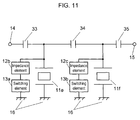
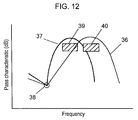
- FIG. 11 is a block diagram of a band switching filter and FIG. 12 shows its pass characteristic.
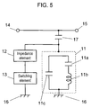
- FIGs. 5-10 are the other examples of resonator circuits used in the first exemplary embodiment of the present invention and show their characteristics.
- a resonator circuit shown in FIG. 1 includes a surface acoustic wave resonator 11, an impedance element 12, a switching element 13, an input terminal 14, an output terminal 15 and a ground 16.
- Input terminal 14 is connected with output terminal 15, one terminal of impedance element 12 and one terminal of surface acoustic wave resonator 11.
- the other terminal of impedance element 12 is connected with one terminal of switching element 13 and the other terminal of switching element 13 is connected with the other terminal of surface acoustic wave resonator 11 and ground 16.
- An equivalent circuit of surface acoustic wave resonator 11 is expressed as a parallel circuit of a capacitance element 11c and a series connection of a capacitance element 11a and inductance element 11b as shown in FIG. 2(a).
- Surface acoustic wave resonator 11 is symbolized as shown in FIG. 2(b) and referred as 11d and is used without any notice, thereafter.
- a parallel resonant frequency of surface acoustic wave resonator 11 can be shifted to an arbitrary resonant frequency.
- a function of a resonant circuit shown in FIG. 1 is explained below.
- FIG. 3 shows a susceptance characteristic of a resonator circuit shown in FIG. 1.
- a susceptance of the resonator circuit when switching element 13 is open is shown by thin curves 18a in FIG. 3.
- Susceptance 18a when Q value of surface acoustic wave resonator 11 is infinity is indicated as intersection 20a of an asymptote 19a and a horizontal line which is zero susceptance.
- the parallel frequency is indicated as intersection 21a of thin susceptance curve 18a and a horizontal line which is zero susceptance and a pass characteristic from the input terminal 14 to the output terminal 15 is shown by curve 24a in FIG.4.
- a series resonant frequency point 20a is shown in FIG. 4 as point 26a.
- the susceptance of the resonator circuit when impedance element 12 is a capacitance element and switching element 13 of the resonator circuit is short is a synthesized susceptance 23a of susceptance 22a of the capacitance element and susceptance 18a of surface acoustic wave resonator 11.
- there is no change in a series resonant frequency because the absolute value of susceptance 18a of surface acoustic wave resonator 11 is infinity at a series resonant frequency of the resonator circuit and the parallel resonant frequency is shown as a intersection 21b of susceptance curve 23a and a horizontal line which is zero susceptance. That is, intersection 21b when switching element 13 is short circuited is lower in frequency than intersection 21a when switching element 13 is open. Therefore, the pass band shifts towards lower without any change of attenuation pole frequency 26a, as shown as frequency characteristic 25a of FIG. 4.
- FIG. 11 is A block diagram of a band switching filter using a resonator circuit shown in FIG. 1 is shown in FIG. 11 and its frequency characteristic is shown in FIG. 12.
- a band switching filter shown in FIG. 11 is a band pass filter and includes surface acoustic wave resonators 11e and 11f, impedance elements 12b and 12c, switching elements 13a and 13b, an capacitance elements 33, 34 and 35, an input terminal 14, an output terminal 15 and a ground 16.
- Input terminal 14 is connected to a terminal of capacitance element 33, the other terminal of capacitance element 33 is connected to a terminal of capacitance element 34, a terminal of surface acoustic wave resonators 11e and a terminal of impedance elements 12b.
- the other terminal of impedance elements 12b is connected to a terminal of switching elements 13a
- the other terminal of capacitance element 34 is connected to a terminal of capacitance element 35
- the other terminal of impedance elements 12c is connected to a terminal of switching elements 13b
- the other terminal of capacitance element 35 is connected to output terminal 15
- the other terminals of surface acoustic wave resonators 11e and 11f and the other terminals of switching elements 13a and 13b are altogether connected to a ground 16.
- the parallel resonant frequency of a resonator circuit shifts by opening or shortening switching elements 13a and 13b.
- a frequency characteristic 36 having pass band 40 is obtained when switching elements 13a and 13b are open and a frequency characteristic 37 having pass band 39 is obtained when switching elements 13a and 13b are short. In both cases, attenuation pole 38 does not change.
- a resonator can be miniaturized but also a filter having frequency characteristics with both pass bands 39 and 40 can be realized with less number of stages by using a band switching filter.
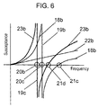
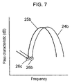
- FIGs. 6 and 7 A susceptance characteristic of a resonator circuit and a pass characteristic looking output terminal 15 from input terminal 14 are shown in FIGs. 6 and 7, respectively.
- the susceptance of the resonator circuit when switching element 13 is open is shown by thin curves 18b, the asymptote in this case is shown as a thin vertical line 19b, the series resonant frequency is shown as a point 20c and the parallel resonant frequency is shown as a point 21c.
- impedance element 12 is a capacitance element
- the susceptance is shown as a thin straight line 22b
- the susceptance of the resonator circuit when switching element 13 is shorted is shown by thick curves 23b
- the asymptote in this case is shown as a thick vertical line 19c
- the series resonant frequency is shown as a point 20b
- the parallel resonant frequency is shown as a point 21d.
- the pass frequency characteristic when the switching element is open is shown as a thin curve 24b
- the attenuation pole is shown as a point 26b.
- the frequency characteristic when the switching element is short circuited is shown as a thick curve 25b
- the attenuation pole is shown as a point 26c.
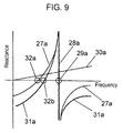
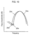
- FIG. 9 A reactance characteristic of the resonator circuit shown in FIG. 8 is shown in FIG. 9 and a pass characteristic looking output terminal 15 from input terminal 14 is shown in FIG. 10.
- FIG. 9 a reactance characteristic of a resonator circuit when switching element 13 is open is shown by thin curves 27a, the asymptote in this case is shown as a thick vertical line 28a, the series resonant frequency is shown as a point 32a and the parallel resonant frequency is shown as a point 29a.
- impedance element 12a is an inductance element
- the reactance is shown as a thin straight line 30a
- the reactance of the resonator circuit when switching element 13 is shorted is shown by thick curves 31a
- the asymptote in this case is shown as a thick vertical line 29a
- the series resonant frequency is shown as a point 32b
- the parallel resonant frequency is shown as a point 29a.
- the frequency characteristic when the switching element is open is shown as a thin curve 24c
- the attenuation pole is shown as a point 26d.
- the frequency characteristic when the switching element is shorted is shown as a thick curve 25c
- the attenuation pole is shown as a point 26e.
- the attenuation pole can be shifted to an arbitrary other frequency.
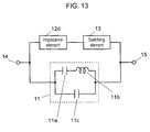
- FIG. 13 is a block diagram of a first example of a resonator circuit used in a band switching filter in accordance with a second exemplary embodiment of the present invention.
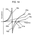
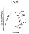
- FIGs. 14 and 15 show its characteristics.
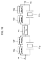
- FIG. 19 is a block diagram of a band switching filter.
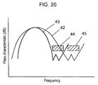
- FIG. 20 shows its pass characteristics.
- FIGs. 16 and 17 are a block diagram of a second example of a resonator circuit used in a band switching filter in accordance with the second exemplary embodiment of the present invention and its characteristic, respectively.
- the resonator circuit 11 used in a band switching filter of the second exemplary embodiment of the present invention shown in FIG. 13 has basically the same construction as that shown in FIG. 1, the blocks having similar functions to those in FIG. 1 are numbered with the same reference number and the detailed explanation is omitted.
- a resonator circuit shown in FIG. 13 is composed of a surface acoustic wave resonator 11, an impedance element 12d, a switching element 13, an input terminal 14 and an output terminal 15.
- Input terminal 14 is connected to a terminal of surface acoustic wave resonator 11 and a terminal of impedance element 12d and the other terminal of impedance element 12d is connected to a terminal of switching element 13 and both the other terminal of switching element 13 and surface acoustic wave resonator 11 are connected to output terminal 15.
- a parallel resonant frequency of surface acoustic wave resonator 11 can be shifted to an arbitrary frequency.
- the function of the resonator circuit when impedance element 12d is a capacitance element is basically just as explained in the first exemplary embodiment.
- the susceptance of the resonator circuit when switching element 13 is open is shown by thin curves 18c, the asymptote in this case is shown as a thin vertical line 19d, the series resonant frequency is shown as a point 20e and the parallel resonant frequency is shown as a point 21e.
- impedance element 12d is a capacitance element
- the susceptance is shown as a thin straight line 22c and the susceptance of the resonator circuit when switching element 13 is shorted is shown by thick curves 23c.
- the asymptote in this case is shown as a thick vertical line 19d
- the series resonant frequency is shown as a point 20e and they do not change from those when switching element 13 is open but the parallel resonant frequency is shown as a point 21f.
- the pass frequency characteristic when the switching element 13 is open is shown as a thin curve 24d and the attenuation pole is shown as a point 26f.
- the pass frequency characteristic when the switching element 13 is shorted is shown as a thick curve 25d and the attenuation pole is shown as a point 26g.
- the attenuation pole can be shifted to an arbitrary frequency.
- the pass frequency characteristic (FIG.15) of the second exemplary embodiment is different from those (FIGs. 4, 7, 10 and 12) of the first exemplary embodiment, that is, the attenuation poles 26f and 26g are higher than the pass bands.
- FIG. 19 A block diagram of a band switching filter using a resonator circuit shown in FIG. 13 is shown in FIG. 19 and its frequency characteristic is shown in FIG. 20.
- the band switching filter shown in FIG. 19 is a band pass filter and comprises surface acoustic wave resonators 11g and 11h, impedance elements 12f and 12g, switching elements 13c and 13d, an input terminal 14, an output terminal 15 and a transmission line 41.
- Input terminal 14 is connected to one terminal of surface acoustic wave resonator 11g and one terminal of switching element 13c, the other terminal of switching element 13c is connected to one terminal of impedance elements 12f, the other terminal of impedance elements 12f is connected to the other terminal of surface acoustic wave resonator 11g and one terminal of transmission line 41.
- the other terminal of transmission line 41 is connected to one terminal of surface acoustic wave resonator 11h and one terminal of switching element 13d, the other terminal of switching element 13d is connected to one terminal of impedance elements 12g, the other terminal of impedance elements 12g is connected to the other terminal of surface acoustic wave resonator 11h and output terminal 15.
- the pass characteristic is as shown in FIG. 20.
- frequency characteristic 42 which attenuation band is 45 is obtained and when switching element 13c and 13d are shorted, frequency characteristic 43 which attenuation band is 44 is obtained. In both cases, the pass band does not change.
- a filter having a frequency characteristic in which both attenuation bands 44 and 45 are attenuated can be realized with less stages and it is hard to receive an effect of ground potential fluctuation.
- One terminal of surface acoustic wave resonator 11 is connected to input terminal 14, the other terminal of surface acoustic wave resonator 11 is connected to both one terminal of impedance element 12e and one terminal of switching element 13, both the other terminal of impedance element 12e and the other terminal of switching element 13 are connected to output terminal 15.
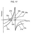
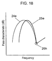
- FIGs. 17 and 18 A reactance characteristic of a resonator circuit and a pass characteristic looking output terminal 15 from input terminal 14 shown in FIG. 16 are shown in FIGs. 17 and 18, respectively.
- the reactance of the resonator circuit when switching element 13 is open is shown as a thin curve 27b
- the asymptote in this case is shown as a thick vertical line 28b
- the series resonant frequency is shown as a point 32c
- the parallel resonant frequency is shown as a point 29b.
- the reactance when impedance element 12e is an inductance element is shown as a thin straight line 30b
- the reactance of the resonator circuit when switching element 13 is shorted is shown as a thick curve 31b
- the asymptote in this case is shown as a thick vertical line 28b
- the series resonant frequency is shown as a point 32d
- the parallel resonant frequency is shown as a point 29b.
- the pass frequency characteristic when the switching element 13 is open is shown as a thin curve 24e and the attenuation pole is shown as a point 26h.
- the pass frequency characteristic when the switching element 13 is shorted is shown as a thick curve 25e and the attenuation pole is shown as a point 26h.
- the pass band can arbitrarily be shifted without shifting the frequency of the attenuation pole.
- band switching filters in accordance with the first or second exemplary embodiment of the present invention By applying band switching filters in accordance with the first or second exemplary embodiment of the present invention to an antenna duplexer, it becomes easily possible to miniaturize the antenna duplexer.
- An antenna duplexer 52 is composed of a transmitter filter 52a and receiver filter 52b, each having different pass band.
- Transmitter filter 52a is electrically connected to an antenna 51 and a transmitter circuit 53 and receiver filter 52b is electrically connected to antenna 51 and a receiver circuit 54.
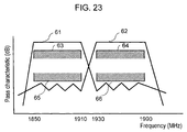
- the transmitter band frequency is 1850MHz to 1910MHz and the receiver band frequency is 1930MHz to 1990MHz.
- a usual antenna duplexer is composed of a transmitter filter 52a having a pass characteristic 61 of pass band 63 and attenuation band 66 and a receiver filter 52b having a pass characteristic of pass band 64 and attenuation band 65 as shown in FIG. 23.
- the transmission band is separated into two bands, 1850MHz to 1885MHz and 1885MHz to 1910MHz and the reception band is separated into also two bands, 1930MHz to 1965MHz and 1965MHz to 1990MHz and a band switching filter of the present invention is used.
- a pass band characteristic in this case is shown in FIG. 24.
- a band switching filter which can switch between a pass characteristic 61a having pass band 63a and attenuation band 66a and a pass characteristic 61b having pass band 63b and attenuation band 66b is used for a transmitter filter and a band switching filter which can switch between a pass characteristic 62a having pass band 64a and attenuation band 65a and a pass characteristic 62b having pass band 64b and attenuation band 65b is used for a receiver filter.
- the pass band is about half and the attenuation band is about two times apart from the pass band and less number of filter stages is enough and a miniaturization of the antenna duplexer can be realized.
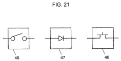
- an element such as a mechanical switch 64, a PIN diode 47 or a FET (field-effect transistor) element 48 shown in FIG. 21 is considered.
- the element it is necessary to arrange the element so that two terminals of the element can be made open or shorted and to select it considering power dissipation of a band switching filter and a current for switching and so on.
- each element can be replaced each other or each element can be replaced by a connection of plural pieces.
- an impedance element can be connected between switching element 13 and ground 16 in the circuit configuration shown in FIG. 8.
- the present invention relates to a band switching filter selectively passing or attenuating only one band of two different bands, which forms a resonator circuit comprising at least a surface acoustic wave resonator, a switching element and an impedance element and shifts at least one of two resonant frequencies of the surface acoustic wave resonator to the other frequency by switching a connection state of the surface acoustic wave resonator and the impedance element by open- or short-circuiting the switching element.
- a resonator circuit comprising at least a surface acoustic wave resonator, a switching element and an impedance element and shifts at least one of two resonant frequencies of the surface acoustic wave resonator to the other frequency by switching a connection state of the surface acoustic wave resonator and the impedance element by open- or short-circuiting the switching element.
- the present invention relates to a band switching filter selectively passing or attenuating only one band of two different bands, which forms a resonator circuit comprising at least a surface acoustic wave resonator, a switching element and an impedance element and in which one terminal of the surface acoustic wave resonator, one terminal of the impedance element and one terminal of the switching element are altogether connected and the other terminal of the impedance element and the other terminal of the switching element are connected.
- the present invention it becomes possible to miniaturize a resonator circuit and to reduce number of filter stages without being effected by a subtle drift of a ground potential by shifting a series resonant frequency of the surface acoustic wave resonator, namely band switching and as a result, miniaturization of a band switching filter can be realized.
Landscapes
- Physics & Mathematics (AREA)
- Acoustics & Sound (AREA)
- Surface Acoustic Wave Elements And Circuit Networks Thereof (AREA)
Applications Claiming Priority (2)
| Application Number | Priority Date | Filing Date | Title |
|---|---|---|---|
| JP6277799 | 1999-03-10 | ||
| JP6277799 | 1999-03-10 |
Publications (2)
| Publication Number | Publication Date |
|---|---|
| EP1035648A2 true EP1035648A2 (fr) | 2000-09-13 |
| EP1035648A3 EP1035648A3 (fr) | 2000-12-27 |
Family
ID=13210149
Family Applications (1)
| Application Number | Title | Priority Date | Filing Date |
|---|---|---|---|
| EP00104611A Withdrawn EP1035648A3 (fr) | 1999-03-10 | 2000-03-03 | Filtre à commutation de bande comportant un résonateur à ondes acoustiques de surface et duplexeur d'antenne comportant un tel filtre |
Country Status (2)
| Country | Link |
|---|---|
| US (1) | US6472953B1 (fr) |
| EP (1) | EP1035648A3 (fr) |
Cited By (9)
| Publication number | Priority date | Publication date | Assignee | Title |
|---|---|---|---|---|
| US6525624B1 (en) * | 1999-08-26 | 2003-02-25 | Hitachi Media Electronics Co., Ltd. | Band-switchable surface acoustic wave antenna duplexer and mobile radio terminal |
| EP1237290A3 (fr) * | 2001-02-27 | 2003-12-10 | Matsushita Electric Industrial Co., Ltd. | Duplexeur d'antenne et dispositif de communication mobile l'utilisant |
| EP1478091B1 (fr) * | 2003-05-13 | 2015-07-08 | TDK Corporation | Dispositif de filtrage avec caractéristique d'attenuation raide en bande passante étroite et filtre de dérivation utlisant celui-ci |
| EP3183816A1 (fr) * | 2014-08-20 | 2017-06-28 | SnapTrack, Inc. | Filtre hf |
| US10320331B1 (en) | 2018-07-30 | 2019-06-11 | International Business Machines Corporation | Applications of a superconducting device that mixes surface acoustic waves and microwave signals |
| US10348245B1 (en) | 2018-07-30 | 2019-07-09 | International Business Machines Corporation | Applications of surface acoustic wave resonators coupled to a josephson ring modulator |
| US10707812B2 (en) | 2018-07-30 | 2020-07-07 | International Business Machines Corporation | Superconducting device that mixes surface acoustic waves and microwave signals |
| US10944362B2 (en) | 2018-07-30 | 2021-03-09 | International Business Machines Corporation | Coupling surface acoustic wave resonators to a Josephson ring modulator |
| EP3183815B1 (fr) * | 2014-08-20 | 2024-04-03 | SnapTrack, Inc. | Duplexeur avec filtres hf accordables |
Families Citing this family (42)
| Publication number | Priority date | Publication date | Assignee | Title |
|---|---|---|---|---|
| DE19960299A1 (de) * | 1999-12-14 | 2001-06-21 | Epcos Ag | Duplexer mit verbesserter Sende-/Empfangsbandtrennung |
| KR20020096008A (ko) * | 2001-06-19 | 2002-12-28 | 엘지전자 주식회사 | 안테나 정합 회로망 |
| EP1341317A1 (fr) | 2001-09-21 | 2003-09-03 | Matsushita Electric Industrial Co., Ltd. | Dispositif haute frequence |
| US6879222B2 (en) * | 2002-02-14 | 2005-04-12 | Cts Corporation | Reduced length metallized ceramic duplexer |
| US6738003B2 (en) * | 2002-07-08 | 2004-05-18 | Cirrus Logic, Inc. | Delta-sigma modulation circuits and methods utilizing multiple noise attenuation bands and data converters using the same |
| JP2004147045A (ja) * | 2002-10-24 | 2004-05-20 | Matsushita Electric Ind Co Ltd | 高周波スイッチ |
| JP3915674B2 (ja) * | 2002-11-20 | 2007-05-16 | 松下電器産業株式会社 | 整合器 |
| DE102004037820A1 (de) * | 2004-08-04 | 2006-03-16 | Epcos Ag | Elektrische Schaltung und Bauelement mit der Schaltung |
| JP4267579B2 (ja) * | 2005-01-31 | 2009-05-27 | パナソニック株式会社 | マルチモード通信装置 |
| JP4634912B2 (ja) * | 2005-11-08 | 2011-02-16 | 株式会社エヌ・ティ・ティ・ドコモ | 可変共振器 |
| FR2927742A1 (fr) * | 2008-02-15 | 2009-08-21 | St Microelectronics Sa | Filtre a resonateur acoustiques de type baw reconfigurable par voie numerique et procede |
| EP2652835A1 (fr) * | 2010-12-16 | 2013-10-23 | Thomson Licensing | Filtre stop bande actif |
| JP6629072B2 (ja) | 2014-02-10 | 2020-01-15 | 株式会社村田製作所 | 可変フィルタ回路および無線通信装置 |
| WO2015119177A1 (fr) | 2014-02-10 | 2015-08-13 | 株式会社村田製作所 | Circuit de filtre variable et dispositif de communication sans fil |
| DE102014111904A1 (de) * | 2014-08-20 | 2016-02-25 | Epcos Ag | Abstimmbares HF-Filter mit Parallelresonatoren |
| JP6390787B2 (ja) | 2015-03-30 | 2018-09-19 | 株式会社村田製作所 | 高周波フィルタ、フロントエンド回路、および通信機器 |
| WO2017069048A1 (fr) * | 2015-10-19 | 2017-04-27 | 株式会社村田製作所 | Filtre à fréquence variable, circuit frontal rf et dispositif de communication |
| US10050603B2 (en) * | 2015-11-04 | 2018-08-14 | Mediatek Inc. | Frequency tunable filter with voltage stressed relaxed switch, and associated apparatus |
| WO2017138539A1 (fr) | 2016-02-08 | 2017-08-17 | 株式会社村田製作所 | Circuit frontal à haute fréquence et dispositif de communication |
| CN108604893B (zh) | 2016-02-08 | 2022-06-17 | 株式会社村田制作所 | 高频滤波电路、双工器、高频前端电路以及通信装置 |
| WO2017170071A1 (fr) | 2016-03-31 | 2017-10-05 | 株式会社村田製作所 | Filtre à fréquence variable, circuit rf frontal et terminal de communication |
| CN109196778B (zh) | 2016-05-27 | 2022-06-14 | 株式会社村田制作所 | 高频滤波电路、高频前端电路以及通信装置 |
| WO2018016279A1 (fr) | 2016-07-22 | 2018-01-25 | 株式会社村田製作所 | Circuit de filtrage haute fréquence, multiplexeur, circuit frontal haute fréquence et dispositif de communication |
| WO2018037967A1 (fr) | 2016-08-23 | 2018-03-01 | 株式会社村田製作所 | Dispositif de filtrage, circuit frontal à haute fréquence, et dispositif de communication |
| WO2018037968A1 (fr) | 2016-08-26 | 2018-03-01 | 株式会社村田製作所 | Dispositif de filtre à onde élastique, multiplexeur, circuit frontal haute fréquence et dispositif de communication |
| WO2018043607A1 (fr) | 2016-09-02 | 2018-03-08 | 株式会社村田製作所 | Dispositif de filtre à ondes acoustiques, circuit frontal à haute fréquence, et dispositif de communication |
| WO2018043606A1 (fr) | 2016-09-02 | 2018-03-08 | 株式会社村田製作所 | Dispositif de filtre à ondes élastiques, circuit frontal à haute fréquence, et appareil de communication |
| WO2018052073A1 (fr) * | 2016-09-16 | 2018-03-22 | 株式会社村田製作所 | Dispositif de filtre d'onde acoustique de surface, multiplexeur, circuit à extrémité avant haute fréquence et dispositif de communication |
| WO2018056224A1 (fr) | 2016-09-21 | 2018-03-29 | 株式会社村田製作所 | Dispositif à ondes élastiques, circuit frontal à haute fréquence et dispositif de communication |
| WO2018061949A1 (fr) * | 2016-09-29 | 2018-04-05 | 株式会社村田製作所 | Dispositif de filtre à ondes acoustiques, multiplexeur, circuit frontal à haute fréquence et dispositif de communication |
| WO2018061950A1 (fr) * | 2016-09-29 | 2018-04-05 | 株式会社村田製作所 | Dispositif de filtre à ondes acoustiques, multiplexeur, circuit frontal haute fréquence et dispositif de communication |
| WO2018097203A1 (fr) | 2016-11-25 | 2018-05-31 | 株式会社村田製作所 | Dispositif de filtre à ondes élastiques, multiplexeur, circuit frontal à haute fréquence, et dispositif de communication |
| CN110199476B (zh) | 2016-12-06 | 2023-01-31 | 株式会社村田制作所 | 滤波器装置、高频前端电路以及通信装置 |
| WO2018135538A1 (fr) | 2017-01-19 | 2018-07-26 | 株式会社村田製作所 | Filtre haute fréquence, circuit frontal haute fréquence et dispositif de communication |
| WO2018139320A1 (fr) | 2017-01-30 | 2018-08-02 | 株式会社村田製作所 | Filtre haute fréquence, circuit frontal haute fréquence et dispositif de communication |
| WO2018159205A1 (fr) | 2017-02-28 | 2018-09-07 | 株式会社村田製作所 | Dispositif formant filtre, multiplexeur, circuit frontal à haute fréquence et appareil de communication |
| CN110383687B (zh) | 2017-03-01 | 2023-02-17 | 株式会社村田制作所 | 高频滤波器、多工器、高频前端电路以及通信装置 |
| WO2018168655A1 (fr) | 2017-03-15 | 2018-09-20 | 株式会社村田製作所 | Multiplexeur, circuit frontal haute fréquence, et dispositif de communication |
| CN110663179B (zh) | 2017-05-18 | 2023-03-21 | 株式会社村田制作所 | 多工器、高频电路以及通信装置 |
| US11563421B2 (en) * | 2018-09-21 | 2023-01-24 | Qorvo Us, Inc. | Acoustic structure having tunable parallel resonance frequency |
| US11757430B2 (en) | 2020-01-07 | 2023-09-12 | Qorvo Us, Inc. | Acoustic filter circuit for noise suppression outside resonance frequency |
| US20230353125A1 (en) * | 2022-04-29 | 2023-11-02 | Avago Technologies International Sales Pte. Limited | Switch-based variable acoustic resonator |
Citations (1)
| Publication number | Priority date | Publication date | Assignee | Title |
|---|---|---|---|---|
| JPH07176912A (ja) * | 1993-12-17 | 1995-07-14 | Sanyo Electric Co Ltd | 高周波フィルタ |
Family Cites Families (13)
| Publication number | Priority date | Publication date | Assignee | Title |
|---|---|---|---|---|
| US4153887A (en) * | 1977-12-05 | 1979-05-08 | The Magnavox Company | Electrically tunable bandpass filter |
| US4462098A (en) * | 1982-02-16 | 1984-07-24 | Motorola, Inc. | Radio frequency signal combining/sorting apparatus |
| US4980660A (en) * | 1986-10-06 | 1990-12-25 | Matsushita Electric Industrial Co., Ltd. | Antenna sharing apparatus for switchable transmit/receive filters |
| US5065121A (en) * | 1988-03-29 | 1991-11-12 | Rf Products, Inc. | Switchable resonator device |
| US5065120A (en) * | 1990-09-21 | 1991-11-12 | Motorola, Inc. | Frequency agile, dielectrically loaded resonator filter |
| EP0732805B1 (fr) * | 1995-03-15 | 2003-01-15 | Matsushita Electric Industrial Co., Ltd. | Filtre à ondes acoustiques de surface |
| US5917387A (en) * | 1996-09-27 | 1999-06-29 | Lucent Technologies Inc. | Filter having tunable center frequency and/or tunable bandwidth |
| JPH10150304A (ja) * | 1996-11-18 | 1998-06-02 | Kyocera Corp | アンテナ共用器用フィルタおよびアンテナ共用器 |
| JPH10247833A (ja) * | 1997-03-06 | 1998-09-14 | Tokin Corp | チューナブルフィルタ |
| DE69834679T2 (de) * | 1997-03-12 | 2006-09-21 | Matsushita Electric Industrial Co., Ltd., Kadoma | Antennenweiche |
| JPH11122139A (ja) * | 1997-10-17 | 1999-04-30 | Murata Mfg Co Ltd | アンテナ共用器 |
| JPH11205066A (ja) * | 1998-01-13 | 1999-07-30 | Murata Mfg Co Ltd | フィルタ |
| JP2000101380A (ja) * | 1998-09-25 | 2000-04-07 | Murata Mfg Co Ltd | 共振回路、フィルタ、送受共用器および通信装置 |
-
2000
- 2000-03-03 EP EP00104611A patent/EP1035648A3/fr not_active Withdrawn
- 2000-03-10 US US09/523,340 patent/US6472953B1/en not_active Expired - Fee Related
Patent Citations (1)
| Publication number | Priority date | Publication date | Assignee | Title |
|---|---|---|---|---|
| JPH07176912A (ja) * | 1993-12-17 | 1995-07-14 | Sanyo Electric Co Ltd | 高周波フィルタ |
Cited By (16)
| Publication number | Priority date | Publication date | Assignee | Title |
|---|---|---|---|---|
| US6525624B1 (en) * | 1999-08-26 | 2003-02-25 | Hitachi Media Electronics Co., Ltd. | Band-switchable surface acoustic wave antenna duplexer and mobile radio terminal |
| EP1237290A3 (fr) * | 2001-02-27 | 2003-12-10 | Matsushita Electric Industrial Co., Ltd. | Duplexeur d'antenne et dispositif de communication mobile l'utilisant |
| EP1508974A3 (fr) * | 2001-02-27 | 2005-09-14 | Matsushita Electric Industrial Co., Ltd. | Duplexeur d'antenne et appareil mobile de communication comprenant ce duplexeur |
| US7038557B2 (en) | 2001-02-27 | 2006-05-02 | Matsushita Electric Industrial Co., Ltd. | Antenna duplexer and mobile communication device using the same |
| EP1478091B1 (fr) * | 2003-05-13 | 2015-07-08 | TDK Corporation | Dispositif de filtrage avec caractéristique d'attenuation raide en bande passante étroite et filtre de dérivation utlisant celui-ci |
| EP3183816A1 (fr) * | 2014-08-20 | 2017-06-28 | SnapTrack, Inc. | Filtre hf |
| EP3183816B1 (fr) * | 2014-08-20 | 2026-04-29 | SnapTrack, Inc. | Filtre hf |
| EP3183815B1 (fr) * | 2014-08-20 | 2024-04-03 | SnapTrack, Inc. | Duplexeur avec filtres hf accordables |
| US10707812B2 (en) | 2018-07-30 | 2020-07-07 | International Business Machines Corporation | Superconducting device that mixes surface acoustic waves and microwave signals |
| US10715083B2 (en) | 2018-07-30 | 2020-07-14 | International Business Machines Corporation | Applications of surface acoustic wave resonators coupled to a Josephson ring modulator |
| US10720887B2 (en) | 2018-07-30 | 2020-07-21 | International Business Machines Corporation | Applications of a superconducting device that mixes surface acoustic waves and microwave signals |
| US10944362B2 (en) | 2018-07-30 | 2021-03-09 | International Business Machines Corporation | Coupling surface acoustic wave resonators to a Josephson ring modulator |
| US11057000B2 (en) | 2018-07-30 | 2021-07-06 | International Business Machines Corporation | Superconducting device that mixes surface acoustic waves and microwave signals |
| US11728772B2 (en) | 2018-07-30 | 2023-08-15 | International Business Machines Corporation | Superconducting device that mixes surface acoustic waves and microwave signals |
| US10348245B1 (en) | 2018-07-30 | 2019-07-09 | International Business Machines Corporation | Applications of surface acoustic wave resonators coupled to a josephson ring modulator |
| US10320331B1 (en) | 2018-07-30 | 2019-06-11 | International Business Machines Corporation | Applications of a superconducting device that mixes surface acoustic waves and microwave signals |
Also Published As
| Publication number | Publication date |
|---|---|
| EP1035648A3 (fr) | 2000-12-27 |
| US6472953B1 (en) | 2002-10-29 |
Similar Documents
| Publication | Publication Date | Title |
|---|---|---|
| EP1035648A2 (fr) | Filtre à commutation de bande comportant un résonateur à ondes acoustiques de surface et duplexeur d'antenne comportant un tel filtre | |
| JP2000323961A (ja) | 弾性表面波共振器を用いた帯域切替フィルタとそれを用いたアンテナ共用器 | |
| US6111482A (en) | Dielectric variable-frequency filter having a variable capacitance connected to a resonator | |
| US7339445B2 (en) | BAW duplexer without phase shifter | |
| US10193527B2 (en) | Branching filter | |
| US7522887B2 (en) | Wireless signal switching circuit and wireless communication apparatus | |
| EP1067686A2 (fr) | Filtre résonateur à ondes acoustiques de surface avec une configuration en T- ponté | |
| CN102801401A (zh) | 通信模块 | |
| KR100387212B1 (ko) | 듀플렉서 및 통신 장치 | |
| JPH01227530A (ja) | 分波器 | |
| US20130210374A1 (en) | Antenna duplexer and communication device using the same | |
| GB2240906A (en) | Radio transceiver filtering arrangement | |
| JP2001069031A (ja) | 無線端末 | |
| KR101850228B1 (ko) | 분파 장치 | |
| JP2021064874A (ja) | 高周波モジュールおよび通信装置 | |
| JP2000349591A (ja) | 弾性表面波フィルタを用いた分波器 | |
| US20020171507A1 (en) | Branching filter package | |
| US11146242B2 (en) | Filter device, multiplexer, radio frequency front end circuit, and communication device | |
| JP3465630B2 (ja) | アンテナ共用器および通信装置 | |
| EP1058334A2 (fr) | Filtre à bande de fréquence variable, duplexeur et appareil de communication | |
| JPH08237165A (ja) | アンテナ共用器 | |
| US11601115B2 (en) | Electronic RF filter | |
| JP2001160766A (ja) | デュプレクサ及び通信機装置 | |
| JPH10247861A (ja) | 周波数帯域切替共用器 | |
| JP3398243B2 (ja) | アンテナ共用器 |
Legal Events
| Date | Code | Title | Description |
|---|---|---|---|
| PUAI | Public reference made under article 153(3) epc to a published international application that has entered the european phase |
Free format text: ORIGINAL CODE: 0009012 |
|
| AK | Designated contracting states |
Kind code of ref document: A2 Designated state(s): DE FR GB |
|
| AX | Request for extension of the european patent |
Free format text: AL;LT;LV;MK;RO;SI |
|
| PUAL | Search report despatched |
Free format text: ORIGINAL CODE: 0009013 |
|
| AK | Designated contracting states |
Kind code of ref document: A3 Designated state(s): AT BE CH CY DE DK ES FI FR GB GR IE IT LI LU MC NL PT SE |
|
| AX | Request for extension of the european patent |
Free format text: AL;LT;LV;MK;RO;SI |
|
| RIC1 | Information provided on ipc code assigned before grant |
Free format text: 7H 03H 9/64 A, 7H 03H 9/72 B |
|
| 17P | Request for examination filed |
Effective date: 20010510 |
|
| AKX | Designation fees paid |
Free format text: DE FR GB |
|
| 17Q | First examination report despatched |
Effective date: 20061110 |
|
| RAP1 | Party data changed (applicant data changed or rights of an application transferred) |
Owner name: PANASONIC CORPORATION |
|
| 18D | Application deemed to be withdrawn |
Effective date: 20110610 |
|
| STAA | Information on the status of an ep patent application or granted ep patent |
Free format text: STATUS: THE APPLICATION IS DEEMED TO BE WITHDRAWN |
|
| R18D | Application deemed to be withdrawn (corrected) |
Effective date: 20110611 |