EP1036441B1 - Procede et appareil permettant la communication sous-marine a debit binaire eleve - Google Patents
Procede et appareil permettant la communication sous-marine a debit binaire eleve Download PDFInfo
- Publication number
- EP1036441B1 EP1036441B1 EP98928506A EP98928506A EP1036441B1 EP 1036441 B1 EP1036441 B1 EP 1036441B1 EP 98928506 A EP98928506 A EP 98928506A EP 98928506 A EP98928506 A EP 98928506A EP 1036441 B1 EP1036441 B1 EP 1036441B1
- Authority
- EP
- European Patent Office
- Prior art keywords
- data
- receiving
- transmitting
- hydrophone
- serial
- Prior art date
- Legal status (The legal status is an assumption and is not a legal conclusion. Google has not performed a legal analysis and makes no representation as to the accuracy of the status listed.)
- Expired - Lifetime
Links
Images


Classifications
-
- H—ELECTRICITY
- H04—ELECTRIC COMMUNICATION TECHNIQUE
- H04B—TRANSMISSION
- H04B11/00—Transmission systems employing ultrasonic, sonic or infrasonic waves
-
- H—ELECTRICITY
- H04—ELECTRIC COMMUNICATION TECHNIQUE
- H04B—TRANSMISSION
- H04B13/00—Transmission systems characterised by the medium used for transmission, not provided for in groups H04B3/00 - H04B11/00
- H04B13/02—Transmission systems in which the medium consists of the earth or a large mass of water thereon, e.g. earth telegraphy
Definitions
- the present invention relates to means for underwater communication. More particularly, the invention relates to a method for carrying out high rate underwater communication, and to an apparatus for carrying out high rate underwater communication according to said method.
- Performing reliable underwater communication is a relatively complicated task. It is known that electromagnetic waves significantly attenuate when propagating through water.
- the only frequency band that is used for electromagnetic underwater communication is the VLF (Very Low Frequency) range, in the range of up to 10 kHz. In this range, high power transmission is needed, and use of extremely long antennas is required at both the receiving and transmitting ends. Therefore, such use is generally limited to submarine communications, and cannot be exploited for personal use.
- VLF Very Low Frequency
- conventional systems use ultrasound acoustic transmission, generally in the frequency range of 20 kHz - 600 kHz. Unfortunately, however, in the acoustic frequency range, the water as a communication medium provides practically only a relatively narrow bandwidth, which limits the speed of the data transfer through water.
- the ability to reliably transfer data through water with acoustic waves is further problematic, due to the different layers of water density, resulting from non-constant speed of sound in water, multipath propagation of the signal, fading, and other environmental disturbances. Furthermore, it is known that the propagation speed of ultrasonic waves in water is significantly lower than the propagation speed of electromagnetic waves in air. Therefore, when it is desired to communicate in water between two apparatuses, of which at least one is not stationary, or moves at a low speed, the Doppler effects significantly adversely affect the signal and the ability to reliably interpret the transmitted data at the receiving apparatus.
- Wireless apparatus for carrying out communication in water is known in the art. Such apparatus is used for example in telemetry systems for transferring data that was accumulated during oceanographic researches, or in communication devices for divers.
- Other existing apparatus which is capable of transferring data at a relatively low rate, generally operates in the range of no more than about 600 bits per second, a rate which is in generally sufficient for telemetry purposes, but not for other purposes which require a significantly higher rate of data transfer, such as real time voice or picture transmission.
- an underwater modem which is capable of transferring data at a much higher transfer rate, at least in the range of about 4800 bits per second to 9600 bits per second.
- Coatelan et Al. "design and test coding OFDM system on the shallow water acoustic channel ", OCEAN 95 MTS/IEEE, Conference Proceedings, Vol. 3, 9-12 October 1995, pages 2065- 2070, discloses an FSK OFDM scheme for carrying out high data rate underwater communication.
- a coherent COFDM modulation system for a time varying frequency selective underwater acoustic channel discloses a coherent OFDM scheme for carrying out high data rate underwater communication.
- existing apparatus enables underwater communication between two locations being at a relatively close range, generally in the range of less than 150 meters, and require a direct "line of sight" between the transmitting and receiving devices.
- Such apparatus does not provide means for carrying out reliable underwater communication between two sites that may be located several kilometers away from one another, and between there is no "line of sight”.
- underwater modem or simply “modem”, when used herein, refers to an apparatus which is capable of transmitting and receiving high-rate data through water, unless otherwise specifically stated.
- high-rate data transmission it is meant to indicate a band rate of at least 1200 bps, and preferably of at least 4800 bps.
- OFDM Orthogonal Frequency Division Multiplexing
- OFDM has been found by the applicants to be the best modulation method for overcoming fading and multipath problems underwater.
- the use of OFDM in itself is not sufficient for solving all the aforesaid problems of underwater communication, and additional means should be provided in order to overcome the Doppler effect, to ensure communications even when a line of sight between the transmitting and receiving apparatuses does not exist, and to assure a reliable (free of errors) communication.
- the Doppler effect is much more severe in underwater acoustic communications than in electromagnetic air communications, as acoustic waves propagate in water at a speed of about 1500m/sec, while electromagnetic waves propagate at the speed of light, i.e., 300,000km/sec in air.
- the modem according to one embodiment of the invention provides means for overcoming the fading and multipath problems, as well as the signal distortions due to the Doppler effects. As will be shown hereinafter, the modem according to the invention can reliably transfer data at a rate much higher than the transfer rate of any prior art underwater communication apparatus.
- the underwater modulator-demodulator (modem) apparatus of the invention for transmitting and receiving data at a high rate through water, is defined by claim 1.
- the receiving section and the transmitting section are contained within the same case, and the transmitting hydrophone and the receiving hydrophone are incorporated within a same hydrophone, and more preferably, the hydrophone is a multidirectional hydrophone.
- the receiving section and the transmitting section may be contained within separate cases.
- the transmitting section further comprises an n -channel differential encoder for receiving data from the serial-to-parallel means, for differentially encoding the data on each one of said n channels, and for providing the differentially encoded data to the n -channel OFDM modulator
- the receiving section further comprises an n -channel differential decoder for receiving n channels of demodulated data from the demodulator, and for differentially decoding said demodulated data.
- the transmitting section further comprises a Forward Error Correcting (FEC) device for encoding the digital data to be transmitted, and for decoding the same by at least one error correcting code, and for outputting the same to the parallel-to-serial device of the receiving section.
- FEC Forward Error Correcting
- the modem uses OFDM modulation so the frequency adjusting device compensates for Doppler effects by changing the frequency of each one of the n pairs of orthogonal sines of the OFDM demodulator by the same measured deviation.
- At least the n -channel OFDM modulator at the transmitting section and the demodulator at the receiving section comprises a DSP, incorporated within an integrated circuit.
- the invention further relates to a method as defined by claim 9.
- the said method performs better when a multidirectional hydrophone is used at the transmitting and at the receiving ends.
- each end may be capable of performing bi-directional communication, and if so, one hydrophone may be used for both receiving and transmitting.
- the duration of each symbol includes a guard time and said guard time is used for symbol synchronization at the receiving end.
- Fig. 1 schematically shows in block diagram form an underwater modem according to a preferred embodiment of the invention.
- the modem 1 comprises both a transmitting section 2 and a receiving section 3. While the existence of said two sections in each modem is necessary in order to carry out a reliable bi-directional communication, there may be cases in which a communication may be carried out according to the invention between two apparatuses, a first one comprising only a transmitting section 2, and a second comprising only a receiving section 3.
- each modem comprises both a transmitting and a receiving section.
- the data source 4 of the transmitting section 2 represents data of any kind, in digital form, that must be transmitted by the wireless modem through water to a receiving modem located underwater in another location.
- the data from the data source (hereinafter also referred to as “the original data") is provided into an FEC (Forward Error Correction) encoder 5, which combines with it additional bits for error correction, in order to provide to the receiving modem the capability of correcting errors which occur due to disturbances in the underwater medium, and for recovering the original data as generated by the data source.
- the FEC encoder 5 is conventional in its structure, applying any type of error correction method known in the art.
- the encoded data data combining the original data and additional bits (hereinafter generally referred to as “the encoded data") is conveyed to an OFDM modulator 6, which modulates the digital data by a plurality of low frequency carriers.
- the modulated signal is then provided to an RF circuit 7, which translates the frequency of the modulated signal to the band of signal ultrasonic frequencies, amplifies it, and transmits it by means of a hydrophone 17 through the underwater medium 100.
- the receiving section 3 receives modulated ultrasonic data from the underwater medium 100 by means of hydrophone 17', which is then provided to an input RF circuit 8, which amplifies it, and translates it down the low frequency range. From the output of the input RF circuit 8, the signal is conveyed to an OFDM demodulator 9, which demodulates the signal, and outputs encoded data. The encoded data from the OFDM demodulator is conveyed into an FEC (Forward Error Correction) decoder 10. The FEC decoder 10 performs a process reversed to the process of the FEC encoder in the transmitting modem. The FEC decoder 10 recovers the original data to be forwarded, as conveyed by the data source 4 to the FEC encoder 5 of the transmitting modem.
- FEC Forward Error Correction
- the FEC decoder 10 contains means for analyzing the encoded data, and if it finds that the data has been corrupted, for example, when passing through the underwater channel, it uses the additional bits added by the FEC encoder 5 to correct errors and recover the original data
- the FEC decoder 10, similar to the FEC encoder 5, is also conventional in its structure, and is capable of recovering errors only to some extent.
- the symbol duration is defined as the sum of the essential duration T plus the guard time ⁇ T .
- the essential duration T of the symbol and the bandwidth B of one modulated carrier of the transmitted signal has to be chosen in order to accomplish frequency nonselective (flat) and slow fading.
- the two requirements for achieving a flat and slow fading are: (1). B ⁇ 1 T d ; and (2). T ⁇ 1 ⁇ f wherein B is the bandwidth of the transmitted signal, T d denotes the delay time of the channel, T is the duration of each transmitted symbol, and ⁇ f denotes the Doppler spread.
- the selected symbol duration T should be in the range of: (4). 2msec ⁇ T ⁇ 100msec
- a maximal bit rate of 3000 bps can be achieved in accordance with DQPSK modulation, and with, for example (31,16,7) forward error correcting BCH code.
- 31 carriers are used, although, of course, different numbers of carriers may be applied.
- the maximal bit rate also increases. For example, a bit rate of 9600 bps may be obtained for about 100 carriers.
- pilots are transmitted along with the information bearing signal, that, as said, comprises said 31 modulated carriers.
- the frequency of the first pilot is selected to be slightly below the lowest frequency modulated carrier, and the second pilot above the highest frequency modulated carrier.
- FIG. 2 A more detailed block diagram of the OFDM modulator 6 of the transmitting section 2 of the modem, according to this particular preferred embodiment of the invention, is shown in Fig. 2.
- the modem according to the invention obviates the need for carrier recovery by using differential modulation.
- the data of each of the plurality of carriers of the OFDM is modulated by a DQPSK (Differential Quadrature Phase Shift Key) modulation.
- DQPSK Different Quadrature Phase Shift Key
- a serial (original) data is inputted into the FEC encoder 5, which combines to it additional bits for enabling error correction at the receiving modem.
- the data in serial form is conveyed to a serial to parallel device 12, essentially a shift register, which divides each section of 62 bits of serial data (hereinafter, each such 62-bit section will also be referred to as a "word") into 31 two-bit symbols of data to be processed in parallel.
- a serial to parallel device 12 essentially a shift register, which divides each section of 62 bits of serial data (hereinafter, each such 62-bit section will also be referred to as a "word") into 31 two-bit symbols of data to be processed in parallel.
- word a shift register
- Bits allocation to symbols and carriers in the modulator carrier number 1 2 ; 30 31 bits b 1 b 2 b 30 b 31 bits b 32 b 33 b 61 b 62 symbols [ b 1 , b 32 ] [ b 2 , b 33 ] [ b 30 , b 61 ] [ b 31 , b 62 ]
- a k (n) are symbols originated in data source 4, encoded by FEC encoder 5, and separated by the serial to parallel device 12, and k denotes the symbol running index.
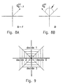
- the structure of each one of the 31 differential encoders is schematically shown in Fig. 4.
- Block 16 indicates a 1-bit adder, and 17 indicates a delay of T seconds, wherein T is the duration of each symbol.
- encoded symbols B k are conveyed in 31 parallel lines 22 to a 31-carrier quadrature OFDM modulator unit 21.
- the structure of the quadrature OFDM modulator is shown in Fig. 5.
- Data splitter 20 maneuvers the data from each line 22 to a corresponding orthogonal modulator 23.
- Each modulator comprises two multipliers 25 and 25', the first multiplier 25 multiplying the data by a cosine sub-carrier, and the second, multiplier 25', multiplying it by an orthogonal, sine sub-carrier.
- Adder 26 adds the result from said two multipliers.
- a similar modulating process is performed in each one of the other 30 modulators.
- the results from all 31 modulators are first combined by summing means 27, then combined by adder 29 with two additional sub-carriers (pilots), cos ⁇ (0) t and cos ⁇ (N+1) t, and finally provided to a hydrophone 28, which transmits the combined signal into the water.
- the purpose of the transmission of said two sub-carriers cos ⁇ (0) t and cos ⁇ (N+1) t is to help to overcome the frequency shift due to Doppler effects in water, as will become apparent as the description proceeds.
- a guard interval is used for synchronization purposes at the receiving modem.
- the duration of the guard interval may vary. However, it should preferably be at least in the order of about 10% of the symbol duration T .
- a band spectrum of a modem is shown in Fig. 13.
- the OFDM transmission is carried out by 31 modulated carriers cos ⁇ (1) t - cos ⁇ (31) t, and two unmodulated carriers (pilots) cos ⁇ (0) t and cos ⁇ (32) t.
- the hydrophone is a multidirectional hydrophone which can transmit or receive essentially equally to or from all directions.
- a multidirectional hydrophone preferably in accordance with OFDM transmission, has been found to significantly improve the reliability of the transmission, and has been found to best overcome various disturbances in the water, such as noise, multipath, and fading.
- such use has been shown to allow an effective, reliable transmission, even when no line of sight exists between the transmitting and the receiving modems. This is indeed surprising since the prior art emphasizes the use of directional hydrophones in underwater communication.
- the RF circuit 8 of the receiving section comprises a preamplifier 40, a local oscillator 42 and mixer 41, a band pass filter 43, and an analog to digital converter 44.
- Data which is received in the hydrophone is first transferred to a preamplifier 40, which amplifies the signal.
- a preamplifier 40 which amplifies the signal.
- an amplified signal is passed on to a mixer 41.
- the signal to the mixer spans a bandwidth of 3.5 kHz according to the example given above, and is positioned, for example, between 40.2 kHz and 43.6 kHz.
- the mixer 41 also receives a frequency of 40 kHz, for example, from the local oscillator, and therefore converts down the bandwidth of the signal to span frequencies of between 200Hz - 3600Hz. Then the signal from the mixer 41 is conveyed to low pass filter 43 and then to an analog to digital (A/D) converter 44, which samples the signal and converts it into a digital representation.
- A/D analog to digital
- the signal as said in digital representation, is then provided into the OFDM demodulator 9.
- the OFDM demodulator 9 comprises a DFT (Discrete Fourier Transformer) 45, a symbol synchronizer 46, a frequency adjust circuit 47, a decision device and differential decoder 48, and a parallel to serial device 49.
- DSP Digital Signal Processing
- the OFDM demodulator 9 is preferably implemented, according to the invention, by one DSP (Digital Signal Processing) circuit, generally available in one integrated chip. However, it may be also implemented by other means well known to those skilled in the art, for example, by a powerful microprocessor.
- the signal from the A/D converter 44 as said, in digital form, is conveyed in parallel to the DFT 45, to the symbol synchronizer 46, and to the frequency adjust circuit 47.
- the symbol synchronizer provides to both the DFT 45 and to the decision device and differential decoder 48 a clock indicating the beginning and the end of a received symbol.
- the frequency adjust circuit 47 inspects the two sub-carriers that are combined with the transmitted signal, for detecting frequency shift, generally due to Doppler effects on the signal propagated in water.
- the frequency adjust circuit 47 continuously updates the decision device and differential decoder 48 of any frequency shift.
- the decision device and differential decoder 48 after detecting 31 symbols simultaneously, provides 62 bits representing the symbols in parallel to the parallel to serial device 49, which separates the symbols into bits, which are then combined into two words, and outputted to the FEC decoder 10.
- Fig. 7 shows the structure of the DFT 45 in greater detail.
- the received signal after being sampled by the A/D, and converted into a digital representation, is conveyed to the DFT on line 50, which is then split into sixty-two parallel lines 51, each one of said parallel lines 51 leading to a corresponding one of sixty-two multipliers 53.
- each one of said sixty-two multipliers is then integrated by a corresponding one of sixty-two integrators 54, each of which, as indicated, performs the integration during a period T of a complete symbol, a period which is indicated to the DFT by a clock provided from the symbol synchronizer 46.
- a vector Q (1 ⁇ N) / k, representing all said 31 vectors, is then conveyed into the decision device and differential decoder 48.
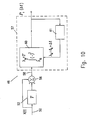
- the decision algorithm of the decision device and differential decoder 48 is illustrated in Figs. 8a, 8b, and 9.
- the DFT output for carrier number n and symbols k-1 and k are vectors Q ( n ) / k -1 and Q ( n ) / k respectively, and ⁇ ( n ) / k denotes the phase difference between Q ( n ) / k and Q ( n ) / k -1, as shown in Figs. 8a and 8b, the values of sin ⁇ ( n ) / k and cos ⁇ ( n ) / k are computed to determine a point on the decision plane diagram of Fig. 9, where the decision regions are indicated.
- the symbol synchronizer 46 performs a symbol synchronization (often also called “timing recovery”), and its purpose is to recover a clock at the symbol rate (or a multiple thereof) from the input to the DFT at line 50, representing in digital form the input modulated signal.
- This clock determines the boundaries of integration of the DFT 45, and is also provided to the decision device and differential decoder 48 for determining the symbol timing boundaries.
- Fig. 10 illustrates the structure of the symbol synchronizer 46
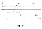
- Fig. 11 is a corresponding timing diagram.
- a received signal x(t) arriving at line 50 is inputted to the synchronizer 46.
- Signal x(t) is in fact S T (t) corrupted by noise and distorted by the channel.
- the synchronizer 46 contains a modulated symbol of duration T+ ⁇ T.
- the synchronizer 46 comprises a summing component 56 having two inputs, one input is provided with x(t) , and a second input is provided with x(t) delayed by the delay block 52 by a period of T (T is the essential part of the symbol).
- the output from the summing component 56 is provided by line 58 to the average power block 57, which measures the average power of the signal provided to it, in purpose to find a timing of minimum power.
- Such search for a minimum-power timing is carried out by varying the beginning of the integration at block 60, and providing the result of the integration into the minimum search block 61.
- the output of said block 61 is fed back to adjust the beginning of the integration at block 60.
- FIG. 11 is a timing diagram illustrating the operation of the symbol synchronizer.
- the signal x(t) comprises a digitally modulated signal of symbols of duration T + ⁇ T
- the beginning of the symbols occur at t k , t k+1 , t k+2 , etc.
- the symbols include the guarding intervals ⁇ T , as shown.
- the synchronizer 46 seeks the case in which P 1 is minimal.
- ⁇ k+1 , ⁇ k+2 , ... indicate the timing of the beginning of processing of the DFT receiving ⁇ t for synchronization
- ⁇ k , ⁇ k+1 , ⁇ k+2 indicate the timing of the end of processing of the DSP.
- the value of ⁇ t converge to such value that guaranties minimum of P 1 .
- Fig. 12 shows that a minimum power occurs during the guard periods ⁇ T .
- P 1 reaches its minimal power value if and only if the system is in full symbol synchronization.
- the symbol synchronizer finds the ( ⁇ t) , for which the power is minimal.
- the OFDM signal when transmitted through the underwater link, may suffer a frequency shift ⁇ F .
- a first and general reason for a frequency shift lies in the frequency accuracy of the transmitter and receiver local oscillators. For example, if the accuracy of the local oscillators is 100ppm each, then for an RF frequency of 50kHz, which is the range of frequency used by the modem for communication, a frequency shift of -5Hz ⁇ ⁇ F ⁇ 5Hz may be expected. Such a frequency shift is generally constant and does not change in time, nor does it depend on the medium of signal propagation.
- the second reason for the carrier shift results from the Doppler effect, particularly due to the movement of either the receiving or the transmitting modem, or both, or due to the change in density of the water. For example, for a relative velocity of 0.5m/sec between the receiving or the transmitting modem, a Doppler frequency shift of about 16Hz is expected.
- two pure carriers are transmitted from the transmitting modem, along with the other n modulated carriers.
- the frequencies of these pilots are tracked at the frequency adjust circuit 47 by two Phase Locked Loop (PLL) devices, each of which is tuned to one pilot frequency.
- PLL Phase Locked Loop
- an indicative frequency shift is provided to each plurality of sin e ⁇ ( n ) and cos ine ⁇ ( n ) components at the DFT.
- Such shift in frequency therefore realigns the bandwidth of the receiving modem for any frequency shift which may occur to the signal due to Doppler effect or due to propagation effects in the water.
- the invention provides a modem which can reliably transfer data at a high rate through water.
- the use of OFDM modulation and a multidirectional hydrophone significantly improve the capability and quality of the data transfer, and provide a significant improvement to the efficient range of transmission
- the modem according to the invention is provided with means for efficiently overcoming severe frequency shifts of the transmitted signal due to Doppler effects.
- the use of OFDM is preferable for transferring data through water according to a preferred embodiment of the invention, as this modulation method enables simultaneous transmission of data over plurality of narrow bandwidth channels, wherein each channel is very little prone to amplitude and phase distortions due to its narrow bandwidth.
- the number of carriers as selected above to be, for example, 31, can vary and is a function of the transfer rate and error correcting consideration. In order to achieve a higher data transfer rate, it is preferable to use a greater number of carriers. Of course, as the number of carriers increases, a more complicated FEC has to be used. According to the invention, it can be assumed that a bit rate of up to about 100kbs is practically achievable.
- a multidirectional hydrophone is preferable, this is not a limitation, as the modem can also function with a directional hydrophone.
- the bandwidth, and the frequencies of the plurality of carriers, are also selective and may depend on design considerations.
- the use of a DSP, as well, is optional, and different alternatives may be used.
Landscapes
- Engineering & Computer Science (AREA)
- Computer Networks & Wireless Communication (AREA)
- Signal Processing (AREA)
- Digital Transmission Methods That Use Modulated Carrier Waves (AREA)
- Arrangements For Transmission Of Measured Signals (AREA)
- Electrical Discharge Machining, Electrochemical Machining, And Combined Machining (AREA)
Claims (15)
- Dispositif de modulation-démodulation sous-marin (modem) pour transmettre et recevoir des données à un débit d'au moins 1200 bits par seconde à travers l'eau, ledit modem comportant :a. une section de transmission (2) comportant :des moyens de source de données (4) comportant des données numériques à transmettre à travers l'eau,des moyens de traitement de données série-parallèle (12), pour diviser des données série en n canaux parallèles,un codeur différentiel à n canaux (15) pour recevoir des données provenant des moyens de traitement de données série-parallèle, pour coder de manière différentielle les données sur chacun desdits n canaux, et pour délivrer les données codées de manière différentielle à un modulateur à multiplexage par répartition orthogonale de la fréquence (OFDM) à n canaux,des moyens de modulation OFDM à n canaux (21), pour recevoir des données provenant desdits n canaux parallèles et pour moduler celles-ci à l'aide de n paires de porteuses à ultrasons, de manière à produire un signal modulé, etdes moyens d'hydrophone (17) pour recevoir ledit signal modulé provenant desdits moyens de modulation à n canaux (21), et pour transmettre celui-ci à travers l'eau,b. une section de réception (3) comportant :des moyens d'hydrophone (17') pour recevoir un signal modulé provenant de l'eau, et pour acheminer celui-ci vers un circuit RF,un circuit RF (8) pour amplifier et mettre en forme le signal modulé reçu, et pour acheminer celui-ci vers des moyens série-parallèle,des moyens série-parallèle (50) pour recevoir les données mises en forme provenant du circuit RF, et pour diviser celles-ci en n canaux parallèles,des moyens de démodulation OFDM à n canaux (9) comportant n paires de sinus à ultrasons orthogonaux pour démoduler le signal mis en forme acheminé vers le démodulateur OFDM à n canaux à partir du circuit RF (8), et pour délivrer en sortie n canaux de données numériques,un décodeur différentiel à n canaux (48) pour recevoir n canaux de données démodulées provenant du démodulateur, et pour décoder de manière différentielle lesdites données démodulées,des moyens parallèle-série (49) pour recevoir n canaux parallèles de données délivrées en sortie provenant du décodeur différentiel à n canaux (48), et pour combiner les données dans des données série, etc. des moyens pour compenser les effets Doppler sur le signal transmis se propageant à travers l'eau, lesdits moyens destinés à compenser les effets Doppler comportant, dans le modulateur (21) de la section de transmission, des moyens pour transmettre au moins une porteuse non-modulée supplémentaire ayant une fréquence connue à la section de réception, et dans la section de réception, un dispositif d'ajustement de fréquence (47) pour mesurer la fréquence de ladite au moins une porteuse non-modulée, pour la comparer à ladite fréquence connue, et pour compenser tout écart entre elles.
- Dispositif de modulation-démodulation sous-marin selon la revendication 1, dans lequel le dispositif d'ajustement de fréquence compense les effets Doppler en changeant la fréquence de chacune desdites n paires de sinus orthogonaux des moyens de démodulation OFDM (9) de la section de réception, par le même écart mesuré par rapport à la fréquence connue de la porteuse non-modulée transmise.
- Dispositif de modulation-démodulation sous-marin selon la revendication 1 ou 2, dans lequel les moyens d'hydrophone de transmission (17) et les moyens d'hydrophone de réception (17') sont incorporés dans un même hydrophone.
- Dispositif de modulation-démodulation sous-marin selon les revendications 1, 2 ou 3, dans lequel les moyens d'hydrophone (17, 17') sont un hydrophone multidirectionnel.
- Dispositif de modulation-démodulation sous-marin selon la revendication 1, dans lequel la section de transmission comporte en outre un dispositif de correction d'erreurs sans voie de retour (FEC) (5) pour recevoir les données numériques à transmettre, pour coder celles-ci par l'intermédiaire d'au moins un code de correction d'erreurs, et pour délivrer en sortie celles-ci au dispositif série-parallèle de la section de transmission.
- Dispositif de modulation-démodulation sous-marin selon l'une quelconque des revendications 1 à 5, dans lequel la section de réception et la section de transmission sont contenues dans le même boítier.
- Dispositif de modulation-démodulation sous-marin selon l'une quelconque des revendications 1 à 5, dans lequel la section de réception et la section de transmission sont contenues dans des boítiers séparés.
- Dispositif de modulation-démodulation sous-marin selon la revendication 1, dans lequel au moins les moyens de modulation OFDM à n canaux (21) dans la section de transmission et les moyens de démodulation OFDM (9) dans la section de réception comportent un traitement numérique des signaux (DSP), incorporé dans un circuit intégré.
- Procédé pour effectuer une communication sous-marine de données à un débit d'au moins 1200 bits par seconde, comportant les étapes suivantes consistant à :le procédé comportant en outre les étapes consistant à :(i) transmettre des données en :a. délivrant des données série sous forme numérique à transmettre,b. fournissant des moyens (12) pour diviser les données série en n canaux parallèles, et affecter des symboles à des groupes de bits de données,c. codant de manière différentielle les symboles (15) dans chacun desdits n canaux parallèles,d. modulant (21) lesdits symboles codés de manière différentielle par l'intermédiaire d'une modulation OFDM à n canaux,e. transmettant lesdites données modulées OFDM par l'intermédiaire d'un hydrophone (17), dans l'eau, et(ii) recevoir lesdites données transmises sous forme compréhensible, en :a. recevant lesdites données modulées OFDM transmises par l'intermédiaire d'un hydrophone (17'),b. démodulant le signal reçue par l'intermédiaire d'un démodulateur OFDM à n canaux (9),c. décodant de manière différentielle (48) les données démodulées dans lesdits n canaux, etd. convertissant (49) les données codées dans lesdits n canaux d'une forme parallèle en une forme série,transmettre simultanément avec les données modulées OFDM au moins une porteuse à ultrasons non-modulée supplémentaire (pilote), etlors de la réception desdites données modulées OFDM et de ladite au moins une porteuse à ultrasons non-modulée supplémentaire par l'hydrophone, mesurer le décalage de fréquence dudit signal non-module par rapport à sa valeur de fréquence attendue, et compenser ledit décalage en ajustant le démodulateur OFDM de la section de réception en conséquence.
- Procédé pour effectuer une communication sous-marine à débit de données élevé selon la revendication 9, dans lequel les sections de réception et de transmission sont contenues dans le même boítier.
- Procédé pour effectuer une communication sous-marine à débit de données élevé selon la revendication 10, dans lequel les hydrophones (17') dans la section de réception et (17) dans la section de transmission sont incorporés dans un même hydrophone.
- Procédé pour effectuer une communication sous-marine à débit élevé selon l'une quelconque des revendications 9 à 11, dans lequel l'hydrophone est un hydrophone multidirectionnel.
- Procédé selon la revendication 9, dans lequel la durée de chaque symbole inclut un temps de garde.
- Procédé selon la revendication 13, dans lequel le temps de garde est utilisé pour une synchronisation de symbole à l'extrémité de réception.
- Procédé selon la revendication 14, dans lequel la synchronisation de symbole est effectuée en détectant un minimum de la puissance moyenne du signal de différence dans une période de temps égale audit temps de garde, le signal de différence étant défini en tant que différence entre le signal reçu et le signal reçu retardé d'une durée d'un symbole.
Applications Claiming Priority (3)
| Application Number | Priority Date | Filing Date | Title |
|---|---|---|---|
| IL12237597A IL122375A (en) | 1997-12-01 | 1997-12-01 | Method and apparatus for carrying out high data rate underwater communication |
| IL12237597 | 1997-12-01 | ||
| PCT/IL1998/000288 WO1999029058A1 (fr) | 1997-12-01 | 1998-06-18 | Procede et appareil permettant la communication sous-marine a debit binaire eleve |
Publications (2)
| Publication Number | Publication Date |
|---|---|
| EP1036441A1 EP1036441A1 (fr) | 2000-09-20 |
| EP1036441B1 true EP1036441B1 (fr) | 2004-02-11 |
Family
ID=11070910
Family Applications (1)
| Application Number | Title | Priority Date | Filing Date |
|---|---|---|---|
| EP98928506A Expired - Lifetime EP1036441B1 (fr) | 1997-12-01 | 1998-06-18 | Procede et appareil permettant la communication sous-marine a debit binaire eleve |
Country Status (7)
| Country | Link |
|---|---|
| EP (1) | EP1036441B1 (fr) |
| AT (1) | ATE259560T1 (fr) |
| AU (1) | AU8032198A (fr) |
| DE (1) | DE69821647T2 (fr) |
| IL (1) | IL122375A (fr) |
| WO (1) | WO1999029058A1 (fr) |
| ZA (1) | ZA9810874B (fr) |
Families Citing this family (15)
| Publication number | Priority date | Publication date | Assignee | Title |
|---|---|---|---|---|
| PT1105986E (pt) * | 1998-08-21 | 2005-10-31 | Evologics Gmbh | Metodo para a transmissao de informacao bem como um sistema adequado para o efeito |
| DE19904747A1 (de) * | 1998-08-21 | 2000-02-24 | Rudolf Bannasch | Verfahren zur Übertragung von Informationen sowie ein geeignetes System hierfür |
| US7573807B1 (en) | 1999-09-17 | 2009-08-11 | Alcatel-Lucent Usa Inc. | Method and apparatus for performing differential modulation over frequency in an orthogonal frequency division multiplexing (OFDM) communication system |
| EP1178328A1 (fr) * | 2000-07-31 | 2002-02-06 | Xios S.A. | Dispositif acoustique de navigation pour la plongée sousmarine |
| US7966497B2 (en) | 2002-02-15 | 2011-06-21 | Qualcomm Incorporated | System and method for acoustic two factor authentication |
| US20030212549A1 (en) * | 2002-05-10 | 2003-11-13 | Jack Steentra | Wireless communication using sound |
| US7401224B2 (en) | 2002-05-15 | 2008-07-15 | Qualcomm Incorporated | System and method for managing sonic token verifiers |
| EP1385283A1 (fr) * | 2002-07-22 | 2004-01-28 | Culture Com. Technology (Macau) Ltd. | Procédé de communication au travers d'un moyen |
| NL2000820C2 (nl) * | 2007-08-17 | 2009-02-18 | Tetradon B V | Werkwijze voor het behandelen van vloeistoffen met elektromagnetische golven. |
| GB0802807D0 (en) * | 2008-02-15 | 2008-03-26 | Rhodes Mark | Through water multimode communications system |
| US9264151B1 (en) | 2009-07-29 | 2016-02-16 | Shopkick, Inc. | Method and system for presence detection |
| US10304069B2 (en) | 2009-07-29 | 2019-05-28 | Shopkick, Inc. | Method and system for presentment and redemption of personalized discounts |
| CN102611662A (zh) * | 2012-02-14 | 2012-07-25 | 河海大学常州校区 | 一种低成本低功耗的水声调制解调器 |
| DE102014001171B3 (de) * | 2014-01-31 | 2015-01-22 | Bundesrepublik Deutschland, vertreten durch das Bundesministerium der Verteidigung, vertreten durch das Bundesamt für Ausrüstung, Informationstechnik und Nutzung der Bundeswehr | Verfahren zur Bildübertragung unter Wasser |
| CN111163021B (zh) * | 2020-01-06 | 2022-05-27 | 厦门狄耐克智能科技股份有限公司 | 一种基于二线的数据转换传输设备 |
Family Cites Families (2)
| Publication number | Priority date | Publication date | Assignee | Title |
|---|---|---|---|---|
| JP2883238B2 (ja) * | 1992-02-06 | 1999-04-19 | 日本放送協会 | 符号化変調装置および復調装置 |
| JPH0946314A (ja) * | 1995-07-28 | 1997-02-14 | Toshiba Corp | Ofdm変調装置 |
-
1997
- 1997-12-01 IL IL12237597A patent/IL122375A/en not_active IP Right Cessation
-
1998
- 1998-06-18 AU AU80321/98A patent/AU8032198A/en not_active Abandoned
- 1998-06-18 DE DE69821647T patent/DE69821647T2/de not_active Expired - Lifetime
- 1998-06-18 EP EP98928506A patent/EP1036441B1/fr not_active Expired - Lifetime
- 1998-06-18 AT AT98928506T patent/ATE259560T1/de not_active IP Right Cessation
- 1998-06-18 WO PCT/IL1998/000288 patent/WO1999029058A1/fr not_active Ceased
- 1998-11-27 ZA ZA9810874A patent/ZA9810874B/xx unknown
Also Published As
| Publication number | Publication date |
|---|---|
| ZA9810874B (en) | 1999-06-01 |
| EP1036441A1 (fr) | 2000-09-20 |
| DE69821647T2 (de) | 2004-12-23 |
| WO1999029058A1 (fr) | 1999-06-10 |
| IL122375A (en) | 2001-05-20 |
| AU8032198A (en) | 1999-06-16 |
| IL122375A0 (en) | 1999-01-26 |
| ATE259560T1 (de) | 2004-02-15 |
| DE69821647D1 (de) | 2004-03-18 |
Similar Documents
| Publication | Publication Date | Title |
|---|---|---|
| US6130859A (en) | Method and apparatus for carrying out high data rate and voice underwater communication | |
| EP1036441B1 (fr) | Procede et appareil permettant la communication sous-marine a debit binaire eleve | |
| US11063674B2 (en) | Communications system | |
| CN1980213B (zh) | 接收方法、接收装置 | |
| KR960003835B1 (ko) | 신호 가중 시스템 | |
| US5974094A (en) | FFT receiver for MFSK | |
| US20030156534A1 (en) | Communication system using OFDM | |
| AU2001282726A1 (en) | Communication system using OFDM | |
| EP1891762B1 (fr) | Systeme de communications sous-marines | |
| US4881245A (en) | Improved signalling method and apparatus | |
| US7310286B1 (en) | System for undersea digital acoustic communications | |
| US20040218521A1 (en) | Method for data communication between a single-carrier system and a multi-carrier system | |
| Rohling et al. | Comparison of PSK and DPSK Modulation in a Coded OFDM System | |
| TW391089B (en) | Method and apparatus for carrying out high data rate underwater communication | |
| Chary et al. | Device-to-device data transmission over sound waves using FSK/BPSK/QPSK | |
| Valčić et al. | A model of OFDM based maritime VHF communication system for data exchange | |
| Law et al. | Communication with an underwater ROV using ultrasonic transmission | |
| US20020067772A1 (en) | Method and system for sending information over metal wire | |
| Chary et al. | FSK/BPSK/QPSK | |
| Haines et al. | Simultaneous oblique sounding with Doppler analysis and low‐probability‐of‐intercept communications using digital ionosondes | |
| EP0172048A2 (fr) | Procédé de transmission de données numériques par modulation d'un signal haute fréquence | |
| CN119402326A (zh) | 一种适用于elf通信的调制解调通信方法及系统 | |
| Hatwar et al. | A Survey on DSP Implementation of OFDM UW Acoustics Modem | |
| Rey | An HF Multitone Modem | |
| Shaarani | DESIGN OF A COMPUTER NETWORK USING A SINE WAVE, LINE-OF-SIGHT, FREQUENCY MODULATION SYSTEM IN THE 30MHZ TO 50 MHZ RANGE. |
Legal Events
| Date | Code | Title | Description |
|---|---|---|---|
| PUAI | Public reference made under article 153(3) epc to a published international application that has entered the european phase |
Free format text: ORIGINAL CODE: 0009012 |
|
| 17P | Request for examination filed |
Effective date: 20000529 |
|
| AK | Designated contracting states |
Kind code of ref document: A1 Designated state(s): AT BE CH CY DE DK ES FI FR GB GR IE IT LI LU MC NL PT SE |
|
| 17Q | First examination report despatched |
Effective date: 20010613 |
|
| RAP1 | Party data changed (applicant data changed or rights of an application transferred) |
Owner name: UNDERWATER TECHNOLOGIES CENTER LTD. |
|
| GRAH | Despatch of communication of intention to grant a patent |
Free format text: ORIGINAL CODE: EPIDOS IGRA |
|
| GRAS | Grant fee paid |
Free format text: ORIGINAL CODE: EPIDOSNIGR3 |
|
| GRAA | (expected) grant |
Free format text: ORIGINAL CODE: 0009210 |
|
| AK | Designated contracting states |
Kind code of ref document: B1 Designated state(s): AT BE CH CY DE DK ES FI FR GB GR IE IT LI LU MC NL PT SE |
|
| PG25 | Lapsed in a contracting state [announced via postgrant information from national office to epo] |
Ref country code: NL Free format text: LAPSE BECAUSE OF FAILURE TO SUBMIT A TRANSLATION OF THE DESCRIPTION OR TO PAY THE FEE WITHIN THE PRESCRIBED TIME-LIMIT Effective date: 20040211 Ref country code: LI Free format text: LAPSE BECAUSE OF FAILURE TO SUBMIT A TRANSLATION OF THE DESCRIPTION OR TO PAY THE FEE WITHIN THE PRESCRIBED TIME-LIMIT Effective date: 20040211 Ref country code: FR Free format text: LAPSE BECAUSE OF FAILURE TO SUBMIT A TRANSLATION OF THE DESCRIPTION OR TO PAY THE FEE WITHIN THE PRESCRIBED TIME-LIMIT Effective date: 20040211 Ref country code: CY Free format text: LAPSE BECAUSE OF FAILURE TO SUBMIT A TRANSLATION OF THE DESCRIPTION OR TO PAY THE FEE WITHIN THE PRESCRIBED TIME-LIMIT Effective date: 20040211 Ref country code: CH Free format text: LAPSE BECAUSE OF FAILURE TO SUBMIT A TRANSLATION OF THE DESCRIPTION OR TO PAY THE FEE WITHIN THE PRESCRIBED TIME-LIMIT Effective date: 20040211 Ref country code: BE Free format text: LAPSE BECAUSE OF FAILURE TO SUBMIT A TRANSLATION OF THE DESCRIPTION OR TO PAY THE FEE WITHIN THE PRESCRIBED TIME-LIMIT Effective date: 20040211 Ref country code: AT Free format text: LAPSE BECAUSE OF FAILURE TO SUBMIT A TRANSLATION OF THE DESCRIPTION OR TO PAY THE FEE WITHIN THE PRESCRIBED TIME-LIMIT Effective date: 20040211 |
|
| REG | Reference to a national code |
Ref country code: GB Ref legal event code: FG4D |
|
| REG | Reference to a national code |
Ref country code: CH Ref legal event code: EP |
|
| REG | Reference to a national code |
Ref country code: IE Ref legal event code: FG4D |
|
| REF | Corresponds to: |
Ref document number: 69821647 Country of ref document: DE Date of ref document: 20040318 Kind code of ref document: P |
|
| PG25 | Lapsed in a contracting state [announced via postgrant information from national office to epo] |
Ref country code: SE Free format text: LAPSE BECAUSE OF FAILURE TO SUBMIT A TRANSLATION OF THE DESCRIPTION OR TO PAY THE FEE WITHIN THE PRESCRIBED TIME-LIMIT Effective date: 20040511 Ref country code: GR Free format text: LAPSE BECAUSE OF FAILURE TO SUBMIT A TRANSLATION OF THE DESCRIPTION OR TO PAY THE FEE WITHIN THE PRESCRIBED TIME-LIMIT Effective date: 20040511 Ref country code: DK Free format text: LAPSE BECAUSE OF FAILURE TO SUBMIT A TRANSLATION OF THE DESCRIPTION OR TO PAY THE FEE WITHIN THE PRESCRIBED TIME-LIMIT Effective date: 20040511 |
|
| PG25 | Lapsed in a contracting state [announced via postgrant information from national office to epo] |
Ref country code: ES Free format text: LAPSE BECAUSE OF FAILURE TO SUBMIT A TRANSLATION OF THE DESCRIPTION OR TO PAY THE FEE WITHIN THE PRESCRIBED TIME-LIMIT Effective date: 20040522 |
|
| PG25 | Lapsed in a contracting state [announced via postgrant information from national office to epo] |
Ref country code: LU Free format text: LAPSE BECAUSE OF NON-PAYMENT OF DUE FEES Effective date: 20040618 Ref country code: IE Free format text: LAPSE BECAUSE OF NON-PAYMENT OF DUE FEES Effective date: 20040618 |
|
| PG25 | Lapsed in a contracting state [announced via postgrant information from national office to epo] |
Ref country code: MC Free format text: LAPSE BECAUSE OF NON-PAYMENT OF DUE FEES Effective date: 20040630 |
|
| NLV1 | Nl: lapsed or annulled due to failure to fulfill the requirements of art. 29p and 29m of the patents act | ||
| REG | Reference to a national code |
Ref country code: CH Ref legal event code: PL |
|
| PLBE | No opposition filed within time limit |
Free format text: ORIGINAL CODE: 0009261 |
|
| STAA | Information on the status of an ep patent application or granted ep patent |
Free format text: STATUS: NO OPPOSITION FILED WITHIN TIME LIMIT |
|
| EN | Fr: translation not filed | ||
| 26N | No opposition filed |
Effective date: 20041112 |
|
| REG | Reference to a national code |
Ref country code: IE Ref legal event code: MM4A |
|
| PG25 | Lapsed in a contracting state [announced via postgrant information from national office to epo] |
Ref country code: PT Free format text: LAPSE BECAUSE OF NON-PAYMENT OF DUE FEES Effective date: 20040711 |
|
| PGFP | Annual fee paid to national office [announced via postgrant information from national office to epo] |
Ref country code: DE Payment date: 20120613 Year of fee payment: 15 |
|
| PGFP | Annual fee paid to national office [announced via postgrant information from national office to epo] |
Ref country code: GB Payment date: 20120613 Year of fee payment: 15 Ref country code: FI Payment date: 20120626 Year of fee payment: 15 |
|
| PGFP | Annual fee paid to national office [announced via postgrant information from national office to epo] |
Ref country code: IT Payment date: 20120626 Year of fee payment: 15 |
|
| GBPC | Gb: european patent ceased through non-payment of renewal fee |
Effective date: 20130618 |
|
| PG25 | Lapsed in a contracting state [announced via postgrant information from national office to epo] |
Ref country code: FI Free format text: LAPSE BECAUSE OF NON-PAYMENT OF DUE FEES Effective date: 20130618 |
|
| REG | Reference to a national code |
Ref country code: DE Ref legal event code: R119 Ref document number: 69821647 Country of ref document: DE Effective date: 20140101 |
|
| PG25 | Lapsed in a contracting state [announced via postgrant information from national office to epo] |
Ref country code: GB Free format text: LAPSE BECAUSE OF NON-PAYMENT OF DUE FEES Effective date: 20130618 Ref country code: DE Free format text: LAPSE BECAUSE OF NON-PAYMENT OF DUE FEES Effective date: 20140101 |
|
| PG25 | Lapsed in a contracting state [announced via postgrant information from national office to epo] |
Ref country code: IT Free format text: LAPSE BECAUSE OF NON-PAYMENT OF DUE FEES Effective date: 20130618 |