EP1036538A2 - Dispositif pour essorer un balai à laver - Google Patents
Dispositif pour essorer un balai à laver Download PDFInfo
- Publication number
- EP1036538A2 EP1036538A2 EP00302128A EP00302128A EP1036538A2 EP 1036538 A2 EP1036538 A2 EP 1036538A2 EP 00302128 A EP00302128 A EP 00302128A EP 00302128 A EP00302128 A EP 00302128A EP 1036538 A2 EP1036538 A2 EP 1036538A2
- Authority
- EP
- European Patent Office
- Prior art keywords
- wringing
- movement
- crank arm
- operating
- linkage
- Prior art date
- Legal status (The legal status is an assumption and is not a legal conclusion. Google has not performed a legal analysis and makes no representation as to the accuracy of the status listed.)
- Withdrawn
Links
- 230000007246 mechanism Effects 0.000 claims abstract description 69
- 238000006073 displacement reaction Methods 0.000 claims description 17
- 238000013459 approach Methods 0.000 claims description 5
- 230000000694 effects Effects 0.000 claims description 4
- 230000001419 dependent effect Effects 0.000 claims 1
- 150000001875 compounds Chemical class 0.000 description 5
- 239000002250 absorbent Substances 0.000 description 1
- 230000000295 complement effect Effects 0.000 description 1
- 230000003247 decreasing effect Effects 0.000 description 1
- 230000000881 depressing effect Effects 0.000 description 1
- 239000000463 material Substances 0.000 description 1
- 230000004048 modification Effects 0.000 description 1
- 238000012986 modification Methods 0.000 description 1
Images


Classifications
-
- A—HUMAN NECESSITIES
- A47—FURNITURE; DOMESTIC ARTICLES OR APPLIANCES; COFFEE MILLS; SPICE MILLS; SUCTION CLEANERS IN GENERAL
- A47L—DOMESTIC WASHING OR CLEANING; SUCTION CLEANERS IN GENERAL
- A47L13/00—Implements for cleaning floors, carpets, furniture, walls, or wall coverings
- A47L13/10—Scrubbing; Scouring; Cleaning; Polishing
- A47L13/50—Auxiliary implements
- A47L13/58—Wringers for scouring pads, mops, or the like, combined with buckets
- A47L13/59—Wringers for scouring pads, mops, or the like, combined with buckets with movable squeezing members
Definitions
- This invention relates to mop wringing devices. It is particularly concerned, but not necessarily exclusively so, with devices for wringing mops of the kind which comprise a pad, which may be provided with tufts of water-absorbent material, mounted on a generally planar frame
- Devices for wringing such mops that comprise a pair of plates between which the mop head is placed and excess moisture wrung from it as the plates are brought together to apply pressure to the mop head.
- the device is to be manually or pedal operated, only a limited force can be applied by the operator.
- a mop-wringing device having a rotary member connected to a wringing member of the device and an operating mechanism for pivoting the rotary member comprising a force input element and means in said mechanism to increase the rate of movement of said input element relative to that of the rotary member as the wringing member approaches a closed operative position.
- the rotary member operates the mop wringing member through a further mechanism which also increases the rate of movement of the rotary member relative to the rate at which it displaces the wringing member as the operative position is approached and pressure is increasingly applied to the mop head by the wringing member.
- a further mechanism is that referred to above, in EP 0160532, in which the toggle linkage increases the force applied to the mop wringing member.
- the two mechanisms can thus complement each other giving a final mechanical advantage that is the product of the mechanical advantage of each, so producing a considerably greater wringing force for the same amount of operator effort.
- a mop wringing device having a rotary member connected to a mop wringing member to move said wringing member between an open position in an inoperative state of the device and a closed position in an operative state of the device, an operating mechanism for rotation of said member between said positions comprising a first linkage that is displaceable in a first stage of moving the wringing member from said open position, said mechanism then being operable to move the wringing member through a second stage of movement to said closed position while the elements of said first linkage remain fixed relative to each other, in each of said stages of movement the operating mechanism effecting the movement of the wringing member with a positive mechanical advantage.
- said first linkage comprises a first toggle joint and the movement through the second stage can be effected by articulating a second toggle joint.
- a considerable mechanical advantage can be produced by bringing the operative toggle joint close to an in-line position.
- the elements of the toggle joint can be held fixed in the second stage of the wringing member movement by locking them in an over-centre position.
- the operating mechanism has respective hand and/or pedal operating members for the two stages of movement.
- the mechanism may have a single hand or pedal operating member that is displaceable to effect both the first and second stages of movement.
- a mop wringing device comprising a rotary member connected to a mop wringing member to move said member between an open position in which the wringing device is inoperative and a closed operative position of the device, an actuating mechanism for the rotary member comprising a first operating member movable to give a first stage of said movement from the open position, a toggle joint being displaceable to a substantially in-line but over-centre position in said first stage, and a second operating member movable to give a second stage of said movement bringing the wringing member to said closed position being arranged to act with a greater mechanical advantage than the first operating member in said first stage and while said toggle joint is maintained in said over-centre position.
- the second operating member can be arranged to act on a further toggle joint to bring said joint towards an in-line position as the closed position of the device is reached.
- a mop wringing device comprising a rotary member connected to a mop wringing member for displacing said wringing member and an actuating mechanism for said rotary member having a toggle joint connected to a hand or pedal operating member movable to displace the toggle joint to a substantially in-line but over-centre position in a first stage of the movement of the wringing member from an open position, the operating member then being arranged to act with a greater mechanical advantage on the wringing member while said toggle joint remains in said over-centre position in a second stage of the movement of said operating member to the closed position.
- a crank arm projects from the rotary member and the or an operating member of the mechanism is pivotally attached to the crank arm by a first pivot at a position radially outwardly from the rotary member, the operating member also being pivotally attached to a control linkage by a second pivot at a position spaced from the first pivot, the members connected by said second pivot comprising a toggle joint, said control linkage being attached by a third pivot to a fixed location spaced from the first and second pivots and comprising a toggle joint between said second and third pivots, the arrangement being such that when the operating member is pivoted on the crank arm to displace the wringing mechanism from its open position, the toggle joint is brought to the substantially in-line but over-centre position while the crank arm is being pivoted to turn the rotary member.
- a second toggle joint can be provided between the first toggle joint and the third, fixed pivot.
- the movement of the second operating member completes the closing movement of the wringing mechanism while bringing the second toggle joint towards an in-line position, the first toggle joint meanwhile remaining substantially in-line because of the stability conferred by its over-centre position.
- the first stage of movement is performed by bringing the second toggle joint to a substantially in-line but over-centre position and then bringing the first toggle joint, between the second joint and the first operating member, towards an in-line position.
- the movement is performed, it is preferably arranged that the first stage of the movement produces a larger angle of displacement of the rotary member as little if any pressure will be applied to an inserted mop head in the initial movement from the open position of the wringing mechanism, whereby the movement required for the second stage will be less and a greater mechanical advantage can therefore be achieved.
- the mechanism can be arranged that with the first toggle joint held in its stable in-line position, the control linkage and the crank arm act together as a second toggle joint in which the first, second and third pivots can be brought towards an in-line position, so producing an angular displacement of the crank arm substantially smaller than the angular displacement of the operating member.
- Means can be provided for inter-engaging the crank arm and lever when moving away from said in-line position and releasing the lever from constraint by the control linkage so that said movement can be performed with the crank arm and lever pivoting together.
- the matching angular movements of the lever and crank arm then reduce the distance the lever must be moved to open the wringer.
- the wringing mechanism can be opened by returning each member to its starting position.
- the member performing the final closing movement it may be preferred to provide a return spring which will return the member as soon as it is released.
- the linkage between said second and third pivots can be arranged to be collapsible or foldable on the return movement of the member so that the changing distance between the second and third pivots as the linkage collapses accommodates the joint pivoting of the operating member with the crank arm.
- biasing means act on said linkage to resist said folding, while means movable with the operating member are engageable with the linkage as the operating member moves away from said in-line position to collapse the linkage against the force of the biasing means.
- the loading applied by the biasing means is not allowed to increase significantly other than during that part of the operating member movement in which no wringing pressure is applied. While wringing pressure is being applied, an increase of the biasing force can increase undesirably the effort the operator must exert.
- the biasing means can comprise a spring which, conveniently, is attached at one end close to the crank arm pivot, so that end has only a small displacement over the entire range of movement of the mechanism, while the other end is attached to a part of the mechanism movable about the third pivot to be displaceable further from the rotary shaft as the mechanism collapses. With this arrangement it is possible to ensure that the spring undergoes little deformation when wringing pressure is being applied.
- a wringer mechanism comprising a crank arm for displacing a mop wringing member and rotatable about an axis by an operating member of the mechanism to exert a wringing action on an inserted mop head, said member being pivoted to the crank arm and to a control linkage pivoted to a fixed point remote from the member and crank arm, to apply wringing pressure the operating member being movable through a range of movement comprising a first region in which it pivots together with the crank arm and displaces the control linkage from a non-operative state and, after bringing the control mechanism to its operative state, the member moves through a second region in which it pivots on the control linkage relative to the crank, said wringing action being exerted over a least a part of said second region of the movement in which the operating member angular displacement is controlled by said linkage to be substantially greater than angular displacement the operating member imparts to the crank arm, whereby to reduce
- the operating member In the first region of its range of movement, when typically no wringing force is being applied, the operating member merely acting to displace the wringing member to and from a fully open position in which the mop head is inserted into or removed from the wringing device.
- the non-operative control linkage may be arranged to allow the lever and crank arm to move together as a unit.
- a wringer mechanism for a mop wringing device comprising a crank arm for displacing a mop wringing member of the device and being rotatable about an axis by each of a pair of operating members of the mechanism in sequence to exert a wringing pressure on a mop head inserted in the device, a first of the members being pivoted to the crank arm and to a control linkage pivoted at a fixed pivot remote from the member and crank arm, a second of the members being connected to the control linkage to pivot it about said fixed pivot, one of said two members being displaceable to pivot the crank arm from a non-operative state towards an operative state, the other of said members being displaceable to complete the pivoting of the crank arm to the operative state, said wringing action being exerted over at least a part of the displacement of said other member in which said displacement is controlled by said linkage to be substantially greater than the displacement imparted to the crank arm, whereby
- Figs. 1 to 5 of the drawings illustrate a mop wringing device of the form described in EP 0160532 but which has been modified to incorporate an operating device in accordance with the present invention.
- a main frame is formed by a pair of side plates 2 connected together rigidly by a flanged transverse angle plate 4 and by a trough-like perforated support plate 6 on the generally flat bottom of which a mop head (not shown) can be placed.
- a pressure plate 14 is mounted in the main frame, above and generally co-extensive with the support plate 6.
- the pressure plate 14 is displaceable between a raised position in which it extends almost vertically from adjacent the rear edge of the support plate 6 to give free access for a mop head to be placed on the support plate 6, and a lowered position in which it is brought close to and substantially parallel to the planar base of the support plate in order to apply wringing pressure to the mop head placed on the plate 6.
- the pressure plate 14 For movement between the open and closed positions, the pressure plate 14 is articulated to the main frame through pivot pins 24 at its flanged rear edge engaging elongated slots 26 in the side plates 2.
- a torque tube 34 rotatably mounted in the side plates 2 has C-shaped lever arms 36 secured to it to extend around the rear and over the top of the support plate 6 to be connected to the pressure plate 14 by respective pivot links 38. The pressure plate thus moves in the manner described in EP 0160532 when the torque tube is rotated.
- operating hand lever 40 is not secured to the torque tube, but is pivoted to a parallel pair of crank arms 42 fixed to the torque tube 34.
- the lever 40 is connected to the crank arms 42 by a first pivot shaft 44 spaced a short distance from its lower end.
- a second pivot shaft 46 on the lever nearer its lower end is pivoted to a parallel pair of compound levers of a control linkage.
- Each compound lever has two main components, namely a bell crank lever 48 and an extension arm 50.
- the bell crank lever 48 can swing on a third pivot shaft 52 mounted in the side plates 2 and engaging the bell crank lever at the angle of its arms. From that pivot a longer leg 48a of the bell crank lever is pivoted at 54 to the extension arm 50.
- the other end of the arm 50 is connected to the hand lever by the pivot shaft 46.
- the bell crank lever 48, arm 50 and pivot 52 form a toggle joint which is movable between an over-centre but substantially in-line position as shown in Figs. 2 and 3, and a folded or collapsed state in which the extension arm 50 pivots clockwise relative to the bell crank lever 48, as shown in Fig. 4 and 5.
- the shorter arm 48b of each bell crank lever is connected by a tension spring 56 to the crank arm 42, at a point 58 near to, but spaced from the torque tube 34.
- Figs. 2 to 5 illustrate a sequence of movements of the operating mechanism from the final mop-wringing position in Fig. 2 to the fully open position of the pressure plate 14 in Fig. 5.
- the operation will first be described for the final wringing movement from the position in Fig. 3, where pressure is about to be applied to an inserted mop head, to the final mop-wringing position in Fig. 2.
- the anti-clockwise rotation of the torque tube brings the pivot links 38 to positions substantially radial to the torque tube whereby the lever arms 36 and links 38 act as toggle mechanism, also increasing the force applied to the inserted mop, as described in more detail in EP 0160532.
- the wringing force is increased relative to the force on the operating lever in proportion to the product of the mechanical advantage of the mechanism 40,42,48,50 and the mechanical advantage of the mechanism 36,38,42.
- the wringing force may thereby approach 100 times the force applied to the lever, so that a very considerable wringing force can be produced by a person of only modest strength.
- the operative position shown in Fig. 2 is the final end position, flange 62 on the crank arm preventing further movement of the lever.
- the movement is stopped short of the in-line position of the pivots 44,46,52 so that the wringing pressure force acts to assist the return of the pressure plate.
- the handle is swung clockwise to raise the pressure plate, and when the position in Fig. 3 is reached an abutment pin 64 on the lever comes to bear on the extension arm 50.
- Continuing movement now deflects the arm 50 to collapse the compound lever 48,50, as shown in Fig. 4, by folding it about the pivot 54.
- Fig. 4 also shows how, immediately afterwards, the lever comes against the flange 62 projecting from the crank arm 42 so that the lever arm and crank arm are locked together in the following clockwise movement.
- the compound lever continues to be folded against the spring force as the second pivot 46 moves with the lever.
- the spring 56 is extended, but only to a small degree. The operator experiences little resistance therefore from the extension of the spring, although a relatively high rate spring is employed to ensure the compound lever is securely locked in its extended position when the wringing force is to be applied.
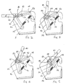
- Figs. 6 to 9 show another mop wringing device according to the invention. Like the first embodiment it incorporates the wringing device of EP 0160532 as already illustrated in Fig. 1. Some of the features of this earlier device are also shown in Fig. 6 and are indicated by the same reference numbers but for simplicity they have been omitted from the further figures. As before, reference can be made to EP 0160532 for a further description of the earlier mechanism.
- crank arms 68 fixed to the torque tube 34 have a hand lever 70 connected to their upper ends by a pivot shaft 72.
- the lever 70 has a short extension 74 beyond the pivot shaft 72 to a further pivot shaft 76 connecting it to a link 78 attached at its other end by a pivot 80 to a lug 82.
- the lug 82 is secured to a rotary shaft 84 offset from the pivot 80 and mounted in fixed bearings in the side plates 2. Also secured to the shaft 84 is a second lever 86.
- the first lever 70 In a first stage of the closing movement of the device, the first lever 70 is swung anti-clockwise.
- the crank arms 68, the lever extension 74 and the link 78 pivot relative to each other during this stage, the shaft 84, and thus the pivot connection 80, remaining stationary.
- the pivots 72,76,80 of the extension 74 and link 78 form a toggle joint that is brought by this movement slightly past the in-line state to an over-centre position, as shown in Fig. 8, before a stop 92 on the extension 74 prevents further movement.
- the pressure plate 14 may be nearly closed and it may already apply some slight pressure to a mop inserted in the wringer device, but because the toggle joint is over-centred it is stable. Any wringing force will prevent the pressure plate springing up and the lever 70 can be released.
- FIG. 10 shows a wringer device similar in most respects to that shown in Figs. 6-9, in the same state as that in Figs. 6 and 7, but with the second lever replaced by a pedal mechanism.
- foot pedal 102 connected to a pivot 104 on a carrier frame 106, shown only fragmentarily, on which the wringer device is mounted, is linked by a tie rod 108 to a short lever 110 fixed to the shaft 84. Wringing pressure is applied by depressing the pedal 102 against the force of a light spring 112 which normally holds the shaft 84 in the rest position shown in Fig 10.
Landscapes
- Cleaning Implements For Floors, Carpets, Furniture, Walls, And The Like (AREA)
- Disintegrating Or Milling (AREA)
- Drying Of Solid Materials (AREA)
Applications Claiming Priority (2)
| Application Number | Priority Date | Filing Date | Title |
|---|---|---|---|
| GBGB9906023.8A GB9906023D0 (en) | 1999-03-16 | 1999-03-16 | Mop wringing devices |
| GB9906023 | 1999-03-16 |
Publications (2)
| Publication Number | Publication Date |
|---|---|
| EP1036538A2 true EP1036538A2 (fr) | 2000-09-20 |
| EP1036538A3 EP1036538A3 (fr) | 2002-10-23 |
Family
ID=10849712
Family Applications (1)
| Application Number | Title | Priority Date | Filing Date |
|---|---|---|---|
| EP00302128A Withdrawn EP1036538A3 (fr) | 1999-03-16 | 2000-03-15 | Dispositif pour essorer un balai à laver |
Country Status (2)
| Country | Link |
|---|---|
| EP (1) | EP1036538A3 (fr) |
| GB (1) | GB9906023D0 (fr) |
Cited By (1)
| Publication number | Priority date | Publication date | Assignee | Title |
|---|---|---|---|---|
| WO2015085016A1 (fr) | 2013-12-03 | 2015-06-11 | Micronova Manufacturing, Inc. | Essoreuse pour balais, comprenant balais plats et balais à franges |
Family Cites Families (5)
| Publication number | Priority date | Publication date | Assignee | Title |
|---|---|---|---|---|
| GB8410892D0 (en) * | 1984-04-27 | 1984-06-06 | Jani Jack Ltd | Mop-wringing devices |
| US5070574A (en) * | 1990-04-10 | 1991-12-10 | Rubbermaid Commercial Products Inc. | Mop wringer |
| DE29505111U1 (de) * | 1995-03-25 | 1995-05-24 | Nadler, Walter, 87471 Durach | Presse für Reinigungsgeräte |
| GB2314501B (en) * | 1996-06-28 | 2000-03-08 | John Crisp | Squeezers for mops and the like |
| LU88802A1 (fr) * | 1996-08-12 | 1997-02-13 | Az Int Sa | Essoreuse pour des bandes a franges ou serpilleres comprenant un panneau presseur a mouvement de translation parallele depourvue de fond pour permettre aux bandes a franges ou serpillieres de la traverser pour pouvoir etre plongee dans le liquide contenu dans un seau sous-adjacent |
-
1999
- 1999-03-16 GB GBGB9906023.8A patent/GB9906023D0/en not_active Ceased
-
2000
- 2000-03-15 EP EP00302128A patent/EP1036538A3/fr not_active Withdrawn
Cited By (3)
| Publication number | Priority date | Publication date | Assignee | Title |
|---|---|---|---|---|
| WO2015085016A1 (fr) | 2013-12-03 | 2015-06-11 | Micronova Manufacturing, Inc. | Essoreuse pour balais, comprenant balais plats et balais à franges |
| EP3076847A4 (fr) * | 2013-12-03 | 2017-08-16 | Micronova Manufacturing, Inc. | Essoreuse pour balais, comprenant balais plats et balais à franges |
| US10575704B2 (en) | 2013-12-03 | 2020-03-03 | Micronova Manufacturing, Inc. | Wringer for mops, including flat mops and string mops |
Also Published As
| Publication number | Publication date |
|---|---|
| EP1036538A3 (fr) | 2002-10-23 |
| GB9906023D0 (en) | 1999-05-12 |
Similar Documents
| Publication | Publication Date | Title |
|---|---|---|
| US10144442B2 (en) | Travel stroller folding and latch mechanism | |
| JP5659243B2 (ja) | アニマルタグ・アプリケータ | |
| US6515245B2 (en) | Closing assistance mechanism for an electrical switchgear apparatus and drive mechanism of an electrical switchgear apparatus equipped with such an assistance mechanism | |
| JPH06203685A (ja) | 三位置スイッチ駆動機構 | |
| ITVR20010022A1 (it) | Telaio ripiegabile ad ombrello particolarmente per passeggini | |
| HK1043349A1 (zh) | 嬰兒車 | |
| US3061843A (en) | Articulated bed | |
| JPH04249820A (ja) | 三位式スイッチの作動機構 | |
| ITBO960484A1 (it) | Dispositivo di apertura e chiusura di porte o simili, in special modo negli apparecchi elettrodomestici o simili | |
| WO2007045396A1 (fr) | Dispositif de préhension, en particulier pour des poussettes, landaus, etc. | |
| JP2007297044A (ja) | 車両ルーフの移動可能なルーフ部分 | |
| EP1036538A2 (fr) | Dispositif pour essorer un balai à laver | |
| US4553343A (en) | Automatic ironing press | |
| CA1067555A (fr) | Table pliable a dispositif de verrouillage ameliore retenant les elements sur un meme plan horizontal et prevenant les accidents de manipulation | |
| JPH0271719A (ja) | モッピングユニット | |
| CN105539692B (zh) | 一种便携式交通工具的锁定与解锁机构 | |
| US20250042461A1 (en) | Auxiliary mechanism for assisting folding or unfolding frame of pushcart and pushcart | |
| JPS59222187A (ja) | ミシンの布地挾み | |
| JP2004530151A (ja) | テンプルを自動的に開く機構のついた眼鏡 | |
| CN103909506A (zh) | 工具机的支撑架 | |
| US4723457A (en) | Sudden interlocking and teleunlocking mechanical assembly for a translation switch having automatic reinforced interlocker | |
| SU1669391A3 (ru) | Захватное устройство | |
| US1626624A (en) | Ironing board | |
| US1798058A (en) | Switch lock with toggle-lever driving mechanism for the switch rod | |
| DE102004034054B3 (de) | Mantelbeschickbare Trommelwaschmaschine mit einem Laugenbehälterdeckel |
Legal Events
| Date | Code | Title | Description |
|---|---|---|---|
| PUAI | Public reference made under article 153(3) epc to a published international application that has entered the european phase |
Free format text: ORIGINAL CODE: 0009012 |
|
| AK | Designated contracting states |
Kind code of ref document: A2 Designated state(s): AT BE CH CY DE DK ES FI FR GB GR IE IT LI LU MC NL PT SE |
|
| AX | Request for extension of the european patent |
Free format text: AL;LT;LV;MK;RO;SI |
|
| PUAL | Search report despatched |
Free format text: ORIGINAL CODE: 0009013 |
|
| AK | Designated contracting states |
Kind code of ref document: A3 Designated state(s): AT BE CH CY DE DK ES FI FR GB GR IE IT LI LU MC NL PT SE |
|
| AX | Request for extension of the european patent |
Free format text: AL;LT;LV;MK;RO;SI |
|
| STAA | Information on the status of an ep patent application or granted ep patent |
Free format text: STATUS: THE APPLICATION IS DEEMED TO BE WITHDRAWN |
|
| 18D | Application deemed to be withdrawn |
Effective date: 20021001 |